La Crosse Technology WS-8010U User manual
- Category
- Weather stations
- Type
- User manual

WS-8010U
Wireless 433 MHz
Giant Radio Controlled Weather Center
Instruction Manual

2
TABLE OF CONTENTS
Topic Page
Inventory of Contents/ Additional Equipment 3
Quick Set-up 3
Detailed Set-Up Guide
Battery Installation 3-4
Program Mode
Function Keys/Buttons 5
LCD Contrast Setting 6
Time Zone Setting 6
Daylight Saving Time Setting 6
Language Setting 6-7
12/24 hour Time Setting 7
Selecting °F or °C
7
World Time Setting 7
World/Local Time Display Setting 8
Graphic Time Display Options/Settings 8-9
Time and Date Settings 9
Features
About WWVB 10
Weather Forecast Icons/ Tendency Arrows 10-11
Additional Sensors (Set-Up & Selection) 11-12
Date/Rainfall Display 12-13
Rain Gauge Set-Up 13
Minimum & Maximum Records (Indoor, outdoor, & resetting) 13-14
Mounting 15-16
Troubleshooting 17
Maintenance & Care 17
Specifications 18
Warranty Information 19

3
INVENTORY OF CONTENTS
1. WS-8010U—Giant Radio Controlled Weather Center.
2. TX4U—Remote Thermo-Hygro (temperature-humidity) includes: mounting
bracket/receptor, rain cover, and two mounting screws.
3. Instruction manual and warranty card.
ADDITIONAL EQUIPMENT (not included)
1. Three fresh 1.5V C batteries.
2. Two fresh 1.5V AA batteries.
3. Philips screwdriver.
4. Three mounting screws.
QUICK SET-UP
1. Insert two AA batteries into the Remote Thermo-Hygro.
2. Insert three C batteries into the Weather Center.
3. Wait 5 minutes for the Weather Center to receive remote signals from the
Remote Thermo-Hygro sensor.
4. Wait an additional 10 minutes for the WWVB signals to be received. If the
WWVB signal is not found in this time period, manually set the time (see
complete instructions) or wait until the Weather Center conducts its nightly
auto-search during the ideal reception time (12:00 am to 6:00 am).
5. Mount the units, ensuring that all units are sending and receiving signals.
DETAILED SET-UP GUIDE
I. BATTERY INSTALLATION
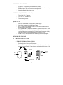
A. REMOTE THERMO-HYGRO SENSOR
1. Pull the cylindrical rain cover off the sensor.
2. Remove the battery cover (located on the backside of the sensor, above the
mounting post and bracket). Press the arrow and push in the direction of the
Battery
Cover
Mounting
Bracket/Receptor
Rain
Cover
Thermo-Hygro
Sensor

4
arrow, sliding the battery cover off.
3. Observing the correct polarity install 2 AA batteries. The batteries will fit
tightly (avoid start-up problems—make sure they do not spring free).
4. Replace the battery cover, and place the rain cover snugly onto the sensor.
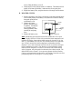
B. WEATHER CENTER
1. Remove the battery cover. Place a solid object in the space provided at the
lower-central position of the battery cover (above the + and SET buttons),
then push up and pull out
on the battery cover.
2. Observe the correct
polarity, and install three
C batteries. The batteries
will fit tightly (avoid
start-up problems, make
sure they do not spring
free).
3. Replace the battery cover.
Note:
Immediately after the batteries have been installed the LCD (Liquid
Crystal Display) will flash. Within a few seconds the indoor temperature and
humidity will display, along with the default settings for the time (12:00), the
date (1.1), the weekday (FR), the year (99), and the forecast icon (clouds with
sun). Within 5 minutes the outdoor temperature and humidity should be
displayed. If not, remove batteries from both units for 10 seconds, and repeat
battery installation procedure. If the batteries are installed during optimal
times for WWVB reception (12:00 am to 6:00 am) the time will be received
within 10 minutes, after the signals from the sensors have been received. The
default WWVB time is Eastern. Do not press any buttons while the Weather
Center is receiving signals from the sensor—the Weather Center does not allow
programming when it is searching for or receiving signals.
Battery
Cover
Battery Compartment
Weather
Center

5
PROGRAM MODE
The Program Mode is laid out in a manner that allows you to program each function
separately, or you can follow the instructions entirely to program the Weather Center
completely. Complete programming is usually done for the initial set-up, and will
require you to skip step 1 of each programming section (from section III to XI). The
programming mode can be exited at any time by pressing key #1, #2, or #3, or by waiting
for the 20-second time-out to take effect.
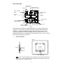
I. FUNCTION KEYS
Note:
Figure 1 shows the left side view. Buttons #1, #2, and #3 are located to the
left of the LCD screen. Figure 2 shows the backside of the Weather Center, and
the location of the + and SET buttons.
Key #1
Key #2
Key #3
SET
button
+
button
Figure 1.
Figure 2.
Indoor temperature
display
Tendency
arrow
Forecast
icons
Indoor humidity
display
Outdoor humidity
display
Outdoor
temperature display
Date/Rain display
Satellite icon (indicates
outdoor transmission)
WWVB Tower Icon
(indicates time reception)
Hour
Triangle
Minute dots
Time display
Indicates world
time is shown

6
II. SETTING THE LCD CONTRAST
1. Press the SET button, the default setting “LCD 5” will flash in the DATE
DISPLAY.
2. There are 8 LCD contrast levels to choose from—“LCD 0” is the lightest
and “LCD 7” is the darkest.
3. Press the + button to toggle through the various settings.
4. Press the SET button to confirm, and to advance to the Time Zone setting
mode.
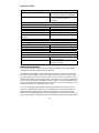
III. TIME ZONE SETTING
1. Press the SET button two times to enter the Time Zone setting mode.
2. The default setting “ET –5” will be flashing in the DATE DISPLAY.
3. Press the + button to select the appropriate time zone (see chart for time
zones and their corresponding codes). The time will change simultaneously
with time zone selection.
Atlantic AT -4
Eastern ET -5
Central CT -6
Mountain MT -7
Pacific PT -8
Alaska AL -9
4. Press the SET button to confirm, and to advance to the Daylight Saving
Time (DST) setting mode.
IV. DAYLIGHT SAVING TIME (DST)
1. Press the SET button three times to enter the DST setting mode.
2. Press the + button to select either “DT On” or “DT OFF.”
3. Press the SET button to confirm, and to advance to the Language setting
mode.
V. LANGUAGE SETTING
Note:
The language setting only affects the language that the weekday is
displayed in.
1. Press the SET button four times to enter the Language setting mode.
2. The default setting “USA” (representing English) will flash in the DATE
DISPLAY.
3. Press the + to select a language (see chart for languages and corresponding
abbreviations).

7
English USA
French F
Italian I
Dutch NL
Danish DK
Spanish E
Japanese J
German D
4. Press the SET button to confirm, and to advance to the 12/24 hour setting
mode.
VI. 12/24 HOUR SELECTION
1. Press the SET button five times to enter the 12/24 hour selection mode.
2. The default setting of “12h” will flash in the TIME DISPLAY.
3. Press the + button to select either “12h” (AM/PM mode) or “24h” (military
time) time display.
4. Press the SET button to confirm, and to advance to the °F or °C selection.
VII. SELECTING °F OR °C
1. Press the SET button six times to enter the °F or °C selection mode.
2. Press the + button to change from the flashing default setting “°F” to “°C.”
3. The temperature displays change simultaneously as °F or °C are selected.
4. Press the SET button to confirm, and to advance to the World Time setting.
VIII. WORLD TIME SETTING
Note:
The World Time allows you to set a second time, enabling you to keep track
of the time in another part of the world. When setting the World Time, it is only
possible to set the hour—the minutes will correspond to the current local time.
“WORLD” will appear above the time in the TIME DISPLAY when this mode is
being set.
1. Press the SET button seven times to enter the World Time setting mode.
2. Press the + button to select the hour.
3. Press the SET button to confirm the World Time, and to advance to the
World/Local Time Display Setting.
Note:
The mention of “local time” refers to your current local time, and is
meant to distinguish between world time and your time. Unless WWVB signals
have been received, it is important to remember while setting the World/Local
Time display that you have not yet set the local time and will not appear as the
correct time.

8
IX. WORLD/LOCAL TIME DISPLAY
Note: The World and Local Time can be displayed in three different ways. The
Local Time can be the constant time shown, the World Time can be the constant
time shown, or the World/Local Time can be displayed so that they show
intermittently. The intermittent display option will show the times alternately in
one-second increments until that option is confirmed then, they will show for five-
second increments. When the World Time is being displayed, “WORLD” will
appear in the TIME DISPLAY above the time.
1. Press the SET button eight times to reach the World/Local Time Display
setting mode.
2. The constant local time is the default setting and is shown in the TIME
DISPLAY.
3. Press the + button to select the next display option—constant world time.
Press the + button again to select the next display option—intermittent
world/local time display.
4. Press the SET button to confirm, and to advance to the Graphic Time
Display Options setting mode.
X. GRAPHIC TIME DISPLAY OPTIONS
Note:
There are four Graphic Time Display Options. All options have a
triangular arrow that points to the hour printed on the perimeter of the LCD
screen, which corresponds to the local-time hour. The four options affect how the
minutes are displayed. The hour-arrow and the minute-dots encompass the
outermost perimeter of the LCD screen. When this mode is being set, a “clock-
face” icon will be shown in the DATE DISPLAY. The Graphic Time Display
Options are as follows:
Option 1
: The hour-arrow points and flashes to an hour that corresponds with the
current local time. The minute-dots will line the perimeter of the LCD screen.
The minutes that have past will remain (not flashing) on the screen, but the current
minute will flash in a minute position that corresponds to the minute of the local
time.
Option 2
: The hour-arrow points and flashes to an hour that corresponds with the
current local time. The minute-dot will flash in a minute position that corresponds
to the minute of the local time.
Option 3
: Appears on the screen to be the same as Option 2, except the hour-
arrow and the minute-dot do not flash.
Option 4
: The hour-arrow points and flashes to an hour that corresponds with the
current local time. The minute-dots will start at zero, and count up by fives until
the minute-dots reach the current minute of the local time. Once the current
minute has been met, the minute-dots disappear and again begin to count up by
fives, continually repeating the process.

9
1. Press the SET button nine times to enter the Graphic Time Display Options
setting mode.
2. The default setting “1” will flash in the DATE DISPLAY.
3. To shift to other Graphic Time Display Options, press the + button. The
flashing option number in the DATE DISPLAY will shift from 1 through to
4 (depending on how many times the + button is pressed).
4. Press the SET button to confirm the setting, and to advance to the Local
Time setting mode.
XI. TIME AND DATE SETTINGS
Note:
Any time and dates that have been programmed manually will be
overridden once reception from the WWVB has been established. A flashing
WWVB Tower icon (displayed between the hour and minute of the time) indicates
that the Weather Center is receiving the WWVB radio signals. A non-flashing
tower icon indicates the time and date signal has been received.
1. Press the SET button 10 times to enter the Local Time setting mode.
2. The “12:00” default setting will flash in the TIME DISPLAY.
3. To change the hour press the + button.
4. Press the SET button to confirm the hours, and to advance to set the
minutes.
5. Press the + button to change the minutes; holding the + button down will
change the minutes, 5 minutes at a time.
6. Press the SET button to confirm the minutes, and to advance to set the year.
7. The “99” default year will flash in the DATE DISPLAY.
8. Press the + button to advance the year.
9. Press the SET button to confirm the year, and to enter the month setting
mode. The default “1” will flash.
10. Press the + button to change the month.
11. Press the SET button to confirm the month, and to enter the date setting
mode. The default “1” will flash.
12. Press the + button to advance the date.
13. Press the SET button to confirm the date, and to enter the weekday setting
mode. The default “FR” will flash.
14. Press the + button to change the weekday.
15. Press the SET button to confirm the weekday and to exit the programming
mode.

10
FEATURES
I. ABOUT WWVB (Radio Controlled Time)
The NIST (National Institute of Standards and Technology—Time and
Frequency Division) WWVB radio station is located in FT. Collins, Colorado,
and transmits the exact time signal continuously throughout the United States at
60 kHz. The signal can be received from up to 2,000 miles away through the
internal antenna in the Weather Center. However, due to the nature of the Earth’s
Ionosphere, reception is very limited during daylight hours. The Weather Center
will search for a signal every night, when reception is best. The WWVB radio
station derives its signal from the NIST Atomic clock in Boulder, Colorado. A
team of atomic physicists continually measure every second, or every day, to an
accuracy of ten billionths of a second a day, creating an international standard,
measuring a second as 9,192,631,770 vibrations of a Cesium-133 atom in a
vacuum. This Weather Center regulates the WWVB sensor.
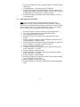
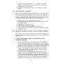
II. WEATHER FORECAST
The weather forecasting feature is estimated to be 75% accurate, basing the
weather forecast solely upon the change of air-pressure over time. The
WS-8010U averages past air-pressure readings to provide an accurate forecast—
creating a necessity to disregard all weather forecasting for 12-24 hours after the
Weather Center has been set-up, reset, or moved from one altitude to another (i.e.
from one floor of a building to another floor).
A. WEATHER ICONS
There are 3 possible weather icons that will be displayed in the FORECAST
DISPLAY:
Sunny—indicates that the weather is expected to improve (not that the weather
will be sunny).
Sun with Clouds—indicates that the weather is expected to be fair (not that the
weather will be sunny with clouds).
Clouds with Rain—indicates that the weather is expected to get worse (not that
the weather will be rainy).
The weather icons change when the unit detects a change in air pressure. The
icons change in order, from “sunny” to “sun with clouds” to “clouds with rain,”
or the reverse. It will not change from “sunny” directly to “clouds with rain,”

11
although it is possible for the change to occur quickly. If the symbols do not
change then the weather has not changed, or the change has been slow and
gradual.
B. WEATHER TENDENCY ARROWS
There are 2 weather tendency arrows, one appearing on each side of the Weather
Icons. One tendency arrow points up (on the left side of the Display) and one
points down (on the right side of the Display). These arrows reflect current
changes in the air pressure. An arrow pointing up indicates that the air pressure
is increasing and the weather is expected to improve or remain fair, an arrow
pointing down indicates that the air pressure is decreasing and the weather is
expected to become worse or remain poor. No arrow means the pressure is
stable.
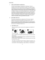
III. ADDING MORE SENSORS (optional)
The WS-8010U can receive signals from up to three Sensors. The Sensor
model(s) that you choose will come with their own set of instructions—follow
those instructions for a complete guide to setting up. Following are some brief
instructions for the basic set-up of additional sensors with the WS-8010U.
Additional sensors can be purchased through the same dealer as this Weather
Center, or by contacting La Crosse Technology directly (contact information can
be found at the end of this manual). A TX4U will monitor temperature and
humidity (it is the same model that comes with the WS-8010U), a TX3U will
monitor temperature only, and the TX3UP monitors temperature via a 10 foot
probe for use in pools, spas, etc. The TX3 units do not monitor humidity, thus
when they transmit their information to the Weather Center dashes “- -” appear in
the Humidity Display.
Note:
When setting up multiple sensors it is important to remove the batteries
from all existing units in operation, then to insert batteries first into all the
sensors, and in numeric sequence. Second install batteries into the Weather
Center. Transmission problems will arise if this is not done correctly and if the
total time for set-up exceeds 6 minutes.
SET-UP OF MULTIPLE SENSORS
Note:
The first sensor signal that the Weather Center receives is automatically
assigned as the “boxed #1.” The 2
nd
to be received is the “boxed #2,” and the 3
rd
is the “boxed #3.”
1. It is necessary to remove the batteries from all units currently in operation.
2. Remove the battery covers to all sensor units (new and old).
3. Place all sensors in a numeric sequential order.

12
4. In sequential order, install batteries into the sensors (follow the same battery
installation procedures seen in section I. A).
5. Install batteries into the Weather Center.
6. Follow the Programming Mode instructions to program and set-up the
Weather Center.
B. SELECTING WHICH SENSOR DATA TO DISPLAY
1. To view the outdoor temperature and humidity from a different sensor,
press key #1. A shift from a “boxed #1” to a “boxed #2” should be
observed under the DATE DISPLAY (between the Outdoor Temperature
and Outdoor Humidity Displays).
2. Press key #1 a second time to shift from the “boxed #2” to the “boxed #3”.
(Information will display only if you have three sensors in operation).
3. To view information from the first sensor again, press key #1.
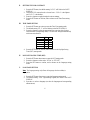
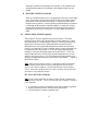
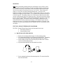
IV. DATE DISPLAY
Note:
The DATE DISPLAY defaults to the month/date/year format. This display
area can show an alternate way of displaying the date.
1. Press key #2. This changes the DATE DISPLAY
from the standard month/date/year to a display
showing the weekday/month/date.
2. Press key #2 to change back to the original date
display.
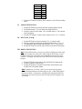
V. RAINFALL DISPLAY (optional)
Note:
If the Rainfall feature is opted, its information
will display in the Date Display, in two possible configurations. To change what
and how the information is displayed, use key #2.
Following step 1 above:
1. Press key #2 again to change from the DATE DISPLAY to the RAIN
DISPLAY. “TOTAL RAIN - -.- in” is now displayed with corresponding
measurements.
Note:
The display of “OFL” indicates that the TX4U Rainfall Gauge has
reached 99.9 inches, and has overflowed. To reset, hold down key #2 for 3
seconds.
Key #1
Key #2
Key #3

13
2. Press key #2 again, and “RAIN 24h - -.- in” is displayed. This is the
measure of the total number of inches of rainfall over a 24-hour period,
updated daily at 7:00 am local time.
3. To return to the standard DATE DISPLAY of month/date/year, press
key #2.
VI. RAIN GAUGE SET-UP (optional)
The WS-8010U has the optional feature of adding the TX5U Rain Gauge, which
can be purchased through the same dealer as the WS-8010U or by contacting
La Crosse Technology directly. The rain gauge will measure rain as Total Rain in
inches, or as 24-hour Rainfall in inches. The Rain Gauge comes with its own set
of complete instructions, here we will briefly explain how to set-up.
1. Remove batteries from all existing units in operation.
2. Install batteries into all temperature sensors (as per instructions in section
III. A under Features).
3. Install batteries into the Rain Gauge.
4. Install batteries into the Weather Center.
5. Wait for proper reception (see detailed set-up in section I, B).
6. Mount the Rain Gauge in a sturdy position, and in a position that is within
transmission range.
VII. MINIMUM & MAXIMUM TEMPERATURE & HUMIDITY RECORDS
The WS-8010U keeps a record of the MINIMUM and MAXIMUM temperatures
and humidity, and the time and date of their occurrence—for both the indoor and
outdoor records.
A. VIEWING THE INDOOR AND OUTDOOR TEMPERATURE &
HUMIDITY RECORDS
1. Press key #3. The forecast icons, the outdoor temperature and humidity,
and the current time and date are no longer displayed. “MIN” is flashing to
the left of where the forecast icon was, the MINIMUM indoor temperature
and humidity, the time and the date of occurrence are all shown in the LCD.
2. Press key #3 while the MINIMUM indoor information is still displayed.
“MAX” is now flashing to the right of where the forecast icon was, the
MAXIMUM indoor temperature and humidity, the time and the date of
occurrence are all shown in the LCD.
3. Press key #3 again, while the MAXIMUM indoor information is still
displayed. The information displayed by the LCD has now shifted from
indoor temperature and humidity to outdoor temperature and humidity. No
data is shown in the Indoor Displays, and “MIN” is flashing to the left of
where the forecast icon was. The MINIMUM outdoor temperature and
humidity, the time and the date of occurrence are all shown in the LCD.

14
4. Press key #3 while the MINIMUM outdoor temperature is still displayed.
“MAX” is now flashing to the right of where the forecast icon was, the
MAXIMUM outdoor temperature and humidity, the time and the date of
occurrence are all shown in the LCD.
5. Press key #3 to return to normal operating mode. (To exit the MINIMUM/
MAXIMUM mode, either press key #1 or key #2, or wait for the 20-second
automatic timeout).
Note:
The data displayed in the Outdoor MINIMUM/MAXIMUM fields are
dependent on which sensor has been selected (if there is more than one in
use). If a “boxed 1” is shown under the DATE DISPLAY then the
MINIMUM/MAXIMUM information will relate to the data received by
sensor #1. If a “boxed 2” is shown under the DATE DISPLAY then the
MINIMUM/MAXIMUM information will relate to the data received by
sensor #2. The same applies for a “boxed 3.” To view the
MINIMUM/MAXIMUM temperature and humidity from different sensors, it
is required to select a sensor before entering into the
MINIMUM/MAXIMUM mode. To select a different sensor press key #1, the
“boxed” number under the DATE DISPLAY will shift.
B. RESETTING THE MINIMUM & MAXIMUM TEMPERATURE &
HUMIDITY RECORDS
1. Press and hold key #3 for 3 seconds. This will effectively clear the
temperature and humidity for the indoor records, and all outdoor records for
all sensors. The Minimum and Maximum records will be reset to current
temperature and humidity readings.

15
MOUNTING
Note: Before permanently mounting ensure that the Weather Center is able to receive
WWVB signals from the desired location. Extreme and sudden changes in temperature
will decrease the accuracy of the Weather Center, and changes in elevation will result
with inaccurate weather forecasting for the next 12 to 24 hours. These changes will
require a 12 to 24 hour wait before obtaining reliable data. To achieve a true
temperature reading, avoid mounting the TX4U—Remote Thermo-Hygro (or any sensor)
where direct sunlight can reach the sensor. We recommend that you mount the sensor on
a North-facing wall. The sending range is 80-ft (25m) however obstacles such as walls,
concrete, and large metal objects can reduce the range. Place both units in their desired
location, and wait approximately 15 minutes before permanently mounting to ensure that
there is proper reception. The Weather Center should display a temperature in the
OUTDOOR DISPLAY within 5 minutes of setting up. If the Weather Center loses the
signal from the sensor, it will display the last temperature reading for 15 minutes. After
15 minutes of not receiving any signals the OUTDOOR DISPLAY of the Weather Center
will display “- -.-”.
THE TX4U—REMOTE THERMO-HYGRO SENSOR
The TX4U—Remote Thermo-Hygro Sensor can be mounted in two ways:
• with the use of screws or,
• using the adhesive tape.
A. MOUNTING WITH THE SCREWS
1. Remove the mounting bracket/receptor from the packaging plastic.
2. Place the mounting bracket over the desired mounting surface. Through the
2 screw holes of the bracket, mark the mounting surface with a pencil.
3. Where marked, start the screw holes using the provided screws. Remove
screws from the mounting surface.
4. Align the mounting bracket with the started screw holes.
5. Screw mounting bracket onto the mounting surface. The screws should be
flush with the bracket.

16
6. Fit the mounting post (on the back of the sensor) into the receptor of the
mounting bracket.
B. MOUNTING WITH ADHESIVE TAPE
1. With a nonabrasive solution, clean and dry the back of the mounting bracket
and the mounting surface to ensure a secure hold. The mounting surface
should be smooth and flat.
2. Remove the protective strip from one side of the tape. Press firmly onto the
designated area on the back of the mounting bracket.
3. Remove the protective strip from the other side of the tape, and situate the
mounting bracket. Firmly press the mounting bracket onto the mounting
surface.
4. Fit the mounting post into the receptor of the mounting bracket.
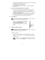
II. THE WEATHER CENTER
1. Using a straightedge, horizontally mark 3 screw positions with a pencil.
The screw positions should be spaced 3 5/8 of an inch (94mm).
2. Install 3 mounting screws (not included) into a wall within range, leaving
approximately 3/16 of an inch (5mm) extended from the wall.
3. Place the Weather Center onto the screws, using the hanging holes on the
backside. Gently pull the Weather Center down to lock the screws into
place.

17
TROUBLESHOOTING
Problem:
No reception of WWVB time signal.
Solution:
1) Wait overnight for signal.
2) Be sure Weather Center is at least 6 feet from any electrical devices, such
as televisions, computers, or other radio-controlled clocks.
3) Remove batteries for 5 minutes, reinsert and leave the unit alone
overnight without pressing buttons.
4) If there are still problems, contact La Crosse Technology.
Problem:
Hour is incorrect (minute and date are correct).
Solution:
Be sure correct time zone and daylight saving time are selected.
Problem:
The LCD is faint.
Solution:
1) Set the LCD contrast to a higher level.
2) Replace batteries.
Problem:
No outdoor temperature or humidity is displayed.
Solution:
1) Remove all batteries, reinsert into sensor first, then Weather Center.
2) Place remote sender closer to display.
3) Be sure all batteries are fresh.
4) No other interfering sources on a 433MHz frequency are being used
(such as computer monitors, TV sets, headphones, or speakers) in the
vicinity.
Note:
For problems not solved, please contact La Crosse Technology.
MAINTENANCE & CARE
• Extreme temperatures, vibrations, and shock should be avoided to prevent damage to
the units.
• Clean displays and units with a soft, damp cloth. Do not use solvents or scouring
agents—they may mark and damage the displays and casings.
• Do not submerge in water.
• Immediately remove all low powered batteries to avoid leakage and damage.
Replace with new batteries only, and of recommended size.
• Opening the casings invalidates the warranty. Do not try to repair the units. Contact
La Crosse Technology for Repairs.

18
SPECIFICATIONS
Temperature measuring range
Indoor:
32°F to 140°F with 0.2°F resolution.
(0°C to 59.9°C with 0.1°C resolution).
Outdoor:
-21°F to 140°F with 0.2°F resolution.
(-29.9°C to 59.9°C with 0.1°C
resolution).
Relative Humidity measuring range
Indoor/Outdoor: 20% to 95% with 1% resolution.
Indoor Temperature checking interval: Every 10 seconds.
Indoor Humidity checking interval: Every 20 seconds.
Outdoor Temperature/Humidity
reception:
2 times every 10 minutes.
Transmission Range: 80 feet/25m (in open space).
Power Supply
Weather Center: 3 x C, IEC LR14, 1.5V.
Sensor: 2 X AA, IEC LR6, 1.5V.
Battery life cycle: Approximately 12 months.
Recommended battery type: Alkaline.
Dimensions (L x W x H)
Weather Center: 15.59 x 1.45 x 14.46 in
(396 x 37 367.5mm).
Sensor: 3.22 x 1.69 x 6.96 in
(82 x 43 x 177mm).
WARRANTY INFORMATION
La Crosse Technology, Ltd provides a 1-year limited warranty on this product against
manufacturing defects in materials and workmanship.
This limited warranty begins on the original date of purchase, is valid only on products
purchased and used in North America and only to the original purchaser of this product.
To receive warranty service, the purchaser must contact La Crosse Technology, Ltd for
problem determination and service procedures. Warranty service can only be performed
by a La Crosse Technology, Ltd authorized service center. The original dated bill of sale
must be presented upon request as proof of purchase to La Crosse Technology, Ltd or La
Crosse Technology, Ltd’s authorized service center.
La Crosse Technology, Ltd will repair or replace this product, at our option and at no
charge as stipulated herein, with new or reconditioned parts or products if found to be
defective during the limited warranty period specified above. All replaced parts and
products become the property of La Crosse Technology, Ltd and must be returned to La
Crosse Technology, Ltd. Replacement parts and products assume the remaining original

19
warranty, or ninety (90) days, whichever is longer. La Crosse Technology, Ltd will pay all
expenses for labor and materials for all repairs covered by this warranty. If necessary
repairs are not covered by this warranty, or if a product is examined which is not in need
or repair, you will be charged for the repairs or examination. The owner must pay any
shipping charges incurred in getting your La Crosse Technology, Ltd product to a La
Crosse Technology, Ltd authorized service center. La Crosse Technology, Ltd will pay
ground return shipping charges to the owner of the product to a USA address only.
Your La Crosse Technology, Ltd warranty covers all defects in material and workmanship
with the following specified exceptions: (1) damage caused by accident, unreasonable use
or neglect (including the lack of reasonable and necessary maintenance); (2) damage
occurring during shipment (claims must be presented to the carrier); (3) damage to, or
deterioration of, any accessory or decorative surface; (4) damage resulting from failure to
follow instructions contained in your owner’s manual; (5) damage resulting from the
performance of repairs or alterations by someone other than an authorized La Crosse
Technology, Ltd authorized service center; (6) units used for other than home use (7)
applications and uses that this product was not intended or (8) the products inability to
receive a signal due to any source of interference.. This warranty covers only actual
defects within the product itself, and does not cover the cost of installation or removal from
a fixed installation, normal set-up or adjustments, claims based on misrepresentation by
the seller or performance variations resulting from installation-related circumstances.
LA CROSSE TECHNOLOGY, LTD WILL NOT ASSUME LIABILITY FOR INCIDENTAL,
CONSEQUENTIAL, PUNITIVE, OR OTHER SIMILAR DAMAGES ASSOCIATED WITH
THE OPERATION OR MALFUNCTION OF THIS PRODUCT. THIS PRODUCT IS NOT
TO BE USED FOR MEDICAL PURPOSES OR FOR PUBLIC INFORMATION. THIS
PRODUCT IS NOT A TOY. KEEP OUT OF CHILDREN’S REACH.
This warranty gives you specific legal rights. You may also have other rights specific to
your State. Some States do no allow the exclusion of consequential or incidental
damages therefore the above exclusion of limitation may not apply to you.
For warranty work, technical support, or information contact:
La Crosse Technology
2809 Losey Blvd. S.
La Crosse, WI 54601
Phone: 608.782.1610
Fax: 608.796.1020
e-mail:
support@lacrossetechnology.com
(warranty work)
sales@lacrossetechnology.com
(information on other products)
web:
www.lacrossetechnology.com

20
FCC ID: OMO-01TX (sensor), OMO-01RX (receiver)
THIS DEVICE COMPLIES WITH PART 15 OF THE FCC RULES. OPERATION IS SUBJECT TO
THE FOLLOWING TWO CONDITIONS:
1. THIS DEVICE MAY NOT CAUSE HARMFUL INTERFERENCE, AND
2. THIS DEVICE MUST ACCEPT INTERFERENCE RECEIVED, INCLUDING INTERFERENCE
THAT MAY CAUSE UNDESIRED OPERATION.
-
 1
1
-
 2
2
-
 3
3
-
 4
4
-
 5
5
-
 6
6
-
 7
7
-
 8
8
-
 9
9
-
 10
10
-
 11
11
-
 12
12
-
 13
13
-
 14
14
-
 15
15
-
 16
16
-
 17
17
-
 18
18
-
 19
19
-
 20
20


La Crosse Technology WS-8010U User manual
- Category
- Weather stations
- Type
- User manual
Ask a question and I''ll find the answer in the document
Finding information in a document is now easier with AI
Related papers
-
 La Crosse Technology WS-7212U User manual
-
La Crosse WS-7390U User manual
-
La Crosse WS-7391U User manual
-
 La Crosse Technology WS-7032U User manual
-
La Crosse Technology WS-7213U User manual
-
 La Crosse Technology WS-7014U User manual
-
La Crosse Technology P7026 User manual
-
 La Crosse Technology WS-7044U User manual
-
 La Crosse Technology WS-7078TWC User manual
-
La Crosse WS-7078UF User manual


