Extech Instruments RH101 User manual

Category
Measuring, testing & control
Type
User manual
User's Guide
Hygro-Thermometer + InfraRed Thermometer
Model RH101
RH101-en-GB_V3.2 4/15
2
Introduction
Congratulations on your purchase of the Extech Hygro-Thermometer plus InfraRed Thermometer.
This device measures relative humidity, air temperature (with probe), and surface temperature
(with the InfraRed function). The large, easy-to-read backlit LCD includes primary and secondary
displays plus numerous status indicators. The InfraRed feature includes a laser pointer for
convenient targeting. Careful use of this meter will provide years of reliable service.
Safety
Use extreme caution when the laser pointer beam is on
Do not point the beam toward anyone's eye or allow the beam
to strike the eye from a reflective surface
Do not use the laser near explosive gases or in other
potentially explosive areas
RH101-en-GB_V3.2 4/15
3
Meter Description
1. Humidity/Air Temperature Probe
2. Probe input jack
3. Laser pointer
4. IR Sensor
5. Rubber holster
6. LCD Display
7. IR thermometer measurement button
8. IR and Relative Humidity function buttons (4)
9. Air Temperature function buttons (3)
10. Probe holder
11. Power ON/OFF button
12. Backlight button
Note: The battery compartment, tilt stand, tripod mount, and probe holder removal screw are
located on the rear of the instrument
RH101-en-GB_V3.2 4/15
4
Display Layout
MAX (top of LCD): Max Hold function engaged for the Air Temperature function
HOLD (top of LCD): Data Hold function engaged for the Air Temperature function
PROBE TEMP: Reminder that the top LCD digits represent Air (Probe) Temperature
: Indicates that the laser pointer is on.
IR TEMP: Indicates that the larger LCD digits represent IR temperature measurement
MAX (bottom of LCD): Max Hold for the IR Temperature and RH function
HOLD (bottom of LCD): Data Hold for the IR Temperature function and RH function
o
C /
o
F: Temperature units of measure
%RH: Relative Humidity unit of measure
Large LCD digits at center of display for Relative Humidity and IR Temperature
Smaller LCD digits at top, right of display for Probe Temperature
: Low battery indicator
RH101-en-GB_V3.2 4/15
5
Operation
Power
Press the button to turn power on or off.
Probe Humidity and Temperature Measurements
1. Attach the probe to the meter via the jack at the top of the meter.
2. Hold the probe in the area to be tested & allow adequate time for readings to stabilize.
3. Read the Relative Humidity (center of LCD) and Probe Temperature (top of LCD).
NOTE: Do not immerse the probe in liquid; it is intended for use in air only.
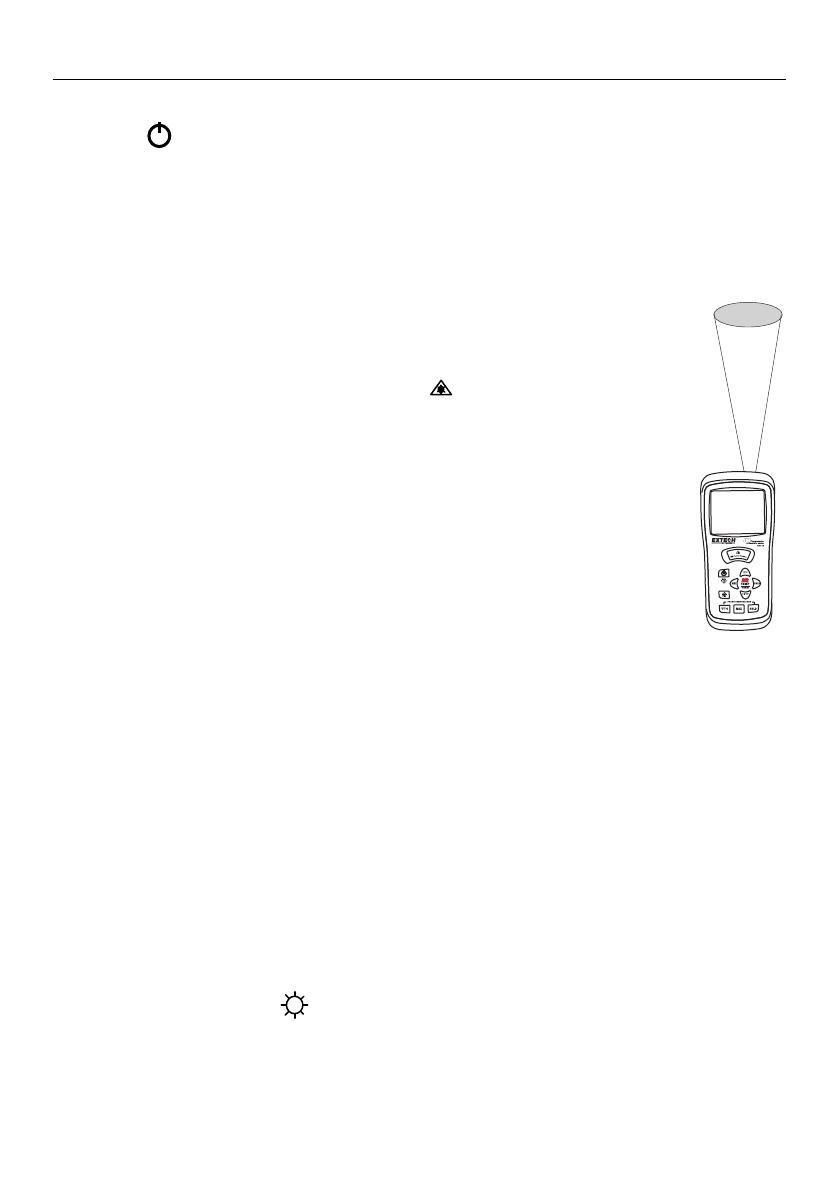
InfraRed (Non-Contact) Temperature Measurements
1. The IR sensor is located at the top of the meter.
2. Point the sensor toward the surface to be measured.
3. Press and hold the large red IR button to begin measuring the surface
temperature of a desired target. IR TEMP and will appear on the display. The
laser pointer will switch on to help aim the meter.
4. The measured IR surface temperature will appear at the center of the LCD (larger
digits). The temperature displayed is the temperature of the area within the spot.
5. When the red IR button is released, the laser pointer will switch off and the
reading will freeze (data hold) on the display for approx 10 seconds.
6. Note that the probe (Air Temperature wand) continues to monitor temperature
during IR tests and its temperature is displayed on the top of the LCD (smaller
digits).
7. After approx. 10 secs. the meter defaults to the Humidity and Air Temperature
display.
Automatic Power OFF
To conserve battery life the meter automatically shuts off after 10 minutes.
o
F/
o
C buttons
The Air Temperature and the IR Temperature units can be selected by the user. For Air
Temperature, press the
o
F/
o
C button on the bottom left. For the IR temperature units, press the
o
F/
o
C button at the center of the meter.
Data Hold Buttons
Displays can be held (frozen) at any time by pressing the HOLD button. For Air Temperature, use
the HOLD button on the bottom right. For IR Temperature and for Relative Humidity, use the HOLD
button on the right center of the meter. Press HOLD again to exit the mode. Note that in IR
temperature mode Data Hold is automatically engaged when the red IR button is released.
MAX Buttons
Press the MAX button (bottom of meter for Air Temperature; center of meter for IR temperature and
Relative Humidity) to display only the highest reading. The displayed measurement will now only
change when a higher reading is detected. Press the MAX button again to exit this mode.
Backlight Press the backlight button to turn the light on. Press again to turn it off.
IR
Spot
RH101-en-GB_V3.2 4/15
6
InfraRed Measurement Considerations
When taking IR measurements the meter automatically compensates for ambient temperature
changes. Note that it may take up to 30 minutes to adjust to extremely wide ambient changes.
Low temperature measurements quickly followed by high temperature measurements may
require several minutes to stabilize as a result of the IR sensor cooling process.
If the surface of the object under test is covered with frost, oil, grime, etc., clean before taking
measurements.
If an object's surface is highly reflective apply masking tape or flat black paint before measuring.
Steam, dust, smoke, etc. can obstruct measurements.
To find a hot spot, aim the meter outside the area of interest then scan across (in an up and
down motion) until the hot spot is located.
IR Theory
IR thermometers measure the surface temperature of an object. The meter’s optics sense emitted,
reflected, & transmitted energy that is collected and focused onto the meter’s detector. The meter’s
circuitry translates this information into an LCD reading.
IR Field of View
Ensure that the desired target is larger than the spot size as shown in the diagram below. As the
distance from an object increases, the spot size of the area measured by the meter becomes larger.
The meter’s field of view ratio is 8:1, meaning that if the meter is 8 inches from the target, the
diameter (spot) of the object under test must be at least 1 inch. Other distances are shown below in
the field of view diagram.
Distance to Object in inches
Diameter of S
p
ot in inches
0.75”
1”
1.25”
6”
8”
10”
12”
1.5”
RH101-en-GB_V3.2 4/15
7
Maintenance
Cleaning and storage
1. The meter should be cleaned with a damp cloth and mild detergent when necessary. Do not use
solvents or abrasives.
2. Store the meter in an area with moderate temperature and humidity.
Battery Replacement
The battery symbol appears on the lower right of the LCD when the 9V battery needs to be
replaced.
Replace the 9V battery as follows:
1. Turn the meter off and disconnect the air temperature probe.
2. Remove the large flat-head screw on the rear of the meter to remove the probe holder.
3. Remove the rubber holster that surrounds the entire meter by pulling it over the top of the meter.
4. Remove the small Phillips head screw on the rear of the meter.
5. Open the battery compartment and replace the 9V battery.
6. Re-assemble the meter before operating.
Never dispose of used batteries or rechargeable batteries in household waste.
As consumers, users are legally required to take used batteries to appropriate
collection sites, the retail store where the batteries were purchased, or wherever
batteries are sold.
Disposal: Do not dispose of this instrument in household waste. The user is obligated to take end-of-
life devices to a designated collection point for the disposal of electrical and electronic equipment.
Other Battery Safety Reminders
o Never dispose of batteries in a fire. Batteries may explode or leak.
o Never mix battery types. Always install new batteries of the same type.
WARNING: To avoid electric shock, do not operate the meter until the battery cover is in place and
fastened securely.
NOTE:: If your meter does not work properly, check the fuses and batteries to make sure that they are
still good and that they are properly inserted.
Calibration
A humidity calibration adjustment is located in the battery compartment.
1. Remove the battery door and move the battery to one side.
2. Place the humidity probe in a humidity chamber or humidity calibration bottle
and wait 20 minutes
3. Turn the meter on and turn the adjustment until the humidity reading on the
display agrees with the calibration source.
Battery
Compartment
Cal
Adjust
RH101-en-GB_V3.2 4/15
8
Specifications
Display Dual LCD with Backlight and status indicators
Sensor Type Humidity: Precision capacitance sensor
Temperature: Thermistor (probe) and InfraRed
Response Time IR Temperature: 0.5 seconds; Probe Temperature and Relative
Humidity: 3 minutes
Accuracy note Accuracy is specified for the following ambient temperature range: 18 to
28°C (64 to 82°F)
Sampling Rate 2.5 samples per second
InfraRed Emissivity 0.95 (fixed)
IR Field of View D/S = Approx. 8:1 ratio (D = distance, S = spot)
Laser power Less than 1mW
IR Spectral Response 6 to 14 m (wavelength)
Operating Conditions 0 to 50
o
C (32 to 122
o
F); < 80% RH non-condensing
Storage Conditions -10 to 60
o
C (14 to 140
o
F); <80% RH non-condensing
Power Supply 9V Battery with auto power off (after 10 minutes)
Battery Life Approx. 24 hours (if Backlight and Laser are used continuously the
battery life is reduced to 2 to 3 hours approx.)
Dimensions / Weight 150 x 72 x 35mm (5.9 x 2.8 x 1.4”); 235g (8.3 oz)
Patent Notice U.S. Patent 7168316
Emissivity
Most organic materials and painted or oxidized surfaces have an emissivity of 0.95 (fixed setting in
the model RH101). Inaccurate readings will result when measuring shiny or polished surfaces. To
compensate, cover the surface under test with masking tape or flat black paint. Allow time for the
tape to reach the same temperature as the material underneath then measure the temperature of
the tape or the painted surface.
Function Range and Resolution Accuracy
Humidity 10.0 to 95.0% RH ± 3.5% RH
Air Temperature -20 to 60
o
C (-4 to 140
o
F) ± 2.0
o
C (± 3.0
o
F)
IR Temperature -50.0 to -20.0
o
C (-58.0 to -4.0
o
F) ± 5
o
C (± 9
o
F)
-20.0 to 93.3
o
C (-4.0 to 199.9
o
F)
± 2% of rdg or ± 2
o
C (± 4
o
F)
93
o
C to 204
o
C (200 to 400
o
F)
204
o
C to 500
o
C (400 to 932
o
F) ± 3% of rdg
RH101-en-GB_V3.2 4/15
9
Thermal Emissivity Table for Common Materials
Material Emissivity
Asphalt 0.90 to 0.98
Concrete 0.94
Cement 0.96
Sand 0.90
Earth 0.92 to 0.96
Water 0.67
Ice 0.96 to 0.98
Snow 0.83
Glass 0.85 to 1.00
Ceramic 0.90 to 0.94
Marble 0.94
Plaster 0.80 to 0.90
Mortar 0.89 to 0.91
Brick 0.93 to 0.96
Cloth (black) 0.98
Human skin 0.98
Lather 0.75 to 0.80
Charcoal (powder) 0.96
Lacquer 0.80 to 0.95
Lacquer (matt) 0.97
Rubber (black) 0.94
Plastic 0.85 to 0.95
Timber 0.90
Paper 0.70 to 0.94
Chromium oxides 0.81
Copper Oxides 0.78
Iron Oxides 0.78 to 0.82
Textiles 0.90
Copyright©20112014FLIRSystems,Inc.
Allrightsreservedincludingtherightofreproductioninwholeorinpartinanyform
ISO9001Certified
www.extech.com
  • Page 1 1
  • Page 2 2
  • Page 3 3
  • Page 4 4
  • Page 5 5
  • Page 6 6
  • Page 7 7
  • Page 8 8
  • Page 9 9

Extech Instruments RH101 User manual

Category
Measuring, testing & control
Type
User manual

Ask a question and I''ll find the answer in the document

Finding information in a document is now easier with AI