Page is loading ...


Copyright © 2004 Altera Corporation. All rights reserved. Altera, The Programmable Solutions Company, the stylized Altera logo, specific device des-
ignations, and all other words and logos that are identified as trademarks and/or service marks are, unless noted otherwise, the trademarks and
service marks of Altera Corporation in the U.S. and other countries. All other product or service names are the property of their respective holders. Al-
tera products are protected under numerous U.S. and foreign patents and pending applications, maskwork rights, and copyrights. Altera warrants
performance of its semiconductor products to current specifications in accordance with Altera's standard warranty, but reserves the right to make
changes to any products and services at any time without notice. Altera assumes no responsibility or liability arising out of the ap-
plication or use of any information, product, or service described herein except as expressly agreed to in writing by Altera
Corporation. Altera customers are advised to obtain the latest version of device specifications before relying on any published in-
formation and before placing orders for products or services.
Printed on recycled paper
ii Altera Corporation

Altera Corporation iii
Contents
Chapter 1. About the EthernetBlaster Communications Cable
Introduction ............................................................................................................................................ 1–1
Supported Devices ........................................................................................................................... 1–1
Power Requirements ........................................................................................................................ 1–2
Software Requirements ................................................................................................................... 1–2
Connections ....................................................................................................................................... 1–2
Static & Dynamic IP Addressing .................................................................................................... 1–4
Cable Setup ............................................................................................................................................. 1–4
Remote Connection via Network Using Default Factory Settings ............................................ 1–5
Direct Connection to a Computer Using Default Factory Settings ........................................... 1–8
Configuring the EthernetBlaster Hardware to Use Static IP Addressing .............................. 1–11
Configuring the EthernetBlaster Hardware to Use Dynamic IP Addressing ....................... 1–12
Setting Up the EthernetBlaster Hardware in the Quartus II Software ................................... 1–13
Removing the EthernetBlaster Hardware from the Quartus II Software .............................. 1–15
Chapter 2. EthernetBlaster Communications Cable Administration
Introduction ............................................................................................................................................ 2–1
Managing Passwords ............................................................................................................................ 2–1
Changing the Administrative Password ...................................................................................... 2–2
Changing the Quartus II Remote Connection Password ........................................................... 2–3
Resetting the Hardware ........................................................................................................................ 2–4
Firmware Upgrade ................................................................................................................................ 2–5
Chapter 3. EthernetBlaster Communications Cable Specifications
Overview ................................................................................................................................................. 3–1
EthernetBlaster Hardware Connections ............................................................................................. 3–1
Voltage Requirements ..................................................................................................................... 3–1
EthernetBlaster Ethernet Jack Connection .................................................................................... 3–2
EthernetBlaster Plug Connection ................................................................................................... 3–2
Circuit Board Header Connection ................................................................................................. 3–3
Operating Conditions ........................................................................................................................... 3–4
References ............................................................................................................................................... 3–5
Revision History .................................................................................................................................... 3–6
How to Contact Altera .......................................................................................................................... 3–6

iv Altera Corporation
EthernetBlaster Communications Cable User Guide
Contents

Altera Corporation 1–1
December 2004
Chapter 1. About the
EthernetBlaster
Communications Cable
Introduction
The EthernetBlaster communications cable connects to a standard
Ethernet network port with an RJ-45 connector. This cable communicates
with client systems using the TCP/IP protocol and supports both static
and dynamic IP addressing. The EthernetBlaster communications cable
can be plugged into an existing 10/100 Base-T Ethernet network to
communicate with clients remotely or interfaced directly via a standard
10/100 Base-T Ethernet port using a crossover cable. Because design
changes are downloaded directly to the device, prototyping is easy and
you can accomplish multiple design iterations in quick succession.
Harnessing the power of an Ethernet network, multiple users can
remotely access Altera
®
devices, bringing a new level of productivity to
prototyping and debugging.
Supported Devices
You can use the EthernetBlaster communications cable to download
configuration data to the following Altera devices:
■ Stratix
®
series FPGAs
■ Cyclone
™
series FPGAs
■ MAX
®
series CPLDs
■ APEX
™
series FPGAs
■ ACEX
®
1K FPGAs
■ Mercury
™
FPGAs
■ FLEX
®
series FPGAs
■ Excalibur
™
FPGAs
You can perform in-system programming of the following devices:
■ Advanced configuration devices, including EPC2, EPC4, EPC8,
EPC16, and EPC1441 devices.
■ Serial configuration devices, including EPCS1, EPCS4, EPCS16, and
EPCS64 devices.
In addition, the EthernetBlaster communications cable supports target
systems using 5.0-V TTL, 3.3-V LVTTL/LVCMOS, and single-ended I/O
standards from 3.3 V down to 1.5 V.

1–2 Altera Corporation
EthernetBlaster Communications Cable User Guide December 2004
Introduction
Power Requirements
The EthernetBlaster communications cable requires between 1.5 V and
5.0 V from the target circuit board, and 12.0 VDC (0.875A) input power
for the EthernetBlaster V
CCSUPPLY
(a 12.0 VDC wall transformer is
supplied).
The EthernetBlaster V
CC(TARGET)
pin must be connected to the appropriate
voltage for the device being programmed. The pull-up resistors on the
target circuit board for the configuration/programming signals must be
connected to the same power supply as the EthernetBlaster V
CC(TARGET)
.
Software Requirements
The EthernetBlaster communications cable is available on the Windows,
UNIX, and Linux platforms, including the following:
■ Windows NT 4.0
■ Windows 2000
■ Windows XP
■ Solaris 2.6
■ Solaris 2.7/7
■ Solaris 8/9
■ Red Hat Linux version 7.3
■ Red Hat Linux version 8.0
■ Red Hat Enterprise Linux WS 3.0
■ HP-UX version 11.0
Use the Quartus
®
II software beginning with version 4.0 to configure your
device. The EthernetBlaster communications cable also supports the
following tools:
■ Quartus II Programmer (for programming and configuration),
which you can run within the Quartus II software or as a stand-alone
version
■ Quartus II SignalTap II Logic Analyzer (for logic analysis), which
you can run within the Quartus II software or as a stand-alone
version
■ Nios
®
II IDE (for software downloading and debugging)
■ Nios II IDE Flash Programmer (for programming Flash devices)
Connections
The EthernetBlaster communications cable houses an Ethernet port on
one side and a 10-pin female target port on the opposite side. The
Ethernet port side contains an Ethernet port, a reset button, and a DC12V

Altera Corporation 1–3
December 2004 EthernetBlaster Communications Cable User Guide
About the EthernetBlaster Communications Cable
jack. The target port side includes the 10-pin female target port and LED
status light. The base of the cable includes the MAC address and host
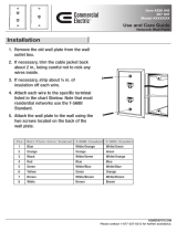
name. Figure 1–1 shows the side and base views of the hardware.
Figure 1–1. EthernetBlaster Communications Cable Ethernet Port, Target Port, and Base Views
The status LED on the target port side of the cable displays the operation
status of the EthernetBlaster communications cable. See Table 1–1 for a
description of each LED status modes.
TARGET
STATUS
ETHERNET
DC12V
Status LED
Target Port View
Ethernet Port View
Base View
Ethernet Port 10-Pin Target Port
DC12V Jack
Machine Reset
Ethernet Blaster
Copyright 2004 Altera Corporation
D0:07:ED:05:XX:XX
Host Name: acebXXXX
MAC Address
Host Name
Table 1–1. Status LED Modes
Status LED Status Description
Red-Green Power on, reset
Green, blinking Cable initialization
Green, steady Cable ready
Blue, blinking Downloading data to target printed circuit board

1–4 Altera Corporation
EthernetBlaster Communications Cable User Guide December 2004
Cable Setup
Static & Dynamic IP Addressing
The EthernetBlaster communications cable supports both static IP and
dynamic IP addressing, the latter by means of Dynamic Host
Configuration Protocol (DHCP). By default, the EthernetBlaster cable is
configured at the factory to use dynamic IP addressing. Upon power up,
the cable attempts to obtain an IP address from your network DHCP
server. The Status LED is green and blinking while the network address
is being obtained and the cable is initializing. This process may take up to
two minutes.
When an IP address is obtained and the cable is ready to use, the status
LED emits a steady green light. If the attempt to obtain an IP address is
unsuccessful (the DHCP server may be down or absent), the cable
switches to static IP addressing. The default IP address is configured to
192.168.0.50. If static IP addressing is used, you must configure your
computer to an IP address in the same subnet as the cable to communicate
with it. The default setting requires your address to be in the 192.168.0.X
network domain.
1 Refer to your operating system manual or contact your network
administrator to verify that your network supports DHCP
services and for instruction on how to change your IP address.
To maintain your computer’s IP address and change the
EthernetBlaster communications cable’s default IP address, see
“Configuring the EthernetBlaster Hardware to Use Static IP
Addressing” on page 1–11.
The EthernetBlaster communications cable includes a self-hosted
administrative web page, allowing you to configure various aspects of
cable operation. The following section describes how to access this web
page based on your mode of connection.
Cable Setup
This section describes how to install and set up the EthernetBlaster
communications cable for device configuration or programming
including the following setups:
■ Remote Connection via Network Using Default Factory Settings
■ Direct Connection to a Computer Using Default Factory Settings
■ Configuring the EthernetBlaster Hardware to Use Static IP
Addressing
■ Configuring the EthernetBlaster Hardware to Use Dynamic IP
Addressing
■ Setting Up the EthernetBlaster Hardware in the Quartus II Software
■ Removing the EthernetBlaster Hardware from the Quartus II
Software

Altera Corporation 1–5
December 2004 EthernetBlaster Communications Cable User Guide
About the EthernetBlaster Communications Cable
1 For plug and header dimensions, pin names, and operating
conditions, see Chapter 3, “EthernetBlaster Communications
Cable Specifications.”
Remote Connection via Network Using Default Factory Settings
Use the following steps to connect remotely to the EthernetBlaster
communications cable:
1 These steps assume no changes have been made to the default
factory settings.
1. Disconnect the power cable from the circuit board.
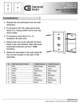
2. Plug one end of a standard CAT 5 UTP 4-pair patch cable into the
Ethernet jack on the EthernetBlaster communications cable, and the
other end into a network port of a switch, router, or hub. See
Figure 1–2 below.
Figure 1–2. Remote Connection via Network
3. Connect the 10-pin female plug of the flexible, PCB-shielded cable
labeled “BLASTER SIDE” to the 10-pin female target port on the
Ethernet communications cable, and the 10-pin female plug of the
cable labeled “TARGET SIDE” to the 10-pin male header on the
target circuit board as shown in Figure 1–3 on page 1–6.
Switch, Router, or Hub
ETHERNET
ETHERNET
DC12V
EthernetBlaster Communications Cable,
Ethernet Port Side View
CAT 5 UTP
Standard Cable
Ethernet Jack
CAT 5 UTP
Standard Cable
Ethernet Connector
EIA/TIA 568B
1
.
.
.
8
Pin EIA/TIA 568B Wire Color
1
2
3
4
5
6
7
8
White with Orange Stripe
Orange with White Stripe
White with Green Stripe
Blue with White Stripe
White with Blue Stripe
Green with White Stripe
White with Brown Stripe
Brown with White Stripe
Ethernet
Jack

1–6 Altera Corporation
EthernetBlaster Communications Cable User Guide December 2004
Cable Setup
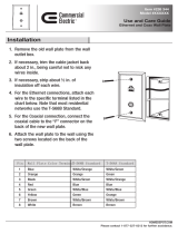
Figure 1–3. Connecting the EthernetBlaster Communications Cable to the Target Circuit Board
4. Plug the supplied 12.0 VDC wall transformer into a power outlet
and then into the EthernetBlaster communications cable.
1 Always connect the network patch cable as instructed in
step 2 before connecting the power cord. This allows the
EthernetBlaster communications cable to obtain a DHCP
address (if your network is configured to do so). Wait until
the Status LED emits a steady green light.
5. Reconnect the power cable to the circuit board to reapply power.
6. If your network supports DHCP, see step 7 on the following page
for configuration instructions. If your network does not support
DHCP, see step 8 on the following page for configuration
instructions.
7. If your network supports DHCP, you can access the EthernetBlaster
Configuration administrative web page using a web browser with
the hostname as the address. The hostname is located on the label
on the base of the EthernetBlaster communications cable as shown
in Figure 1–4 on page 1–7.
10-pin Female Connector (connects
to the target printed circuit board
10-pin male header)
Pin 1 of the Flexible PCB
Shielded-Cable Facing this Side
P
I
N
1
T
A
R
G
E
T
B
L
A
S
T
E
R
S
I
D
E
S
I
D
E
EthernetBlaster
DC12V
ETHERNET

Altera Corporation 1–7
December 2004 EthernetBlaster Communications Cable User Guide
About the EthernetBlaster Communications Cable
Figure 1–4. MAC Address & Host Name
Browse to http://<host name> and specify the host name from the
label on the base of your EthernetBlaster communications cable. The
EthernetBlaster login window opens.
1 Note that the last 4 digits of the MAC address match the last
4 digits of the host name on the label on the base of your
EthernetBlaster cable.
or
If you know the IP address obtained by the EthernetBlaster
communications cable, you can access the administrative web page
by entering this address in your browser.
1 See step 9 on the following page for system configuration
details.
8. If your network does not support DHCP, you must configure your
computer to an address in the 192.168.0.X network domain, and
then browse to http://192.168.0.50. See step 9 on the following page
for system configuration details.
1 Refer to your operating system manual or contact your
network administrator for instruction on how to change
your IP address.
EthernetBlaster Communications Cable Bottom View
Ethernet Blaster
Copyright 2004 Altera Corporation
D0:07:ED:05:XX:XX
Host Name: acebXXXX
Use the hostname as the address
to access the EthernetBlaster
communications cable
configuration administrative
web page.
The last 4 digits of the MAC address
are the same as the last 4 digits of
the host name.

1–8 Altera Corporation
EthernetBlaster Communications Cable User Guide December 2004
Cable Setup
1 To maintain your computer’s IP address and change the
EthernetBlaster communications cable default IP address,
see “Configuring the EthernetBlaster Hardware to Use
Static IP Addressing” on page 1–11.
9. In the EthernetBlaster login window, enter admin as the login and
password as the default password. The EthernetBlaster Status
page opens, displaying the status of your EthernetBlaster
communications cable, including the current IP address. See
Figure 1–5.
Figure 1–5. EthernetBlaster Configuration Administrative Page
1 See Chapter 2, “Managing Passwords,” to manage your
password after initial login.
10. Proceed to “Setting Up the EthernetBlaster Hardware in the
Quartus II Software” on page 1–13 to set up your hardware in the
Quartus II software.
Direct Connection to a Computer Using Default Factory Settings
The EthernetBlaster communications cable can be connected directly to
the network port of a computer. This setup does not allow remote users
to access the EthernetBlaster communications cable.
Use the following steps to connect the EthernetBlaster communications
cable directly to your system:

Altera Corporation 1–9
December 2004 EthernetBlaster Communications Cable User Guide
About the EthernetBlaster Communications Cable
1 These steps assume no changes have been made to the
default factory settings.
1. Disconnect the power cable from the circuit board.
2. Plug the EIA/TIA 568B connector of a crossover CAT 5 UTP 4-pair
patch cable into the Ethernet jack on the EthernetBlaster
communications cable, and the EIA/TIA 568A connector into your
computer. See Figure 1–6 below.
Figure 1–6. Direct Connection to a Computer Using a Crossover Cable
or
Plug one end of a standard CAT5 UTP 4-pair patch cable into the
Ethernet jack on the EthernetBlaster communications cable, and add
a crossover adapter to the other end of the cable. Plug the adapter
end of the cable into your computer. See Figure 1–7 on page 1–10.
Computer
ETHERNET
ETHERNET
DC12V
EthernetBlaster Communications Cable,
Ethernet Port Side View
CAT 5 UTP
Crossover Cable
Ethernet Jack
Ethernet EIA/TIA 568A Connector
Connected to the Computer
Pin EIA/TIA 568A Wire Color
1
2
3
4
5
6
7
8
White with Green Stripe
Green with White Stripe
White with Orange Stripe
Blue with White Stripe
White with Blue Stripe
Orange with White Stripe
White with Brown Stripe
Brown with White Stripe
Ethernet
Jack
CAT 5 UTP Crossover Cable
1
. . .
8
Ethernet EIA/TIA 568B Connector Connected
to the EthernetBlaster Communications Cable
Pin EIA/TIA 568B Wire Color
1
2
3
4
5
6
7
8
White with Orange Stripe
Orange with White Stripe
White with Green Stripe
Blue with White Stripe
White with Blue Stripe
Green with White Stripe
White with Brown Stripe
Brown with White Stripe
CAT 5 UTP Crossover Cable
1
. . .
8

1–10 Altera Corporation
EthernetBlaster Communications Cable User Guide December 2004
Cable Setup
Figure 1–7. Direct Connection to a Computer Using a Standard Cable and a Crossover Adapter
3. Connect the 10-pin female plug of the flexible, PCB-shielded cable
labeled “BLASTER SIDE” to the 10-pin female target port on the
Ethernet communications cable, and the 10-pin female plug of the
cable labeled “TARGET SIDE” to the 10-pin male header on the
target circuit board as shown in Figure 1–3 on page 1–6.
4. Plug the supplied 12.0 VDC wall transformer into a power outlet
and then into the EthernetBlaster communications cable.
5. Reconnect the power cable to the target circuit board to reapply
power.
6. To access the EthernetBlaster Status web page, configure your
computer to an address in the 192.168.0.X network domain and then
browse to http://192.168.0.50. The EthernetBlaster login window
opens.
1 Refer to your operating system manual or contact your
network administrator for instruction on how to change
your IP address.
To maintain your computer’s IP address and change the
EthernetBlaster communications cable default IP address, see
“Configuring the EthernetBlaster Hardware to Use Static IP
Addressing” on page 1–11.
Computer
ETHERNET
ETHERNET
ETHERNET
DC12V
EthernetBlaster Communications Cable,
Ethernet Port Side View
EIA/TIA 568B
Connector
CAT 5 UTP
Standard Cable
Ethernet Jac
k
EIA/TIA 568B
Connector
Ethernet
Jack
Crossover
Adapter

Altera Corporation 1–11
December 2004 EthernetBlaster Communications Cable User Guide
About the EthernetBlaster Communications Cable
7. In the EthernetBlaster login window, enter admin as the login and
password as the default password. The EthernetBlaster Status
page opens displaying the status of your EthernetBlaster
communications cable including the current IP address. See
Figure 1–5.
1 See Chapter 2, “Managing Passwords,” to manage your
password after initial login.
8. To set up the EthernetBlaster communications cable in the
Quartus II software, see “Setting Up the EthernetBlaster Hardware
in the Quartus II Software” on page 1–13.
Configuring the EthernetBlaster Hardware to Use Static IP
Addressing
By default, the EthernetBlaster communications cable is factory
configured to use dynamic IP addressing.
1 Depending on your connection mode, this section assumes that
you have completed the steps in “Remote Connection via
Network Using Default Factory Settings” on page 1–5, or
“Direct Connection to a Computer Using Default Factory
Settings” on page 1–8.
To configure your cable to use static IP addressing and complete your
remote connection, follow the directions below:
1. Open the EthernetBlaster Status page.
2. Click the Change Settings tab and select Static IP from the
Connection Type menu. Enter the desired IP address and other
appropriate data in the settings fields. See Figure 1–8 on page 1–12.
1 Contact your network administrator if you do not know the
settings to complete the Change Settings page.

1–12 Altera Corporation
EthernetBlaster Communications Cable User Guide December 2004
Cable Setup
Figure 1–8. EthernetBlaster Change Settings Page
3. Click Apply. The EthernetBlaster communications cable
automatically restarts. When the status LED returns to a steady
green state, the EthernetBlaster communications cable has
successfully restarted and can now be added to the Quartus II
software. See “Setting Up the EthernetBlaster Hardware in the
Quartus II Software” on page 1–13.
Configuring the EthernetBlaster Hardware to Use Dynamic IP
Addressing
To configure the EthernetBlaster communications cable to use dynamic
IP addressing, follow the directions below:
1 Depending on your connection mode, this section assumes that
you have completed the steps in “Remote Connection via
Network Using Default Factory Settings” on page 1–5, or
“Direct Connection to a Computer Using Default Factory
Settings” on page 1–8.
1. Open the EthernetBlaster Status page.

Altera Corporation 1–13
December 2004 EthernetBlaster Communications Cable User Guide
About the EthernetBlaster Communications Cable
2. Click the Change Settings tab and select DHCP from the
Connection Type menu. See Figure 1–8 below.
Figure 1–9. EthernetBlaster Change Settings Page
1 Contact your network administrator if you do not know the
settings to complete the Change Settings page.
3. Click Apply. The EthernetBlaster communications cable
automatically restarts. When the status LED returns to a steady
green state, the EthernetBlaster communications cable has
successfully restarted and can now be added to the Quartus II
software. See “Setting Up the EthernetBlaster Hardware in the
Quartus II Software” on page 1–13.
Setting Up the EthernetBlaster Hardware in the Quartus II
Software
Use the following steps to set up the EthernetBlaster communications
cable in the Quartus II software.
1. Start the Quartus II software.

1–14 Altera Corporation
EthernetBlaster Communications Cable User Guide December 2004
Cable Setup
2. Choose Programmer (Tools menu).
3. Click Hardware Setup. The Hardware Settings tab of the Hardware
Setup dialog box is displayed.
4. Click Add Hardware. The Add Hardware dialog box is displayed.
Select EthernetBlaster and click Auto Detect.
1 The server name list is automatically populated with the
EthernetBlaster communications cable detected on your
subnet if Auto Detect is selected. However, if the cable is
not on your subnet, you must manually type the name or IP
address of the EthernetBlaster cable in the Server Name
field of the Add Hardware dialog box.
If you are using a direct connection to your computer, type
192.168.0.50 in the Server Name field.
5. Type the server password in the Server password field (“password”
is the factory default), and click OK.
6. EthernetBlaster is now visible in the Available hardware items list
of the Hardware Setup dialog box, as shown in Figure 1–10 below.
Figure 1–10. Hardware Setup Dialog Box
7. Click Close to close the Hardware Setup dialog box.

Altera Corporation 1–15
December 2004 EthernetBlaster Communications Cable User Guide
About the EthernetBlaster Communications Cable
8. In the Mode list, select the desired mode (Programmer window).
Table 1–2 describes each mode.
1 The EthernetBlaster communications cable supports the
Joint Test Action Group (JTAG), Passive Serial
Programming, and Active Serial modes.
Removing the EthernetBlaster Hardware from the Quartus II
Software
Changes to the EthernetBlaster communications cable setup, including
password change and IP addressing mode change, necessitate removal of
the cable from the Quartus II Programmer Hardware setup on client
systems, followed by adding the cable back into the Quartus II
Programmer Hardware setup. To remove the EthernetBlaster
communications cable from the Quartus II Programmer hardware setup,
follow the instructions below.
1. Start the Quartus II software.
2. Choose Programmer (Tools menu).
3. Click Hardware Setup. The Hardware Settings tab of the Hardware
Setup dialog box is displayed.
4. Click JTAG Settings. The JTAG Settings dialog box is displayed.
Select the corresponding hostname or IP address of the
EthernetBlaster hardware to remove. Click Remove Server.
Table 1–2. Programming Modes
Mode Mode Description
Joint Test Action Group (JTAG) Programs or configures all Altera devices
supported by the Quartus II software, excluding
FLEX 6000 devices.
In-Socket Programming Not supported by the EthernetBlaster cable.
Passive Serial Programming Configures all Altera devices supported by the
Quartus II software, excluding the following
devices: MAX 3000 and MAX 7000 devices,
advanced configuration devices, and serial
configuration devices.
Active Serial Programming Programs a single EPCS1, EPCS4, EPCS16,
or EPCS64 serial configuration device.

1–16 Altera Corporation
EthernetBlaster Communications Cable User Guide December 2004
Cable Setup
1 See “Setting Up the EthernetBlaster Hardware in the
Quartus II Software” on page 1–13 for instructions to add
the EthernetBlaster communications cable back into the
Quartus II Programmer Hardware setup.
f For details about programming devices and creating secondary
programming files, see the “Programming & Configuration” chapter of
the Introduction to Quartus II Manual.
For further information, see the Programming module of the Quartus II
online tutorial.
For further information, refer to the following topics in the Quartus II
online Help:
■ Changing the Hardware Setup
■ Programmer Introduction
■ Overview: Working with Chain Description Files
■ Overview: Converting Programming Files
/