Garmin AS_350B2/B3 Owner's manual

Category
GPS receiver modules
Type
Owner's manual

This manual is also suitable for

190-00792-13 Rev 1 RFMS, Eurocopter AS350B2, B3 G500H System
Page 2 of 25 FAA APPROVED
LOG OF REVISIONS
Page
Revision
Number
Date
Number
Description
FAA Approved
1 05/05/2014 All Complete Supplement See page 1
RFMS, Eurocopter AS350B2, B3 G500H System 190-00792-13 Rev 1
FAA APPROVED Page 3 of 25
TABLE OF CONTENTS
SECTION 1. GENERAL ...................................................................... 5
1.1 System Description ....................................................... 5
1.2 System Power Sources .................................................. 6
1.3 Navigation Sources ....................................................... 6
1.4 Helicopter Synthetic Vision Technology (Optional) .... 6
1.5 Audio Panel .................................................................. 8
1.6 Interfaced Equipment .................................................... 8
1.7 Traffic Display and Control (Optional) ........................ 9
1.8 XM Data link (Optional)............................................... 9
1.9 Video Input (Optional).................................................. 9
1.10 Iridium Data link (Optional) ......................................... 9
1.11 Radar Altimeter (Optional) ........................................... 9
1.12 Database Cards ........................................................... 10
1.13 System Description ..................................................... 10
1.14 Pitot-Static System ...................................................... 10
SECTION 2. LIMITATIONS ............................................................. 12
2.1 Types of Operation ..................................................... 12
2.2 Cockpit Reference & Pilot’s Guides ........................... 12
2.3 System Software Requirements .................................. 12
2.4 Databases .................................................................... 13
2.5 AHRS Operational Area ............................................. 13
2.6 AHRS Operation ......................................................... 13
2.7 Maximum Airspeed .................................................... 14
2.8 Navigation Angle ........................................................ 14
2.9 Course Pointer Auto Slewing ..................................... 14
2.10 Helicopter Synthetic Vision Technology (HSVT) ...... 14
2.11 Terrain and Obstacle Display ..................................... 15
2.12 Datalinked Weather Display ....................................... 15
2.13 Traffic Display ............................................................ 15
2.14 Equipment Requirements ............................................ 15
2.15 Placards ....................................................................... 16
SECTION 3. EMERGENCY PROCEDURES ................................... 17
190-00792-13 Rev 1 RFMS, Eurocopter AS350B2, B3 G500H System
Page 4 of 25 FAA APPROVED
3.1
Loss of Electrical Power ............................................. 17
3.2 Malfunction Indications and Procedures..................... 17
SECTION 4. NORMAL PROCEDURES .......................................... 22
4.1 PFD Knob & PFD Soft Keys ...................................... 22
4.2 MFD Knobs & MFD Soft Keys .................................. 22
4.3 Helicopter Synthetic Vision Technology (HSVT) ...... 23
4.4 HSVT Terrain ............................................................. 23
4.5 Altitude Alerter ........................................................... 23
SECTION 5. PERFORMANCE ......................................................... 24
SECTION 6. WEIGHT AND BALANCE ......................................... 25
TABLE OF FIGURES
Figure 1-1- GDU 620 PFD/MFD Displays ............................................ 5
Figure 1-2- Typical HSVT Display ....................................................... 7
Figure 1-3 G500H Flight Display System Block Diagram ............... 11
RFMS, Eurocopter AS350B2, B3 G500H System 190-00792-13 Rev 1
FAA APPROVED Page 5 of 25
SECTION 1. GENERAL
1.1 System Description
The G500H Flight Display System consists of a Primary Flight Display (PFD)
and Multi- Function Display (MFD) housed in a single Garmin Display Unit
(GDU 620), an Air Data Computer (GDC 74H ADC) and Attitude and Heading
Reference Systems (GRS 77H AHRS). The G500H interfaces with a Garmin
GNS 400W, 500W, or 480 series GPS/WAAS navigator and an audio panel.
Optionally, the G500H may interface with other systems installed in the
rotorcraft including a Garmin GTX330 transponder, TAS traffic system, GDL
69(A) satellite data link, video sources, radar altimeter and GSR 56 Iridium data
link.
The primary function of the PFD is to provide attitude, heading, air data and
navigation information (from GNS units) to the pilot. The primary function of
the MFD is to display supplemental data including mapping, terrain, video,
charts, and flight plan information.
Figure 1-1- GDU 620 PFD/MFD Displays
190-00792-13 Rev 1 RFMS, Eurocopter AS350B2, B3 G500H System
Page 6 of 25 FAA APPROVED
The standby instruments (airspeed, altimeter and magnetic compass) are
completely independent from the PFD and will continue to operate in the event
the PFD is inoperative. These standby instruments should be included in the
pilot’s normal instrument scan and must be utilized if the PFD data is in
question.
1.2 System Power Sources
The G500H system depends on electrical power to function. The Garmin
Display Unit (GDU), Attitude and Heading Reference System (AHRS), and Air
Data Computer (ADC) are connected to the aircraft main bus.
The major components of the G500H are circuit breaker protected with push-
pull type circuit breakers available to the pilot. These breakers are located in the
pedestal (30 α) circuit breaker panel and are labeled as shown in Table 1-1.
Table 1-1
Label
PFD
GDU 620
AHRS
System, GRS 77H
ADC
1.3 Navigation Sources
The G500H requires at least one Garmin GPS/WAAS navigation unit to be
installed to ensure the integrity of the Attitude and Heading Reference System.
The AHRS will still operate in reversionary mode if all GPS sources fail, and
the PFD attitude display will still be presented.
The HSI on the G500H can display course deviation information from up to four
sources: GPS 1, GPS 2, VLOC 1, or VLOC 2. (IF NAV 2 source is compatible
with G500H). In addition, the HSI can display two simultaneous bearing
pointers sourced from GPS 1, GPS 2, VLOC 1, VLOC 2.
1.4 Helicopter Synthetic Vision Technology (Optional)
HSVT uses an internal terrain database and GPS location to present the pilot
with a synthetic view of the terrain and obstacles in front of the aircraft. The
RFMS, Eurocopter AS350B2, B3 G500H System 190-00792-13 Rev 1
FAA APPROVED Page 7 of 25
purpose of the HSVT system is to assist the pilot in maintaining situational
awareness with regard to the terrain and traffic surrounding the aircraft. A
typical HSVT display is shown in Figure 1-2.
Figure 1-2- Typical HSVT Display
HSVT provides additional features on the G500H primary flight display (PFD)
which include the following information:
Synthetic Terrain; an artificial, database derived, three dimensional
view of the terrain ahead of the aircraft within a field of view of
approximately 25 degrees left and 25 degrees right of the aircraft
heading.
190-00792-13 Rev 1 RFMS, Eurocopter AS350B2, B3 G500H System
Page 8 of 25 FAA APPROVED
Obstacles; obstacles such as towers, including buildings that are
within the depicted synthetic terrain field of view.
Flight Path Marker (FPM); an indication of the current lateral and
vertical path of the aircraft. The FPM is displayed when synthetic
terrain is selected for display and ground speed is more than 30 knots.
Horizon Line; a white line indicating the true horizon is always
displayed on the SVT display.
Horizon Heading; a pilot selectable display of heading marks
displayed just above the horizon line on the PFD.
Airport Signs; pilot selectable “signposts” displayed on the synthetic
terrain display indicating the position of nearby airports that are in the
G500H database.
Runway Highlight; a highlighted presentation of the location and
orientation of the runway(s) at the destination airport.
Traffic (Optional); a display on the PFD indicating the position of
other aircraft detected by a traffic system interfaced to the G500H
system. The synthetic terrain depiction displays an area approximating
the view from the pilot’s eye position when looking directly ahead out
the windshield in front of the pilot. Terrain features outside the field of
view are not shown on the display.
The synthetic terrain display is intended to aid the pilot awareness of the terrain
and obstacles in front of the aircraft. It may not provide either the accuracy or
fidelity, or both, on which to solely base decisions and plan maneuvers to avoid
terrain or obstacles. The synthetic vision elements are not intended to be used
for primary aircraft control in place of the primary flight instruments.
1.5 Audio Panel
The G500H Flight Display System is interfaced with the audio panel installed in
the rotorcraft to provide aural altering generated by the G500H.
1.6 Interfaced Equipment
The G500H Flight Display System is designed to interface with other avionics
systems including:
TIS Traffic
TAS Traffic
GDL 69 XM Data link
RFMS, Eurocopter AS350B2, B3 G500H System 190-00792-13 Rev 1
FAA APPROVED Page 9 of 25
Video
GSR 56 Iridium Data link
GNS 400W or 500W Series Navigator
Radar Altimeter System
1.7 Traffic Display and Control (Optional)
The G500H Flight Display System can display traffic from various sources
including TIS data from the Garmin GTX Series Mode-S Transponders or TAS
data from various active traffic awareness systems. The information from these
systems is displayed on and controlled through the MFD. Traffic shown on the
display may or may not have traffic alerting available. The display of traffic is
an aid to visual acquisition and is not to be utilized for aircraft maneuvering.
When TAS traffic is installed TIS must be disabled.
1.8 XM Data link (Optional)
The G500H Flight Display System can display weather data from a Garmin
GDL69 or GDL69A XM satellite receiver. Graphical and textual weather
information is displayed on and controlled through the MFD. If the G500H is
interfaced to a Garmin GDL 69A XM satellite receiver then control of audio
entertainment can be performed through the MFD.
1.9 Video Input (Optional)
The G500H Flight Display System can display images from up to 2 video
inputs. Video images are displayed on the MFD. The G500H does not provide a
means to control the video source; however the digital images from the video
source can be adjusted using the G500H.
1.10 Iridium Data link (Optional)
The G500H Flight Display System can automatically report the rotorcraft
position when interfaced with a Garmin GSR 56 Iridium Data link. Position
reports are controlled through the MFD.
Datalink weather is also available via the Garmin GSR 56 Iridium Transceiver.
The control and display of Iridium satellite weather on the MFD is similar to
XM weather.
1.11 Radar Altimeter (Optional)
The G500H supports the display of radar altitude on the PFD from supported
radar altimeters. Radar altitude minimums alerting can be controlled through
the MFD.
190-00792-13 Rev 1 RFMS, Eurocopter AS350B2, B3 G500H System
Page 10 of 25 FAA APPROVED
1.12 Database Cards
The G500H utilizes several databases. Database titles display in yellow if
expired or in question (Note: the G500H receives the calendar date from the
GPS, but only after acquiring a position fix.). Database cycle information is
displayed at power up on the MFD screen, but more detailed information is
available on the AUX pages. Internal database validation prevents incorrect data
from being displayed.
The upper Secure Digital (SD) data card slot is typically vacant as it is used for
software maintenance and navigational database updates. The lower data card
slot should contain a data card with the system’s terrain / obstacle information
and optional data including Safe Taxi, FliteCharts and ChartView electronic
charts.
1.13 System Description
Reference Garmin G500H PFD/MFD System Cockpit Reference Guide P/N
190-01150-03 for basic operational aspects of the system. For a complete
detailed explanation of all the G500H’s capabilities see the G500H Pilot’s Guide
P/N 190-01150-02.
1.14 Pitot-Static System
The pitot-static system supplies pitot-static pressure to the GDC 74H, standby
altimeter, and standby airspeed indicator.
RFMS, Eurocopter AS350B2, B3 G500H System 190-00792-13 Rev 1
FAA APPROVED Page 11 of 25
GDU
620
PFD/MFD
Standby
Altimeter
Air Data Computer
AHRS
Magnetometer
Traffic
Various Models
(optional)
Weather Data Link
GDL 69
(optional)
XM Entertainment
GDL 69/69A
(optional)
G500H Avionics System
GMU 44
GRS 77H
GDC 74H
No. 1 GPS/WAAS Navigator
and/or VOR/Localizer/GS
GNS 400W/500W series
or GNS 480
(required)
No. 2 GPS/WAAS Navigator
and/or VOR/Localizer/GS
GNS 400W/500W series,
GNS 480 or SL30
(optional)
Equipment Installed per this STC
Temperature Probe
GTP 59
Audio Panel
Various models
(required)
Magnetic
Compass
Standby
Airspeed
Iridium Datalink
GSR 56
(optional)
Radar Altimeter
Various Models
(optional)
Figure 1-3 – G500H Flight Display System Block Diagram
190-00792-13 Rev 1 RFMS, Eurocopter AS350B2, B3 G500H System
Page 12 of 25 FAA APPROVED
SECTION 2. LIMITATIONS
2.1 Types of Operation
Rotorcraft equipped with the G500H Flight Display System are limited to
VFR ONLY operations in accordance with Title 14 Code of Federal
Regulations Part 91 and Part 135.
2.2 Cockpit Reference & Pilot’s Guides
Garmin G500H Cockpit Reference Guide P/N 190-01150-03, Revision A or
later appropriate revision must be immediately available to the flight crew.
2.3 System Software Requirements
The G500H must utilize the following approved software versions found in table
2-1:
Table 2-1 G500H Software Versions
Component Identification
Software Version
(or later FAA
approved)
GDU 620
PFD/MFD
5.00
GRS 77H
AHRS
3.51
GDC 74H
Air Data Computer
3.06
GMU 44
Magnetometer
2.05
In addition to the main components of the G500H, at least one Garmin
GPS/WAAS navigator must be interfaced to the G500H. Any GPS/WAAS
systems connected to the G500H must utilize the applicable software versions
found in table 2-2:
Table 2-2 GNS Navigator Required Software Version
Component Identification
Software Version
(or later FAA
approved)
GNS 400W Series
GPS/WAAS NAV
3.30
GNS 500W Series
GPS/WAAS NAV
3.30
GNS 480/CNX80
GPS/WAAS NAV
2.2
RFMS, Eurocopter AS350B2, B3 G500H System 190-00792-13 Rev 1
FAA APPROVED Page 13 of 25
2.4 Databases
The terrain databases are updated periodically and have no expiration date.
Coverage of the terrain database is between North 75° latitude and South 60°
latitude in all longitudes. The obstacle database contains data for obstacles, such
as towers, that pose a potential hazard to aircraft. It is very important to note that
not all obstacles are necessarily charted and therefore may not be contained in
the obstacle database. Coverage of the obstacle database includes the United
States and Europe. This database is updated on a 56-day cycle.
The Garmin SafeTaxi database contains detailed airport diagrams for selected
airports.
These diagrams aid in following air traffic control instructions by accurately
displaying the aircraft position on the map in relation to taxiways, ramps,
runways, terminals, and services. This database is updated on a 56-day cycle.
The Garmin FliteCharts database contains procedure charts for the coverage area
purchased. This database is updated on a 28-day cycle. If not updated within 180
days of the expiration date, FliteCharts will no longer function.
The Jeppesen ChartView electronic charts database contains procedure charts
for the coverage area purchased. An own-ship position icon will be displayed on
these charts. This database is updated on a 14-day cycle. If not updated within
70 days of the expiration date, ChartView will no longer function.
2.5 AHRS Operational Area
The GRS 77H AHRS used in the G500H is limited in its operational area:
AHRS Operation is not assured north of 72°N and south of 70°S latitudes. In
addition, AHRS operation is not assured in the following four regions:
1) North of 65° North latitude between longitude 75° W and 120° W
2) North of 70° North latitude between longitude 70° W and 128° W
3) North of 70° North latitude between longitude 85° E and 114° E
4) South of 55° South latitude between longitude 120° E and 165° E
Loss of the G500H heading and attitude may occur near the poles, but this will
not affect the GPS track.
2.6 AHRS Operation
The GRS 77H AHRS uses GPS data, air data, and magnetometer inputs to
improve availability. The GRS 77H will operate in reversionary modes that do
not require these inputs.
190-00792-13 Rev 1 RFMS, Eurocopter AS350B2, B3 G500H System
Page 14 of 25 FAA APPROVED
When operating in no magnetometer or no magnetometer/no air data modes
rapid pitch or roll movements may result in temporary loss of attitude indication.
2.7 Maximum Airspeed
The airspeed markings on the G500H PFD match those on the standby indicator
regardless of operating altitude. This rotorcraft was originally equipped only
with a placard for determining maximum airspeed based on altitude; that placard
remains as the means to determine maximum airspeed.
2.8 Navigation Angle
The GDU 620 Navigation Angle can be set to either True or Magnetic on the
AUX page. The Navigation Angle defines whether the GDU 620 headings are
referenced to True or Magnetic North. The Navigation Angle set in the GDU
620 must match that which is set on the GNS navigators.
2.9 Course Pointer Auto Slewing
The G500H HSI will auto slew, i.e. automatically rotate the GPS course pointer
to the desired course defined by each GPS leg. The system will also auto slew
the VHF NAV course pointer when the CDI transitions to a LOC setting if an
ILS, LOC, LOC BC, LDA, or SDF approach is activated in the GPS/WAAS
navigator.
The VHF NAV (green) course pointer will only auto slew if the approach is
active in the navigator, the LOC frequency is loaded in the active NAV
frequency, and then the HSI source is changed to the corresponding VHF NAV
for the approach. Back Course approaches will auto slew to the reciprocal
course.
The system is not capable of automatically setting the inbound VHF NAV
course pointer if an approach is not active in the GNS Navigation System.
The pilot should always double check the inbound course pointer prior to
initiating any transition on any VHF NAV approach. Auto slewing the VHF
NAV course pointer to the correct selected course is a database dependent
function.
2.10 Helicopter Synthetic Vision Technology (HSVT)
The unaided use of the synthetic vision display for aircraft control, navigation or
obstacle/terrain/traffic avoidance, without reference to G500H primary flight
instruments and/or the aircraft standby instruments is prohibited.
RFMS, Eurocopter AS350B2, B3 G500H System 190-00792-13 Rev 1
FAA APPROVED Page 15 of 25
2.11 Terrain and Obstacle Display
Terrain elevation information can be selected for display on the MFD as red,
orange, yellow, green, and black tiles. Obstacles are displayed in red, yellow,
and gray towers. The information is depicted for advisory purposes only and is
not to be used for aircraft maneuvers or navigation. Terrain HSVT alerts are not
equivalent to warnings provided by HTAWS.
2.12 Datalinked Weather Display
XM weather data is provided by an optional GDL 69 or GSR 56 interface. The
weather information display on the MFD of the G500 is limited to supplemental
use only and may not be used in lieu of an official weather data source.
2.13 Traffic Display
Traffic may be displayed on the G500H System from TIS or TAS systems.
These systems are capable of providing traffic monitoring and alerting to the
pilot. Traffic shown on the display may or may not have traffic alerting
available. The display of traffic is an aid to visual acquisition and is not to be
utilized for aircraft maneuvering.
CAUTION
Some TAS traffic systems may not automatically transition to
OPERATE mode upon becoming airborne or in the event of a
power interruption while in the air may power on in
STANDBY mode. The pilot must be aware of the operating
status of the TAS traffic system by referring to the traffic icon
on the map pages or the status annunciator on the traffic page.
If the traffic system is in STANDBY mode use the traffic page
softkeys to change to the OPERATE mode.
2.14 Equipment Requirements
Table 2-3 lists the minimum fully functional G500H System Elements required
for VFR flight operations:
190-00792-13 Rev 1 RFMS, Eurocopter AS350B2, B3 G500H System
Page 16 of 25 FAA APPROVED
Table 2-3 Equipment Requirements
Equipment
Number
Installed
VFR
Primary/ Multi Flight Display
1
0
Attitude/ Heading Unit (AHRS)
1
0
Air Data Computer (ADC)
1
0
Magnetometer
1
0
Standby Altimeter
1
1
Standby Airspeed
1
1
Magnetic Compass
1
1
GNS 400W, 500W or 480 series navigator
1
0
2.15 Placards
If NAV 2 system is not compatible with G500H, NAV 2 must be labeled “NAV
2 NOT DISPLAYED ON THE G500H” unless otherwise displayed on a
separate unit.
RFMS, Eurocopter AS350B2, B3 G500H System 190-00792-13 Rev 1
FAA APPROVED Page 17 of 25
SECTION 3. EMERGENCY PROCEDURES
3.1 Loss of Electrical Power
In th e event of a total loss of electrical power, the G500H system will cease to
operate and the pilot must utilize the standby instruments and visual references
to fly the aircraft
3.2 Malfunction Indications and Procedures
These procedures supersede those presented as markings or placards, or
documented in the aircraft’s FAA approved Rotorcraft Flight Manual as a result
of the installation of the G500H system. All other emergency procedures remain
in effect.
Primary Flight Display
If primary flight information (Heading, Altitude or Airspeed) on the PFD is not
available or appears invalid, utilize the standby instruments installed as required.
AHRS Failure
A failure of the Attitude and Heading Reference System (AHRS) is indicated by
a removal of the sky/ground presentation, a red X over the attitude indicator, and
a yellow “AHRS FAILURE” shown on the PFD. A heading failure will also be
indicated.
1. Use visual references for aircraft control
2. Set course datum using CRS selection of the PFD knob
The Attitude, Heading and Reference System (AHRS) requires at least one GPS
or air data input to function properly. In the unlikely event that GPS data and air
data is not received by the AHRS, the system will not provide Attitude,
Heading, Altitude, or Airspeed information; however, if the PFD is receiving
valid GPS information, the reversionary data on the PFD provides GPS Track
and GPS Altitude data along with course information and deviations which are
still valid and may be used to navigate.
Heading Failure
A magnetometer failure is indicated by a HDG with a red X over it just to the
left of the heading display. If the GDU 620 is still receiving valid GPS ground
track from the GNS navigator, the heading will be replaced with GPS ground
track in magenta. The aircraft can be flown by reference to GPS ground track
instead of heading.
190-00792-13 Rev 1 RFMS, Eurocopter AS350B2, B3 G500H System
Page 18 of 25 FAA APPROVED
A complete Heading Failure (magnetometer and GPS ground track failure) is
indicated by the digital heading presentation being replaced with a red X and the
compass rose digits being removed. The course pointer will indicate straight up
and operate much like a traditional CDI, with the Omni-Bearing Selector being
adjusted by the PFD knob set to CRS. Under this condition, the pilot must use
the standby compass.
Air Data Computer (ADC) Failure
Complete loss of the Air Data Computer is indicated by a red X and yellow text
over the airspeed, altimeter, vertical speed, TAS and OAT displays. Some
derived functions, such as true airspeed and wind calculations, will also be lost.
1. Use Standby Airspeed and Altimeter, visual references, and secondary cues
Navigation
If navigation information on the PFD/MFD (HSI, RMI, WPT bearing and
distance information, or Moving Map Data) is not available or appears invalid,
select an alternate data source (via CDI key or 1-2 key) or utilize the data
directly from the navigation equipment as required.
If GPS position information from the GPS WAAS navigator is not valid, the
own-ship icon on the MFD is removed and “NO GPS POSITION” text is
overlaid on the MFD moving map. The system will annunciate a loss of
integrity, “LOI” on the HSI. The LOI annunciation will be colored yellow and
the HSI needle will flag. The pilot should select an alternate navigation source
(via CDI key or 1-2 key). Pressing the CDI soft key will change the HSI
navigation source. If GPS navigation is subsequently restored, the MFD moving
map will display the own-ship icon, and the HSI navigation source may be
selected to GPS; at that time the “LOI” annunciation will be removed.
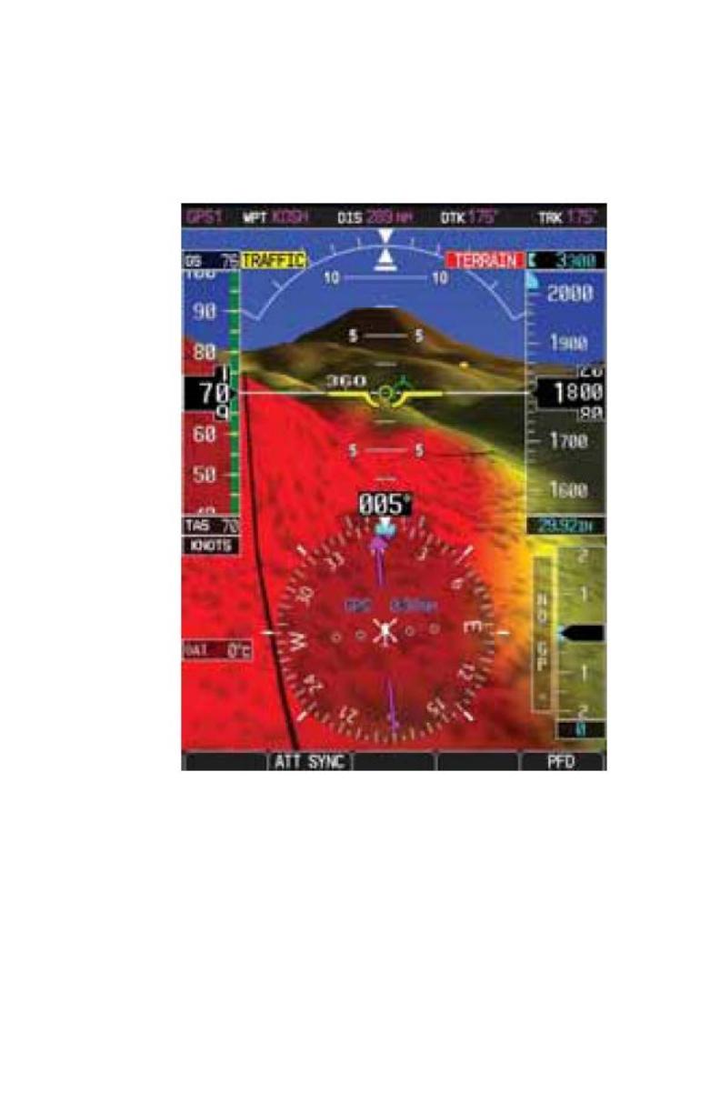
Synthetic Vision
The synthetic vision display of terrain uses several data sources (GPS, terrain
database, attitude information, etc.) in order to accurately display terrain. If any
of these data sources become unreliable or unavailable, the display of synthetic
terrain will automatically revert to the non-SVT PFD display of blue over
brown. Additionally, if during the course of normal operations there is any
discrepancy between actual terrain around the aircraft and terrain shown on the
SVT display, the display of synthetic vision should be manually turned off using
the procedure in section 4.3 of this flight manual supplement.
RFMS, Eurocopter AS350B2, B3 G500H System 190-00792-13 Rev 1
FAA APPROVED Page 19 of 25
Display Dimming
When operating at high Outside Air Temperatures, typically in excess of 20°C,
the GDU 620 display may automatically dim to reduce equipment temperatures.
The display will return to full brightness when operating temperatures are
reduced.
Warnings, Cautions, and Advisory Annunciations
The following tables show the color and significance of the warning, caution,
and advisory messages which may appear on the G500H displays.
NOTE:
The G500H Cockpit Reference Guide and the G500H Pilot’s Guide
contain detailed descriptions of the annunciator system and all
warnings, cautions and advisories.
190-00792-13 Rev 1 RFMS, Eurocopter AS350B2, B3 G500H System
Page 20 of 25 FAA APPROVED
Table 3-1 Warning Annunciations Red
Annunciation
Pilot Action
Cause
ATTITUDE
FAIL
Use visual
references
Display system is not receiving
attitude reference information from
the AHRS; accompanied by the
removal of sky/ground presentation
and a red X over the attitude area
AIRSPEED FAIL
Use Standby
Airspeed
Display system is not receiving
airspeed input from the air data
computer; accompanied by a red X
through the airspeed display.
ALTITUDE
FAIL
Use Standby
Altitude
Display system is not receiving
altitude input from the air data
computer; accompanied by a red X
through the altimeter display.
VERT SPD FAIL
Cross check
instruments
Display system is not
receiving vertical speed
input from the air data
computer; accompanied
by a red X through the
vertical speed display
HDG
Use Standby
Magnetic Compass
or GPS track
information
Display system is not receiving
valid heading from the AHRS;
accompanied by a red X through
the digital heading display.
Red X
Reference the data
source or alternate
equipment
A red X through any display field
indicated that display field is not
receiving data or is corrupted.
TERRAIN
Visually acquire the
terrain and avoid
SVT Terrain has determined that a
nearby terrain poses a collision
hazard.
OBSTACLE
Visually acquire the
obstacle and avoid
SVT Terrain has determined that a
nearby obstacle poses a collision
hazard.
  • Page 1 1
  • Page 2 2
  • Page 3 3
  • Page 4 4
  • Page 5 5
  • Page 6 6
  • Page 7 7
  • Page 8 8
  • Page 9 9
  • Page 10 10
  • Page 11 11
  • Page 12 12
  • Page 13 13
  • Page 14 14
  • Page 15 15
  • Page 16 16
  • Page 17 17
  • Page 18 18
  • Page 19 19
  • Page 20 20
  • Page 21 21
  • Page 22 22
  • Page 23 23
  • Page 24 24
  • Page 25 25

Garmin AS_350B2/B3 Owner's manual

Category
GPS receiver modules
Type
Owner's manual
This manual is also suitable for

Ask a question and I''ll find the answer in the document

Finding information in a document is now easier with AI