Page is loading ...

EXTREME
5000 / & 8000 /
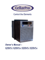
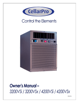
OWNER’S MANUAL
The Coolest Thing In Wine Storage

Page 2
EXti 110111
Copyright © 2011. WhisperKOOL. All rights reserved.
This manual, the product design, and the design concepts are copyrighted by WhisperKOOL, with all rights reserved. Your rights
with regard to the hardware and manual are subject to the restrictions and limitations imposed by the copyright laws of the
United States of America. Under copyright laws, this manual may not be copied, reproduced, translated, transmitted, or reduced
to any printed or electronic medium or to any machine-readable form, for any purpose, in whole or in part, without the written
consent of WhisperKOOL.
Every eort has been made to ensure that the information in this manual is accurate. WhisperKOOL is not responsible for printing
or clerical errors.
WhisperKOOL reserves the right to make corrections or improvements to the information provided and to the related hardware
at any time, without notice.
Vinothèque and WhisperKOOL are registered trademarks, and ECE is a trademark of WhisperKOOL. All rights reserved.
Mention of third-party products is for informational purposes only and constitutes neither an endorsement nor a recommenda-
tion. WhisperKOOL assumes no liability with regard to the performance or use of these products.
11.01.11
We manufacture, test and certify 100% of our wine cooling units in
the USA. By sourcing the best components and closely controlling our
manufacturing processes, we can assure the highest-quality, lowest
defect manufacturing rates in the industry.

Page 1
TABLE OF CONTENTS
Quick Reference Guide
Unit . . . . . . . . . . . . . . . . . . . . . . . . . . . . . . . . . . . . . . . . . . . . . . . . . . . . .
Controller . . . . . . . . . . . . . . . . . . . . . . . . . . . . . . . . . . . . . . . . . . . . . . . .
Fan Speed & Specications . . . . . . . . . . . . . . . . . . . . . . . . . . . . . . .
Introduction . . . . . . . . . . . . . . . . . . . . . . . . . . . . . . . . . . . . . . . . . . . . . . . .
Receiving & Inspecting The Unit . . . . . . . . . . . . . . . . . . . . . . . . . . . .
Quick Start Guide . . . . . . . . . . . . . . . . . . . . . . . . . . . . . . . . . . . . . . . . . . .
Preparing the Wine Cellar . . . . . . . . . . . . . . . . . . . . . . . . . . . . . . . . . . .
Through-the-Wall Installation
Pre-Installation . . . . . . . . . . . . . . . . . . . . . . . . . . . . . . . . . . . . . . . . . . .
Preparing the Installation Location . . . . . . . . . . . . . . . . . . . . . . .
Preparing the System for Installation . . . . . . . . . . . . . . . . . . . . . .
Optional Exterior Grille . . . . . . . . . . . . . . . . . . . . . . . . . . . . . . . . . . .
Installing the Unit . . . . . . . . . . . . . . . . . . . . . . . . . . . . . . . . . . . . . . . .
Ducted Installation
Ducting Overview . . . . . . . . . . . . . . . . . . . . . . . . . . . . . . . . . . . . . . . .
Ducting Congurations . . . . . . . . . . . . . . . . . . . . . . . . . . . . . . . . . .
Installing the Duct Plenums . . . . . . . . . . . . . . . . . . . . . . . . . . . . . .
Remote Controller Installation . . . . . . . . . . . . . . . . . . . . . . . . . . . . .
Drain Line . . . . . . . . . . . . . . . . . . . . . . . . . . . . . . . . . . . . . . . . . . . . . . . . . .
Liquid Measuring Thermostat System . . . . . . . . . . . . . . . . . . . . . .
Multi Speed Control . . . . . . . . . . . . . . . . . . . . . . . . . . . . . . . . . . . . . . . .
System Operation: Standard and Remote . . . . . . . . . . . . . . . . . .
Standard Control Functions . . . . . . . . . . . . . . . . . . . . . . . . . . . . . . . .
Standard Wire Schematic . . . . . . . . . . . . . . . . . . . . . . . . . . . . . . . . . . .
Remote Controller Functions . . . . . . . . . . . . . . . . . . . . . . . . . . . . . . .
Remote Wire Schematic . . . . . . . . . . . . . . . . . . . . . . . . . . . . . . . . . . . . .
Maintenance Schedule . . . . . . . . . . . . . . . . . . . . . . . . . . . . . . . . . . . . .
Troubleshooting Guide . . . . . . . . . . . . . . . . . . . . . . . . . . . . . . . . . . . . .
Technical Assistance & Accessories . . . . . . . . . . . . . . . . . . . . . . . . .
Installation Terms and Conditions . . . . . . . . . . . . . . . . . . . . . . . . . .
2
6
7
8
9
10
11
14
15
16
18
20
21
22
24
25
27
28
29
30
31
34
35
38
39
40
42
44

Page 2
EXti 110111
QUICK REFERENCE GUIDE
5000 - Front / Side View
5000
/ 5000 - Rear / Side View
MADE IN THE USA
Controller
Bottle Probe
Probe Input
Grille w/Filter
Control Panel
(see page 14 for details)
Compressor
Access Panel
Fan Speed Control
Grille w/Filter
Drain Port
Drain Line
Access
Rear Power Option

Page 3
QUICK REFERENCE GUIDE
5000 - Front / Side View
5000
Fully Ducted - Front / Side View
R
MADE IN THE USA
R
Rear
Controller w/Remote Box
Bottle Probe
Grille w/Filter
Control Panel
(see page 14 for details)
Compressor
Access Panel
Compressor
Access Panel
Fan Speed Control
Drain Port
Controller w/Remote Box
Bottle Probe
Return Plenum
Supply Plenum
Control Panel
(see page 14 for details)
Compressor
Access Panel
Fan Speed Control
Exhaust Plenum
Intake Plenum

Page 4
EXti 110111
QUICK REFERENCE GUIDE
8000 - Front / Side View
8000
/ 8000 - Rear / Side View
Controller
Bottle Probe
Probe Input
Grille w/Filter
Control Panel
(see page 14 for details)
Compressor
Access Panel
Fan Speed Control
Grille w/Filter
Drain Port
Rear Power Option

Page 5
QUICK REFERENCE GUIDE
8000 - Front / Side View
8000
Fully Ducted - Front / Side View
Compressor
Access Panel
Controller w/Remote Box
Bottle Probe
Grille w/Filter
Control Panel
(see page 14 for details)
Compressor
Access Panel
Fan Speed Control
Controller w/Remote Box
Bottle Probe
Return Plenum
Supply Plenum
Control Panel
(see page 14 for details)
Compressor
Access Panel
Fan Speed Control
Exhaust Plenum
Intake Plenum

Page 6
EXti 110111
Evaporator and Condenser Fan
•
•
•
•
ALARM
Pre-Chill Display
Control “ON/OFF” Buon
•
Turns the Cooling Unit
“ON/OFF”
1
An Frost
Compressor
Energy Reducon
Hi Bole Temp History & Scroll
Buon
1
Low Bole Temp History & Scroll
Buon
Push to see the min. stored temperature.
In programming mode use to browse the
parameter codes or decrease
the displayed value.
1
Energy Saving
Buon
1
Cellar “Pre-Chill” Buon 3 -5
Push to see the max stored temperature.
In programming mode use to browse the
parameter codes or increase the display
value. Hold for 3 seconds to start fast
freezing cycle.
Set Buon
View Set Point 1
Change Set Point 3-5
SET + Down = CPSM 10-15
Reset Hi & Lo Buon 3 -5
Display and modify set point. In
programming mode it selects a
parameter conrms an opera-
tion. Hold for 3 seconds when
the min or max temperature is
displayed to RESET.
Evaporator and Condenser Fan
Set Buon
•View Set Point
1
•Change Set Point
3-5
•SET + Down = CPSM
3 - 5
•Reset Hi & Lo Buon
3-5
ALARM Pre-Chill Display
Control “ON/OFF” Buon
•
Turns the Cooling Unit
“ON/OFF”
1
An Frost Compressor
Hi Bole Temp History & Scroll
Buon
1
Cellar “Pre-Chill” Buon
3-5
Low Bole Temp History & Scroll
Buon
Push to see the min. stored temperature.
In programming mode use to browse the
parameter codes or decrease
the displayed value.
1
Inacve
Display and modify set point. In
programming mode it selects a
parameter conrms an opera-
tion. Hold for 3 seconds when
the min or max temperature is
displayed to RESET.
Push to see the max stored temperature.
In programming mode use to browse the
parameter codes or increase the display
value. Hold for 3 seconds to start fast
freezing cycle.
QUICK REFERENCE GUIDE
Standard Controller Layout
*If your unit is installed through the wall and does not have a remote keypad you have the Standard Controller*
Remote Controller Layout
*If your unit has a remote keypad then you have the Remote Controller*
Note: The 1 or 3-5 qualies the amount of time in seconds that the button must be pushed to activate the feature.
Refer to page 30 for complete listing of buttons and symbols.
Note: The 1 or 3-5 qualies the amount of time in seconds that the button must be pushed to activate the feature.
Refer to page 34 for complete listing of buttons and symbols.

Page 7
FAN SPEED REFERENCE
UNIT SPECIFICATIONS
Your fan speed selection will depend on the amount of heat that needs to be removed from the cellar and the ap-
plication of the unit (through a wall or fully ducted). Fan speed selection will depend on the cellar size, insulation
factor, door seal and desired wine temperature. When initially installing the unit, set the fan speed to High setting
for a quick chill down. Once the temperature of the cellar reaches the desired temperature, you may be able to select
a lower fan speed to handle the normal load. In the event the temperature outside goes above 90 degrees, (when
exhausting to the outside) you may need to select the higher fan speed.
* To get a feeling for decibels, a food blender at 3ft is 90 dBA, garbage disposal at 3ft is 85 dBA, vacuum cleaner at
10ft is 75 dBA, normal speech at 3ft is 79 dBA, dishwasher in the next room is 55dBA, Quiet night is 35dBA
Fully ducted systems need to be set and stay in the High fan speed position.
Model 5000ti & 5000tiR 8000ti & 8000tiR
Cellar Size 1000 cu. ft. 2000 cu.ft
Dimensions 14.25”W x 15.75”H x 28”D 14.25”W x 22”H x 28”D
Weight 96 lbs 110 lbs
AMPS
(running) 9 10
dBA 51 low 58 med 66 high 57 low 59 med 61 high
Installation Through-the-Wall, Partially Ducted, Fully Ducted
Thermostat Digital Control Display
Temp. Delta
55°F temperature dierential
(maintains proper cellar temperature when exhaust environment does not exceed 110°F)
Outside Venting
Can be done if the outside temperature does not exceed 110°F, the external grille cover is
required.
Ducting Options Unit can be fully ducted.
Warranty 2 year parts and labor / 5 year compressor
Model
5000ti & 5000tiR 8000ti & 8000tiR
Speed Selection
Low Med High Low Med High
Air Flow
(CFM)
147 180 256
274 318 333
Sound
(dBA In Cellar / Out of Cellar)
51/51 58/57 66/65
57/57 59/59 60/61
Cooling Capacity
(BTU/h)
2967 3142 3360
5140 5606 5760

Page 8
EXti 110111
INTRODUCTION
Customer Service
Thank you for purchasing a WhisperKOOL Extreme Series cooling unit. We strive to provide the highest quality prod-
ucts and the best possible customer service. If you have any questions about your WhisperKOOL unit, please call us
at 1(800) 343-9463.
Using the Manual
This User’s Manual is intended to assist in the proper installation and maintenance of the WhisperKOOL Extreme cool-
ing system. In order to ensure the longevity of your cooling unit, the equipment should be installed properly and
have a proper care and maintenance schedule. Please read and review this manual carefully and keep it for future
reference.
What Is the WhisperKOOL Extreme Series Cooling System?
The WhisperKOOL Extreme Series system is a specialized refrigeration unit designed for one purpose only: to main-
tain the optimal temperature and humidity levels conducive to the proper storage and aging of ne wines. It is a
self-contained cooling unit designed to be used as a forced-air through-the-wall unit or as a remote mount unit with
external ductwork connections.
How Does the WhisperKOOL Extreme Series Work?
The WhisperKOOL Extreme Series cooling system is especially designed for the use and application to maintain
optimal conditions for wine storage and aging. The system is fully self-contained and can be installed as a “Through-
The-Wall’ application, or the unit is capable of an even more exible “Ducted” application, which allows the unit to be
placed in an indoor remote site, resulting in a quiet airow. The standard “Through-the-Wall” and ducted units are
temperature controlled via a bottle probe, and the ducted system comes standard with a remote key board that can
be located up to 50 ft from the cooling system (Note: Remote Unit comes standard with a 50 ft bottle probe and 50 ft.
of cable for the remote keypad, additional lengths are optional).
Temperature Setting
The WhisperKOOL Extreme unit can be set at any temperature within the acceptable wine-aging range of 50°F to
67°F. It is designed to cool up to 55°F cooler than the ambient temperature of the space to which it is exhausting.

Page 9
Receiving and Inspecting the Unit
• Lift only at the designated hand hold locations on the shipping container or fully support the unit from un-
derneath. A shipment may include one or more boxes containing accessories.
• Before opening the container, inspect the packaging for any obvious signs of damage or mishandling.
• Write any discrepancy or visual damage on the Bill of Lading before signing.
• Place the box containing the WhisperKOOL unit on a tabletop to prepare it for testing prior to installing.
• Sit upright for 24 hours.
Note: WhisperKOOL Extreme units are manufactured in the USA and tested prior to shipment.
Review the Packing Slip to Verify Contents
• Check the model number to ensure it is correct.
• Check that all factory options ordered are listed.
If any items listed on the packing slip do not match your order information, contact WhisperKOOL Customer Service
immediately.
Check the Box for the following contents:
RECEIVING & INSPECTING THE UNIT
Please leave the WhisperKOOL unit in its original box until you are ready for installation. This will allow you to move
the product safely without damaging it. When you are ready to remove the product from the box, refer to page 12 for
installation instructions.
TIP: Save your box and all packaging materials. They provide the only safe means of transporting/shipping the unit.
5000 / 5000
Single Piece Mounting Bracket
Accessory Kit One:
• WhisperKOOL Extreme Series Owner’s Manual
Accessory Kit Two:
• Power Cord
• Mounting Bracket Insulation Foam 16” (2)
• Mounting Bracket Insulation Foam 17” (2)
• Bottle Temperature Probe (Standard Unit)
Accessory Kit Three:
• 1 ¾ Standard Screws (9)
• ½ Self-Tapping Screws (5)
• ½ x ½ Barbx MNPT Fitting
• Drain Line tube (1)
• Connection “T” (1)
8000 / 8000
Mounting Flanges (4)
Accessory Kit One:
• WhisperKOOL Extreme Series Owner’s Manual
Accessory Kit Two:
• Power Cord
• Mounting Bracket Insulation Foam 16” (2)
• Mounting Bracket Insulation Foam 22” (2)
• Bottle Temperature Probe (Standard Unit)
Accessory Kit Three:
• 1 ¾ Standard Screws (9)
• ½ Self-Tapping Screws (9)
• Drain Line tube (1)
• Tube Clamp (1)
• Connection “T” (1)

Page 10
EXti 110111
QUICK START GUIDE
This guide is meant to serve as a quick reference for installation of the WhisperKOOL unit. The remainder of this
Owner’s Manual will provide more detailed information and instructions.
Upon receiving the WhisperKOOL unit:
1. Inspect the unit before installation. If damage is found, please contact your distributor or WhisperKOOL
Customer Service at 1.800.343.9463 ext 799.
2. The unit should remain in an upright position for 24 hours prior to operation.
3. The WhisperKOOL unit requires a dedicated 115-volt 20-amp circuit. Use a surge protector with the
WhisperKOOL unit. Do not use a GFI (Ground Fault Interrupter) line.
4. For your convenience, the WhisperKOOL unit has two power inlets, one on the side of the unit and the other on the
back. Use the selector switch, located on the right side of the unit, to select the inlet you would like to use.
5. The unit is designed to gently cool down the temperature of the cellar over time by cycling cooler and cooler air
throughout. Test the unit prior to installation. Operate unit for twenty minutes. While the unit is running and
working properly, the air discharged from the front should be 10 - 15°F cooler than the air in the room. This
means that in an environment where the air is 80°F, the unit will discharge air that is 65-70°F.
6. It is REQUIRED to install a drain line to remove condensation from the unit.
7. The WhisperKOOL unit is intended for use in properly designed and constructed wine cellars. Hire a
professional wine storage consultant with a valid contractor’s license to build your wine cellar. Refer to the “How to
Build a Wine Cellar” video available on the WhisperKOOL website at www.whisperkool.com.
8. Install the foam strips along the inside edge of the unit’s flange to assure a proper seal against the wall.
Never try to open the WhisperKOOL unit, repair it yourself, or use a service company
without WhisperKOOL’s authorization. This will void your warranty.
If you encounter a problem with your WhisperKOOL unit, please refer to the Troubleshooting Guide on page 36.
If you have any further questions, concerns, or need assistance, please contact WhisperKOOL Customer Service at
1.800.343.9463 ext. 799. Please be sure all testing has been completed prior to contacting Customer Service. Please
have your results ready for your representative.

Page 11
The performance and life of your WhisperKOOL unit is contingent upon the
steps you take in preparing the wine cellar.
Note: Improperly preparing your enclosure or incorrectly installing your WhisperKOOL
unit may cause unit failure, leaking of condensation, and other negative side eects.
IT IS HIGHLY RECOMMENDED THAT YOU OBTAIN THE ASSISTANCE
OF A WINE STORAGE PROFESSIONAL.
Wine storage professionals work with licensed contractors, refrigeration technicians, and racking companies to build
well-insulated, beautiful, and protective wine cellars. WhisperKOOL has put together some useful tips to assist in the
installation process. Our recommendations are meant to act as a guide in the process of building a proper enclosure.
Your intended location may have specic needs that we do not address.
How to Build a Wine Cellar Instructional Video
WhisperKOOL has a construction tutorial available on line at our website: www.whisperkool.com. This tutorial will walk
you through the steps of constructing a properly built wine cellar and the installation of our WhisperKOOL product line.
Wall & Ceiling Framing
Build wine cellar walls using standard 2x4 or 2x6 construction methods and ceiling joists following the guidelines of
local and state codes in your area. As a general rule, the thicker the walls and the higher the insulation value in your
cellar, the better it will be at maintaining a consistent temperature.
Insulation
Insulation is REQUIRED with the use of the WhisperKOOL product. Standard berglass or rigid foam insulation is nor-
mally used in cellar construction or, in some cases, “blown-in” insulation is used. It is very important that all walls and
ceilings are insulated to keep the cellar temperature as consistent as possible during the summer and winter months.
The R-value, or quality of insulation, is determined by the rate at which heat passes through the insulation. The
higher the R-value, the more resistant the insulation is to conducting heat. Using higher R-values in insulation will
lower your operating costs and unit run time. (R-13 minimum, R-19 recommended, R-30 for ceiling and exterior walls.)
Vapor Barrier
A vapor barrier is REQUIRED to prevent the intrusion of water vapor so that the cellar can be kept at the correct
temperature and humidity. 6 mm plastic sheeting (recommended) should be applied to the warm side of the cellar
walls. The vapor barrier must also be applied to the outside walls and ceiling. If it is impossible to reach the outside,
then the plastic must be applied from within the cellar. The most common method is to wrap the entire interior, leav-
ing the plastic loose in the stud cavity so the insulation can be placed between each stud. All of the walls and ceiling
must be wrapped in plastic for a complete vapor barrier.
In areas of high humidity, such as Southern and Gulf States, the vapor barrier will prevent inltration of warm moist
air. The moist air can cause mold to form, and standing water in drain pans promote microbial and fungal growth that
cause unpleasant odors and indoor air quality problems. If mold is found, remove it immediately and sanitize that
portion of the unit.
PREPARING THE WINE CELLAR

Page 12
EXti 110111
Unobstructed Airow
Unobstructed airflow too and from the unit is critical for the unit’s overall performance and life-span. A mini-
mum three-foot clearance (five foot is ideal) area is crucial. The air the fans blow needs to circulate and either dissi-
pate or absorb heat from the space, the more air to exchange the more efficient the system will operate.
Note: Avoid attempting to camouflage the unit. This will restrict airflow and thus the unit’s ability to work efficiently.
Mounting the Unit
The unit must be mounted within 18“ of the top of the room in order to achieve sucient cooling. As the room cools
down, the warm air will rise to the ceiling. Mounting the WhisperKOOL high in the room will create a consistently
cool environment by capturing the warm air and replacing it with cool air. Mounting the unit low in the room will
result in a temperature variation in the room due to the unit’s inability to draw warm air from the ceiling of the cellar
to the unit itself, and cold air settling to the oor.
Door and Door Seal
An exterior grade (1 3/4”) door must be installed as a cellar
door. It is very important that weather stripping is at-
tached to all 4 sides of the doorjamb. A bottom “sweep” or
threshold is also required. The door must have a very good
seal to keep the cool cellar air from escaping out of the
cellar. One of the most common problems with cooling
units running continually is due to the door not sealing
properly. In cases where glass doors are used and the
room size is close to the recommended unit size, the
next larger size WhisperKOOL should be used. This will
compensate for the insulation loss due to the lower insu-
lating rating of glass.
HIGH
MED
LOW
Wine Cellar
Exhaust Area
Keep Clear
Exhaust Fan/Vent
(optional)
Air Intake
(optional)

Page 13
Ambient Temperature Factor
The cooling system has the ability to cool a wine cellar eciently to 55°F as long as the ambient temperature of the
area that it is exhausting to does not exceed 110°F. Therefore, you want to exhaust the unit in a room which will not
exceed 110°F. Otherwise the unit will not have the capacity to keep the wine at a desirable 55°F.
Back - Exhaust Room
Exhaust Fan
Air Intake Cellar Wall
110ºF 55ºF
Front
-
Wine Cellar
WhisperKOOL
(side view)
Ventilation
The necessity of dissipating heat away from the unit is critical to the unit’s performance and cannot be overstated. As
the unit operates and cools, a greater amount of heat is generated on the exhaust side of the unit. Adequate ventila-
tion is required in order to dissipate heat away from the unit. If ventilation is inadequate, the exhaust will heat up the
area or room and adversely aect the unit’s ability to cool. In some cases, it may be advisable to install a vent fan to
dissipate heat within the exhaust area on the backside of the unit. However, you must have a fresh air inlet as well. If
your unit requires ducting, please contact WhisperKOOL to obtain a specially designed ducting plenums for the unit.
Using any other ducting system will void the warranty.
Note: If you are unsure about having adequate ventilation in your install location, please
contact us to assess your specic installation at [email protected] or 1.800.343.9463.
Warning, allowing your system to operate in high ambient temperatures for extended
periods of time will greatly decrease the life of your system and void your warranty.

Page 14
EXti 110111
TEST THE UNIT PRIOR TO INSTALLATION
To prepare it for testing before installation in wall:
• Unit needs to be in the upright position for 24 hours before starting.
• Remove unit from box
• Place unit on tabletop
• Plug in unit to electrical outlet
• Plug in bottle probe
• Turn on to test (Should be 10°F- 15°F across coils) approximately 20-30 minutes
• Turn o after test
• Remove bottle sensor
Electrical Needs
The WhisperKOOL Extreme System requires a dedicated 115-volt 20-amp circuit. The unit draws a large amount
of amps at initial start up. By designating a dedicated circuit breaker, you will guarantee the unit has enough power
to run eectively. Contact an electrician for assistance with the installation of this dedicated electrical circuit:
• Match the electrical outlet to the plug provided on the WhisperKOOL unit.
• Provide a dedicated circuit and wiring for the unit.
• Provide a weatherproof plug for units connected outside.
Plug your WhisperKOOL unit into a surge protector or power conditioner. As with any sensitive electrical equipment,
the WhisperKOOL electrical equipment may be damaged by power surges and spikes. Power surges and spikes are
not covered under warranty.
WE RECOMMEND THAT YOU DO NOT USE A GROUND FAULT INTERRUPTER (GFI) WITH THIS PRODUCT.
Electrical Inlets
The unit is equipped with two power inlets: One is located on the right side of the unit; (inside the cellar) the other is
located on the rear of the unit (outside of the cellar). Use the selector switch located on the right side of the unit to
select which power inlet you would like to utilize. (Meaning if you would like to plug the unit into a socket outside
of the cellar, set the selector switch to rear; if you would like to plug the unit into a socket inside of the cellar, set the
selector switch to the front position. When placed in either position power can only enter the unit utilizing the power
inlet you’ve selected.)
In case the unit should lose power, check the home/main circuit breaker. If the unit does not respond properly, refer
to the Troubleshooting section on page 39.
PRE-INSTALLATION
FRONT
REAR
Power Inlet
Front / Rear
Power Switch

Page 15
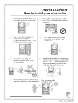
Minimum Tools Needed
Locate the desired installation location (no lower than 18” inches from the
ceiling). Using a stud nder, locate the studs on either side of the center
point, and mark them with vertical lines.
Using a level and a pencil, mark a horizontal line on the wall between the two
studs, no less than 1 1/2” and no more than 18” from the ceiling.
Using a ruler or measuring tape, measure 16” down (5000ti/tiR) or 22.25”
down (8000 ti/tiR), and mark another horizontal line parallel to the rst one.
Using a saw, cut along the uppermost horizontal line until your saw reaches
the stud. Turn the saw around, inserting it into the cut you have just made,
and cut toward the opposite stud so that you have a clean horizontal cut be-
tween the two studs. Be careful not to cut into the studs themselves.
Now make the second horizontal cut from stud to stud on the line 16” below
the rst cut.
Once the horizontal lines have been cut, make vertical cuts using the inside
edge of the studs as a guide. Once you have made both vertical cuts, you
should have a rectangular hole in the sheetrock. Now you have to make the
same hole on the other side of the wall. Since you already have one hole,
this is an easy process. Using a nail, mark all four corners of the rst hole by
making nail holes through the sheetrock. Then on the other side of the wall,
connect the holes with a pencil mark and cut.
Sheetrock alone cannot support the weight of a 96-pound cooling system.
Therefore, it is necessary to frame the hole that you have just cut with upper
and lower supports. These supports also provide solid material for the mount-
ing bracket screws.
Using two 2x4s at 14.5” in length and eight 6d nails, secure the upper and
lower supports to the right and left studs, just inside the sheetrock. Make sure
that the internal height remains at 16” (5000ti/tiR) or 22.25” (8000 ti/tiR) so
that the WhisperKOOL system will t snugly through the framed cut-out.
Hammer SawScrewdriver
Level
PREPARING THE INSTALLATION LOCATION
Through-the-Wall

Page 16
EXti 110111
PREPARING THE SYSTEM FOR INSTALLATION
5000 / 5000
Applying Insulation Tape
Locate the (4) precut pieces of black foam tape included with the system, two larger
pieces and two smaller pieces. To apply, simply peel back the white-paper adhesive cov-
ering and place on the mounting bracket. The large pieces are applied to the top and
bottom while the smaller pieces are for the sides. This foam creates a tight seal between
the bracket and the wall.
Single Piece Mounting Bracket
The 5000ti/tiR utilizes a single piece mounting bracket, this sturdy bracket frames the in-
stallation location and secures the unit to the wall. WhisperKOOL has also designed the
bracket to hold the system at a 2º degree angle, this helps project the air into the space
and aids in condensation drainage.
Mounting Bracket Installation
Select your desired bracket mounting location (see diagram below), this location determines the depth of the instal-
lation. For example, position #1 keeps most of the system out of the cellar while position #4 makes the back of the
system near ush on the exterior wall. Slide bracket onto unit, pay special attention to the TOP label on the bracket
and the anges for mounting to the unit are towards the back. Use the (4) supplied 1/2” self tapping screws to fasten
the bracket to the unit. It is imperative to not use self tapping screws longer than 1/2” in length.
If you are installing through an exterior wall, please review page 18 for
specic instructions on exterior grill installation.
7.5-8.5” inches In Cellar
#
1
#
2
#
3
#
4
11.5-12.5” inches In Cellar
15.5-16.5” inches In Cellar
19.5-20.5” inches In Cellar
5” inch thick wall
(wall thickness may vary)
Mounting Bracket
Wine Cellar Exhaust Area

Page 17
PREPARING THE SYSTEM FOR INSTALLATION
8000 / 8000
Applying Insulation Tape
Locate the (4) precut pieces of black foam tape included with the system, two larger
pieces and two smaller pieces. To apply, simply peel back the white-paper adhesive
covering and place on the mounting ange. The small pieces are applied to the top
and bottom while the larger pieces are for the sides. This foam creates a tight seal
between the ange and the wall.
Mounting Flanges
Your system utilizes mounting anges (4) to frame the installation location and secure
the unit to the wall.
Mounting Flange Installation
Select your desired ange mounting location (see diagram below), this location deter-
mines the depth of the installation. For example, position #1 keeps most of the system out of the
cellar while position #3 makes the back of the system near ush on the exterior wall. Use the (8) supplied 1/2” self tap-
ping screws to fasten the anges to the unit. It is imperative to not use self tapping screws longer than 1/2” in length.
If you are installing through an exterior wall, please review page 19 for
specic instructions on exterior grill installation.
#
1
#
2
#
3
11.5-12.5” inches In Cellar
15.5-16.5” inches In Cellar
19.5-20.5” inches In Cellar
5” inch thick wall
(wall thickness may vary)
Mounting Flange
Wine Cellar Exhaust Area

Page 18
EXti 110111
Exterior Grille Installation
The exterior grille is required on all installations where the exhaust side of the unit is exposed to the outside of the
dwelling (i.e. rain and weather).
Non-Flush Installation
Install the system according to the standard through-the-wall procedure. After the system is installed, place the exte-
rior grille over the exhaust side ler grille and line up the screw holes on the top, bottom, and sides. Use the supplied
(8) self tapping screws to fasten the grille to the unit.
Flush Installation
This installation is slightly dierent because you are utilizing the same holes for both the mounting bracket and exte-
rior grille.
1. Slide the mounting bracket onto the unit followed by the exterior grille, bring the two pieces together by slid-
ing the exterior grille over the mounting bracket side anges.
2. Align the (2) top screw holes of the exterior grill with the top screw locations on the system, use the supplied
self tapping screws to fasten the grille.
3. Repeat step 2 on the bottom of the system.
4. You will notice the side holes do not line up, use the supplied self tapping screws to fasten the grille and
bracket to the system ensuring the bracket stays perpendicular/square.
5. Continue through-the-wall installation.
It is required to use self tapping screws provided. Do not drill screws into unit.
OPTIONAL EXTERIOR GRILLE
5000 / 5000
Non-Flush Installation
Flush Installation
/