Henny Penny OFG-341 User manual

Category
Deep fryers
Type
User manual
Model OFE/OFG/OEA/OGA-341, 342
2-1. INTRODUCTION This section provides the installation instructions for the
Henny Penny open fryer.
Installation of the unit should be preformed only by a
qualified service technician.
Do not puncture the unit with any objects such as drills
or screws as component damage or electrical shock
could result.
2-2. UNPACKING
The Henny Penny open fryer has been tested, inspected,
and expertly packed to ensure arrival at its destination in
the best possible condition. The unit is banded to a wooden
skid and then packed inside a heavy cardboard carton with
sufficient padding to withstand normal shipping treatment.
Any shipping damage should be noted in the presence
of the delivery agent and signed prior to his or her
departure.
1. Carefully cut bands from cardboard carton.
2. Lift carton from fryer.
3. Cut and remove the metal bands holding the fryer to the
pallet.
4. Remove the fryer from the pallet.
Take care when moving the fryer to prevent
personal injury. Single-well fryers weigh 348lbs.
(158 kg) and 2-well fryers weigh 700 lbs. (318 kg).
2-1 903
SECTION 2. INSTALLATION
Model OFE/OFG/OEA/OGA-341, 342
2-3. SELECTING THE Proper location of the open fryer is very important for
LOCATION
operation, speed, and convenience. Locate the open fryer to
allow clearances for servicing and proper operation. Choose
a location which provides easy loading and unloading
without interfering with the final assembly of food orders.
Operators have found that frying from raw to finish, and
holding the product in warmers provides fast continuous
service. Keep in mind the best efficiency is obtained by
a straight line operation, i.e. raw in one side and finished out
the other side. Order assembly can be moved away with only
a slight loss of efficiency.
To avoid fire, install the open fryer with minimum clearance
from all combustible and noncombustible materials, 0
inches (0.0 cm) from the side and 6 inches (15.24 cm) from
the back. If installed properly, the open fryer is designed for
operation on combustible floors and adjacent to combustible
walls.
To prevent severe burns from splashing hot
shortening, position and install fryer to prevent
tipping or movement. Restraining ties may be used
for stabilization.
2-4. LEVELING THE OPEN
For proper operation, level the open fryer from side to side
FRYER
and front to back. Using a level placed on the flat areas
around the frypot collar, on the middle well, adjust fryer
accordingly.
2-5. VENTILATION OF FRYER
Locate the open fryer with provision for venting into an
adequate exhaust hood or ventilation system. This is
essential to permit efficient removal of the steam exhaust and
frying odors. Take special precautions in designing an
exhaust canopy to avoid interference with the operation of
the open fryer. We recommend you consult a local
ventilation or heating company to help in designing an
adequate system.
Ventilation must conform to local, state, and national
codes. Consult your local fire department or building
authorities.
603 2-2
Model OFE/OFG/OEA/OGA-341, 342
2-5. VENTILATION OF FRYER
(Continued)
When installing the gas fry station do not attach an
extension to the gas flue exhaust stack. This may impair
proper operation of the burner, causing malfunctions
and possible negative back draft.
2-6. GAS SUPPLY The gas open fryer is factory available for either natural or
propane gas. Check the data plate inside the front door of the
cabinet to determine the proper gas supply requirements. The
minimum supply for natural gas is 7 inches water column, and 10
for propane.
Do not attempt to use any gas other than that specified
on the data plate. Incorrect gas supply could cause a fire
or explosion resulting in severe injuries and/or property
damage.
Refer to the illustration on the following page for the
recommended hookup of the Open Fryer to the main gas line
supply.
To avoid possible serious personal injury:
Installation must conform with local, state, and national
codes.
• Installation must conform with American National
Standard Z223.1-Latest Edition National Fuel Gas Code
and the local municipal building codes. In Canada,
installation must be in accordance with Standards
CAN/CSA B 149.1 and 149.2, & Installation Codes - Gas
Burning Appliances and local codes. In Australia, in
accordance with Australian Gas Authority rules AG601-
2000, section AS5601.
• Isolate the fryer from the gas supply piping system by
closing its individual manual shut off valve during any
pressure testing of the gas supply piping system at test
pressures equal to or less than 1/2 PSIG (3.45 KPA)
(34.47 mbar).
• The appliance and its individual shutoff valve must be
disconnected from the gas supply system during any
pressure testing in excess or ½ psi (3.45 KPA).
2-3 903
Model OFE/OFG/OEA/OGA-341, 342
603 2-4
Model OFE/OFG/OEA/OGA-341, 342
2-6. GAS SUPPLY A standard one inch, black steel pipe and malleable fit-
(Continued)
tings should be used for gas service connections.
Do not use cast iron fittings.
Although 1 inch (2.54 cm) sized pipe is recommend for 2
wells and 3/4 inch (1.9 cm) sized pipe is recommended
for single wells, use adequate sized pipe and install
properly, to provide a supply of gas sufficient to meet
the maximum demand without undue loss of pressure
between the meter and the open fryer. The pressure loss
in the piping system should not exceed 0.3-inch water
column (.747 mbar).
Do not adjust the vacuum pressure switch. It is factory
set for the most efficiency.
Provisions should be made for moving the open fryer for
cleaning and servicing. This may be accomplished by:
1. Installing a manual gas shut off valve and a disconnect
union, or
2. Installing a heavy-duty design CSA certified
connector. In order to be able to service this appliance,
which is provided with casters, a connector complying
with ANSI Z21.69 or CAN 1-6.l0m88 and a
quick-disconnect device, complying with ANSI Z21.41
or CAN 1-6.9m70,
must be installed. It must also be
installed with restraining means to guard against
transmission of strain to the connector as specified in the
appliance manufacturers instruction.
3. Refer to the cable restraint instructions, on preceding page,
on how and where to attach the restraining devices to
the wall and fryer.
The cable restraint limits the distance the open fryer
can be pulled from the wall. For cleaning and
servicing the unit, the cable must be unsnapped from
the open fryer and the flexible gas line disconnected.
This allows better access to all sides of the open
fryer. The gas line and cable restraint must
be
reconnected once the cleaning or servicing is
complete.
2-5 1209
Model OFE/OFG/OEA/OGA-341, 342
2-7. GAS LEAK TEST
Prior to turning the gas supply on, be sure the gas valve
knob on the gas control valve is in the OFF position.
Upon initial installation, and after moving the unit, the piping
and fittings should be checked for gas leaks. A simple
checking method is to turn on the gas and brush all
connections with a soap solution. If bubbles occur, it
indicates escaping gas.
To avoid fire or explosion, never use a lighted match or
open flame to test for gas leaks. ignited gas could result
in severe personal injury and/or property damage.
2-8. PRESSURE REGULATOR The gas pressure regulator on the automatic gas valve is
factory set as follows:
Natural: 3.5 inches water column (8.7 mbar).
Propane 10.0 inches water column (24.9 mbar).
The gas pressure regulator has been set by Henny
Penny and is not to be adjusted by the user.
2-9. ELECTRICAL
120 V, 60 Hz., 12 A, 1 PH
REQUIREMENTS
230 V, 50 Hz., 6.2 A, 1 PH
OFG/OGA-340 SERIES
The 120 V gas fry station requires a 3 wire grounded
(Earthed) service and is supplied with a grounded cord and
plug. Any 230-volt plug used on the 230-volt unit must
conform to all local, state, and national codes.
To avoid electrical shock, this appliance must be
equipped with an external circuit breaker which will
disconnect all ungrounded (unearthed) conductors.
The main power switch on this appliance does not
disconnect all line conductors.
903 2-6
Model OFE/OFG/OEA/OGA-341, 342
2-9. ELECTRICAL
REQUIREMENTS
OFG/OGA-340 SERIES
(Continued)
To avoid electrical shock, do not disconnect the ground
(earth) plug.
This fryer must be adequately and safely
grounded. Refer to local electrical codes for correct
grounding (Earthing) proceduresor in absence of local
codes, with the National Electrical Code, ANSI/NFPA
No. 70 Latest Edition. Canadian models are supplied
with a terminal box, suitable for conduit connection. In
Canada, all electrical connections are to be made in
accordance with CSA C221, Canadian Electrical
Code Part 1, and/or local codes.
2-10. ELECTRICAL Refer to the table below for supply wiring and fusing.
REQUIREMENTS
(Per Well)
OFE/OEA-340 SERIES Volts Phase Kw Amps
208 3 22.0 61
240 3 22.0 53
380-415 3N+G 22.0 32.5
To avoid electrical shock, this appliance must be
equipped with an external circuit breaker which will
disconnect all ungrounded (unearthed) conductors.
The main power switch on this appliance does not
disconnect all line conductors.
To avoid electrical shock, this fryer must
be
adequately and safely grounded (earthed). Refer to
local electrical codes for correct grounding (earthing)
procedures or in absence of local codes, with The
National Electrical Code, ANSI/NFPA No. 70-(the
current edition). In Canada, all electrical connections are
to be made in accordance with CSA C22.1, Canadian
Electrical Code Part 1, and/or local codes.
CE units require a minimum wire size of 6mm to be wired to the
terminal block. If a flexible power cord is used, it must be
HO7RN type.
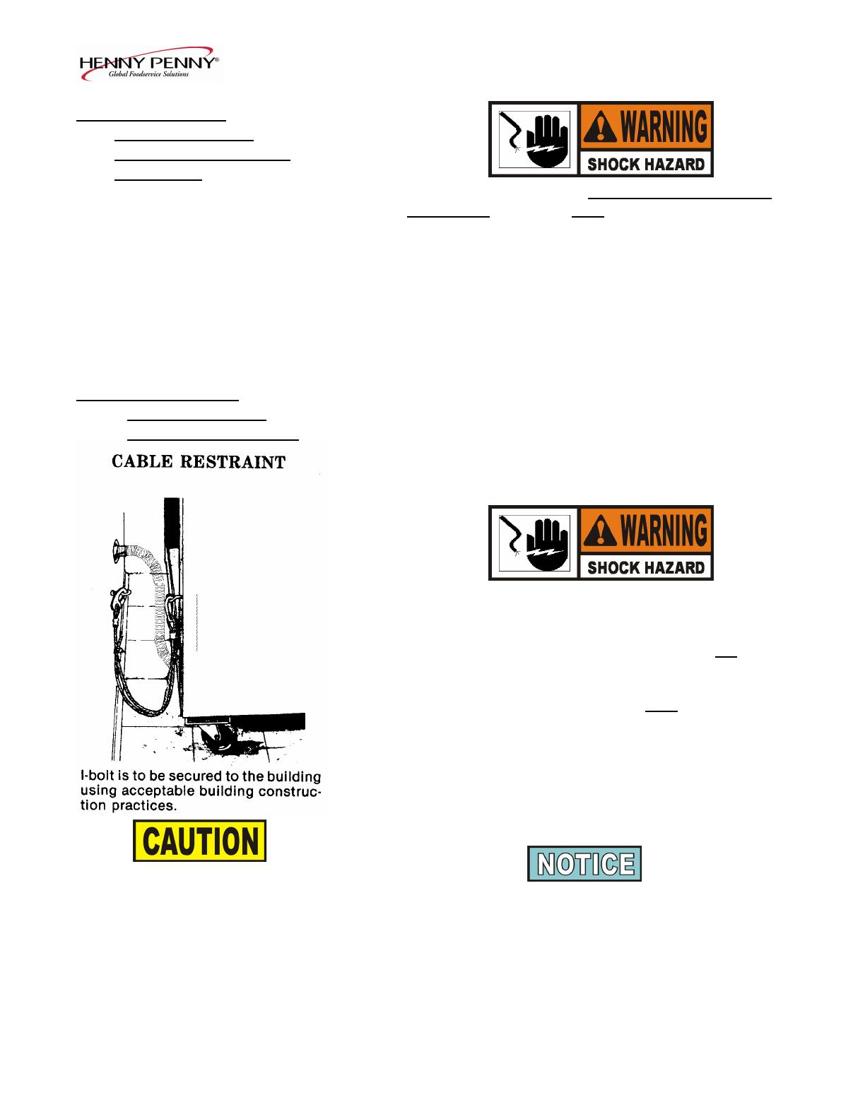
Permanently connected electric fryers with casters must be
installed with flexible conduit and a cable restraint, when installed
in the United States. See illustration at left. Holes are available in
the rear fryer frame for securing the cable restraint to the fryer.
The cable restraint does not prevent the fryer from tipping.
2-7 705
DRYWALL CONSTRUCTION
Secure I-bolt to a building stud. Do
not attach to drywall only. Preferred
installation is approximately six
inches to either side of service.
Cable restraint must be at least six
inches shorter than flexible conduit.
Model OFE/OFG/OEA/OGA-341, 342
2-11 ADDITIONAL CE
ELECTRICAL STATEMENTS
The supply power cords shall be oil-resistant,
sheathed flexible cable, no lighter than ordinary
polychloroprene or other equivalent synthetic
elastomer-sheathed cord.
It is recommended that a 30 mA rated protective
device such as a residual current circuit breaker
(RCCB), or ground fault circuit interrupter
(GFCI), be used on the fryer circuit.
Equipotential Ground Symbol =
(FOR EQUIPMENT WITH CE MARK ONLY!)
To prevent electric shock hazard this appliance
must be bonded to other appliances or touchable
metal surfaces in close proximity to this
appliance with an equipotential bonding
conductor. This appliance is equipped with an
equipotential lug for this purpose. The
equipotential lug is marked with the following
symbol
.
1107 2-8
  • Page 1 1
  • Page 2 2
  • Page 3 3
  • Page 4 4
  • Page 5 5
  • Page 6 6
  • Page 7 7
  • Page 8 8

Henny Penny OFG-341 User manual

Category
Deep fryers
Type
User manual

Ask a question and I''ll find the answer in the document

Finding information in a document is now easier with AI