IS-N50D 0829 EDP#1910640 © Watts, 2008
USA: 815 Chestnut St., No. Andover, MA 01845-6098; www.watts.com
Canada: 5435 North Service Rd., Burlington, ONT. L7L 5H7; www.wattscanada.ca
Water Safety & Flow Control Products
Limited Warranty: Watts Regulator Co. (the “Company”) warrants each product to be free from defects in material and workmanship under normal usage for a period of one year from the date of
original shipment. In the event of such defects within the warranty period, the Company will, at its option, replace or recondition the product without charge.
THE WARRANTY SET FORTH HEREIN IS GIVEN EXPRESSLY AND IS THE ONLY WARRANTY GIVEN BY THE COMPANY WITH RESPECT TO THE PRODUCT. THE COMPANY MAKES NO OTHER
WARRANTIES, EXPRESS OR IMPLIED. THE COMPANY HEREBY SPECIFICALLY DISCLAIMS ALL OTHER WARRANTIES, EXPRESS OR IMPLIED, INCLUDING BUT NOT LIMITED TO THE IMPLIED
WARRANTIES OF MERCHANTABILITY AND FITNESS FOR A PARTICULAR PURPOSE.
The remedy described in the first paragraph of this warranty shall constitute the sole and exclusive remedy for breach of warranty, and the Company shall not be responsible for any incidental, special
or consequential damages, including without limitation, lost profits or the cost of repairing or replacing other property which is damaged if this product does not work properly, other costs resulting
from labor charges, delays, vandalism, negligence, fouling caused by foreign material, damage from adverse water conditions, chemical, or any other circumstances over which the Company has no
control. This warranty shall be invalidated by any abuse, misuse, misapplication, improper installation or improper maintenance or alteration of the product.
Some States do not allow limitations on how long an implied warranty lasts, and some States do not allow the exclusion or limitation of incidental or consequential damages. Therefore the above
limitations may not apply to you. This Limited Warranty gives you specific legal rights, and you may have other rights that vary from State to State. You should consult applicable state laws to
determine your rights. SO FAR AS IS CONSISTENT WITH APPLICABLE STATE LAW, ANY IMPLIED WARRANTIES THAT MAY NOT BE DISCLAIMED, INCLUDING THE IMPLIED WARRANTIES OF
MERCHANTABILITY AND FITNESS FOR A PARTICULAR PURPOSE, ARE LIMITED IN DURATION TO ONE YEAR FROM THE DATE OF ORIGINAL SHIPMENT.
For loads in excess of ratings or when a 3-phase burner motor is
used, use either switch as pilot to operate a relay or magnetic start-
er as shown under "Pilot Duty" above for burner switch. Incoming
leads must be suitable for temperature rise of 90°C (194°F).
Motor Duty
AC
1
⁄2 H.P. 1 Phase 110-120 volts
1 H.P. 1 Phase 220-240 volts
Pilot Duty
AC 15 Amps. 120, 240 volts
DC
1
⁄2 Amps. 120 volts
Motor Duty
AC
1
⁄2 H.P. 1 Phase 110-120 volts
1 H.P. 1 Phase 220-240 volts
Pilot Duty
AC 15 Amps. 120, 240 volts
DC
1
⁄2 Amps. 120 volts
Alarm Circuit
AC 15 Amps. 120, 240 volts
DC
1
⁄2 Amps. 120 volts
WARNING: Do not connect to an electrical load in excess of the
rated capacity of the switch. Switch cuts off burner or stoker when
water line drops approximately
3
⁄8" below center line. Switch alarm
circuit when used is closed just before burner cuts off.
CAUTION: "This switch mechanism is factory set for optimum
performance, alteration may cause the valve to malfunction and
will invalidate the warranty."
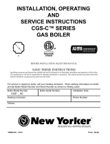
Wiring Diagrams
When Used For PILOT DUTY
TOP
Burner Switch
Closed Circuit
LINE
LINE (Burner)
RELAY
Norm
Open
Norm
Closed
Common
(Dual Switch) When Used for
Burner Switch and Accessory Circuits
TOP
LINE
HI or LO
Voltage
( )
HI or LO Voltage
Alarm Feed Valve
or Pump Starter
Burner
Load
Service Switch
Closed Circuit
Burner Switch
Closed Circuit
LINE
Norm
Open
Norm
Open
Norm
Closed
Norm
Closed
CommonCommon
(Single Switch)
When Used for Burner Switch
TOP
Burner
Load
Burner Switch
Closed Circuit
LINE
Common
Norm
Open
Norm
Closed
When Used For PILOT DUTY
TOP
LINE
HI or LO
Voltage
( )
HI or LO Voltage
Alarm Feed Valve
or Pump Starter
Service Switch
Closed Circuit
Burner Switch
Closed Circuit
LINE
LINE (Burner)
RELAY
Common Common
Norm
Open
Norm
Open
Norm
Closed
Norm
Closed