Page is loading ...

Gas-Electric Package
Unit
Cooling and Heating
Installation Instructions
MODELS
PGC(24-60)B and
PGB58B
May 1998 (2) 11073904
Amana
Fayetteville, TN 37334
As a professional installer you have an obligation to
know the product better than the customer. This in-
cludes all safety precautions and related items.
Prior to actual installation, thoroughly familiarize your-
self with this Instruction Manual. Pay special atten-
tion to all safety warnings. Often during installation or
repair it is possible to place yourself in a position which
is more hazardous than when the unit is in operation.
Remember, it is your responsibility to install the
product safely and to know it well enough to be able
to instruct a customer in its safe use.
Safety is a matter of common sense...a matter of think-
ing before acting. Most dealers have a list of specific
good safety practices...follow them.
The precautions listed in this Installation Manual
should not supersede existing practices but should
be considered as supplemental information.
ATTENTION INSTALLING PERSONNEL
RECOGNIZE THIS SYMBOL AS A SAFETY PRECAUTION
Affix These Installation Instructions Adjacent To The Appliance.
Table of Contents
I. Unit Specifications ........................................ 2
II. Safety Information ......................................... 6
III. General Information ...................................... 7
IV. Rigging and Handling ................................... 9
V. Gas Piping .................................................... 10
Vl. Electrical Wiring .......................................... 12
Vll. Circulating Air and Filters .......................... 13
VIII. Flue Vent....................................................... 16
IX. Condensate Drain........................................ 16
X. Heating Sequence of Operations............... 18
XI. Cooling Sequence of Operations .............. 18
XIl. Startup and Adjustment.............................. 18
XIII. Maintenance................................................. 24
XIV. Accessories and Functional Parts ............ 26
XV. Typical Cooling Performance Data ............ 27
XVI. Wiring Diagram ............................................ 29
A higher standard of comfort
Heating
¡
Air Conditioning
®

2
I. Unit Specifications
MODEL PGC24B0452A PGC24B0702A PGC30B0702A PGC36B0702A PGC36B0902A
Cooling Capacity Btuh 24,000 24,000 30,000 36,000 36,000
SEER 12.50 12.50 12.30 12.00 12.00
Heating
Input Btuh 45,000 70,000 70,000 70,000 90,000
Output Btuh 35,000 55,000 55,000 55,000 70,000
AFUE 80.9 80.1 80.1 80.1 80.4
Temperature Rise °F 20-50 30-60 30-60 30-60 40-70
Number of Burners 2 3 3 3 4
Compressor
R.L. Amps 12.9 12.9 15 20 20
L.R. Amps 62.5 62.5 76 90.5 90.5
Condenser Coil
Face Area (sq. ft.) 12.3 12.3 12.3 14 14
Rows Deep 1 1/2 1 1/2 2 2 2
Fins/Inch 13 13 13 13 13
Condenser Fan
Diameter (in.) 20 20 20 20 20
CFM 2670 2670 2700 3060 3060
Condenser Fan Motor
Horsepower 1/8 1/8 1/4 1/4 1/4
R.L. Amps 0.8 0.8 1.2 1.5 1.5
L.R. Amps 1.5 1.5 3 3.4 3.4
Blower Motor
Horsepower 0.5 0.5 0.5 0.5 0.5
R.L. Amps 4.3 4.3 4.3 4.3 4.3
L.R. Amps Protected by redundant electronic control circuits
Blower Wheel Dia. x Width (in.) 10x7 10x7 10x7 10x7 10x7
Rated CFM, Cooling 850 850 1100 1300 1300
Max. External 0.8" wc 0.8" wc 0.8" wc 0.8" wc 0.8" wc
Combustion Blower
Diameter x Width (in.) 4 x 1.25 4 x 1.25 4 x 1.25 4 x 1.25 4 x 1.25
No. 11111
Condenser Blower Motor
H.P. 0.03125 0.03125 0.03125 0.03125 0.03125
F.L. Amps. 0.5 0.5 0.5 0.5 0.5
Press. Switch Setting (" W.C.) -0.65 -0.65 -0.65 -0.65 -0.65
Ignition - Lockout Timing (sec.) 4 4 4 4 4
Flame Sense Current (microamps)
Minimum 11111
Maximum 66666
Evaporator Coil
Face Area (Sq. Ft.) 4 4 4 4 4
Rows Deep 22244
Fins/Inch 16 16 16 12 12
External Filter Size (Sq. Ft.) 3.6 3.6 3.6 3.6 3.6
Drain Line Size (in.) 3/4 3/4 3/4 3/4 3/4
Expansion Device (Cooling) Capillary Capillary Capillary Capillary Capillary
Refrigerant Charge Refer to unit name plate for correct charge
Power Supply** 208/230-60-1 208/230-60-1 208/230-60-1 208/230-60-1 208/230-60-1
Min. Circuit Ampacity 21.3 21.3 24.3 30.8 30.8
Max. Overcurrent Device 30 30 35 45 45
Electrical Entrance Size
Power Supply 1 1/4", 1 1/2", 2" 1 1/4", 1 1/2", 2" 1 1/4", 1 1/2", 2" 1 1/4", 1 1/2", 2" 1 1/4", 1 1/2", 2"
Low Voltage 7/8" 7/8" 7/8" 7/8" 7/8"
Approx. Shipping Weight (lb.) 385 394 418 437 443
1) United States Installation
2) Specification subject to change without notice. See sales specification sheets for certain BTUH capacities.
3) This PGC series complies with requirements embodied in the American National Standard ANSI-Z21.47 Central Furnaces.
4) Filters are not supplied with units, but filters must be installed in the unit filter rack or in the return air system.
** While the above data is presented as a guide, it is important to electrically connect the unit and properly size overcurrent protection and wires in accordance with the
National Electrical Code and all existing local codes.
Operating tolerance: Minus 5% on 208 VAC, Plus 10% on 208 VAC and 230 VAC, Minus 10% on 230 VAC
Table 1A
Gas Pack Specifications

3
Table 1B
Gas Pack Specifications
1) United States Installation
2) Specification subject to change without notice. See sales specification sheets for certain BTUH capacities.
3) This PGC series complies with requirements embodied in the American National Standard ANSI-Z21.47 Central Furnaces.
4) Filters are not supplied with units, but filters must be installed in the unit filter rack or in the return air system.
** While the above data is presented as a guide, it is important to electrically connect the unit and properly size overcurrent protection and wires in accordance with the
National Electrical Code and all existing local codes.
Operating tolerance: Minus 5% on 208 VAC, Plus 10% on 208 VAC and 230 VAC, Minus 10% on 230 VAC
MODEL PGC42B0902A PGC42B1152A PGC48B0902A PGC48B1152A PGC60B0902A PGC60B1352A
Cooling Capacity Btuh 42,000 42,000 48,000 48,000 60,000 60,000
SEER 12.20 12.20 12.00 12.00 12.00 12.00
He ating
Input Btuh 90,000 115,000 90,000 115,000 90,000 135,000
Output Btuh 72,000 89,000 72,000 89,000 72,000 108,000
AFUE 81.4 79.9 81.4 79.9 81.4 80.5
Temperature Rise °F 25-55 40-70 25-55 40-70 25-55 40-70
Number of Burners 4 5 4 5 5 6
Compressor
R.L. Amps 22 22 21.8 21.8 28.8 28.8
L.R. Amps 107 107 105 105 169 169
Condenser Coil
Face Area (sq. ft.) 17.2 17.2 17.2 17.2 17.2 17.2
Rows Deep 222222
Fins/Inch 13 13 17 17 17 17
Condenser Fan
Diameter (in.) 242424242424
CFM 3500 3500 3700 3700 4700 4700
Condenser Fan Motor
Horsepower 1/4 1/4 1/2 1/2 1/3 1/3
R.L. Amps 1.5 1.5 1.5 1.5 2.5 2.5
L.R. Amps 3.4 3.4 3.6 3.6 6.4 6.4
Blow er Motor
Horsepower 3/4 3/4 3/4 3/4 1 1
R.L. Amps 555577
L.R. Amps
Blower Wheel Dia. x Width (in.) 10x10 10x10 10x10 10x10 11x8 11x8
Rated CFM, Cooling 1450 1450 1700 1700 1750 1750
Max. External 0.8" wc 0.8" wc 0.8" wc 0.8" wc 0.8" wc 0.8" wc
Combustion Blower
Diameter x Width (in.) 4 x 1.25 4 x 1.25 4 x 1.25 4 x 1.25 4 x 1.25 4 x 1.25
No. 111111
Condenser Blower Motor
H.P. 0.03125 0.03125 0.03125 0.03125 0.03125 0.03125
F.L. Amps. 0.5 0.5 0.5 0.5 0.5 0.5
Press. Switch Setting (" W.C.) -0.65 -0.65 -0.65 -0.65 -0.65 -0.65
Ignition - Lockout Timing (sec.) 4 4 4 4 4 4
Flame Sense Current (microamps)
Minimum 111111
Maximum 666666
Evaporator Coil
Face Area (Sq. Ft.) 5.7 5.7 5.7 5.7 5.7 5.7
Rows Deep 223333
Fins/Inch 15 15 15 15 15 15
External Filter Size (Sq. Ft.) 5.3 5.3 5.3 5.3 5.3 5.3
Drain Line Size (in.) 3/4 3/4 3/4 3/4 3/4 3/4
Expansion Device (Cooling) Capillary Capillary TEV TEV TEV TEV
Refrigerant Charge Refer to unit name plate for correct charge
Power Supply** 208/230-60-1 208/230-60-1 208/230-60-1 208/230-60-1 208/230-60-1 208/230-60-1
Min. Circuit Ampacity 34 34 39.5 39.5 49.7 49.7
Max. Overcurrent Device 50 50 50 50 70 70
Electrical Entrance Size
Power Supply 1 1/4", 1 1/2", 2" 1 1/4", 1 1/2", 2" 1 1/4", 1 1/2", 2" 1 1/4", 1 1/2", 2" 1 1/4", 1 1/2", 2" 1 1/4", 1 1/2", 2"
Low Voltage 7/8" 7/8" 7/8" 7/8" 7/8" 7/8"
Approx. Shipping Weight (lbs) 521 527 526 526 531 531
Protected by redundant electronic control circuts

4
Table 1C
Gas Pack Specifications
MODEL PGB58B0902A PGB58B1152A PGB58B1352A
Cooling Capacity Btuh 59,500 59,500 59,500
SEER 11.10 11.10 11.10
Heating
Input Btuh 90,000 115,000 135,000
Output Btuh 72,000 92,000 108,000
AFUE 81.4 79.9 80.5
Temperature Rise °F 25-55 25-55 25-55
Number of Burners 4 4 4
Compressor
R.L. Amps 28.8 28.8 28.8
L.R. Amps 169 169 169
Condenser Coil
Face Area (sq. ft.) 17.2 17.2 17.2
Rows Deep 2 2 2
Fins/Inch 17 17 17
Condenser Fan
Diameter (in.) 24 24 24
CFM 4700 4700 4700
Condenser Fan Motor
Horsepower 1/3 1/3 1/3
R.L. Amps 2.5 2.5 2.5
L.R. Amps 6.4 6.4 6.4
Blower Motor
Horsepower 3/4 3/4 3/4
R.L. Amps 5.6 5.6 5.6
L.R. Amps 12.9 12.9 12.9
Blower Wheel Dia. x Width (in.) 11X8 11X8 11X8
Rated CFM, Cooling 1750 1750 1750
Max. External 0.5" wc 0.5" wc 0.5" wc
Combustion Blower
Diameter x Width (in.) 4 x 1.25 4 x 1.25 4 x 1.25
No. 111
Condenser Blower Motor
H.P. 1/32 1/32 1/32
F.L. Amps. 0.5 0.5 0.5
Press. Switch Setting (" W.C.) -0.65 -0.65 -0.65
Ignition - Lockout Timing (sec.) 4 4 4
Flame Sense Current (microamps)
Minimum 111
Maximum 666
Evaporator Coil
Face Area (Sq. Ft.) 5.7 5.7 5.7
Rows Deep 4 4 4
Fins/Inch 15 15 15
External Filter Size (Sq. Ft.)
Drain Line Size (in.) 3/4 3/4 3/4
Expansion Device (Cooling) TEV TEV TEV
Refrigerant Charge Refer to unit name plate for correct charge
Power Supply** 208/230-60-1 208/230-60-1 208/230-60-1
Min. Circuit Ampacity 33.75 33.75 33.75
Max. Overcurrent Device 50 50 50
Electrical Entrance Size
Power Supply 1 1/4", 1 1/2", 2" 1 1/4", 1 1/2", 2" 1 1/4", 1 1/2", 2"
Low Voltage 7/8" 7/8" 7/8"
Approx. Shipping Weight (lbs) 531 531 531

5
1. Installation is to be adjusted to obtain temperature rise within the range specified on the rating plate.
2. The temperature rise is for units installed at 0-2000 feet. At higher altitudes, a properly derated unit will have
approximately the same temperature rise and CFM.
3. The chart is applicable for both vertical and horizontal airflow.
4. All speed tap settings are factory selected according to unit size.
5. Data shown without filters. Consult filter manufacturer for pressure drop to be added.
6. Motor is constant CFM for external static pressures 0.1" to 0.8" W.C.
7. Maximum External Pressure Limits
PGC 24-42 0.8" W.C.
PGC46 & 60 1.0 W.C.
Table 2A
PGC Temperature Rise Table
NOTE:
1. All airflow is dry coil.
2. Installation is to be adjusted to obtain temperatures rise within the range specified on the rating plate.
3. The above chart is for information only. For satisfactory operation, external static pressure should not exceed value shown on the rating
plate. The shaded area ( ) indicates in excess of maximum external static pressure allowable when heating.
4. This chart is for units installed at 0-2000 feet. At higher altitudes, a properly derated unit will have approximately the same temperature
rise at a particular CFM, while ESP at that CFM will be lower.
5. Cooling operation may require a different fan speed than heating operation. For details, see Wiring Diagrams.
6. Above chart is applicable for both vertical and horizontal airflow.
Table 2B
PGB CFM& Temperature Rise vs. External Static Pressure Table
External Static Pressure, Inches Water Column
Motor 0.1 0.2 0.3 0.4 0.5 0.6 0.7 0.8
Model Speed CFM RISE CFM RISE CFM RISE CFM RISE CFM RISE CFM RISE CFM RISE CFM RISE
Hi 2160 31 2120 31 2080 32 2030 33 1990 34 1945 34 1900 35 1835 36
PGB58B0902C Med 1750 38 1750 39 1700 39 1680 40 1680 40 1615 41 1575 42 1490 45
Lo 1490 45 1480 45 1470 45 1450 46 1440 46 1415 47 1360 49 1280 52
Hi 2160 --- 2120 --- 2080 41 2030 42 1990 43 1945 44 1900 45 1835 46
PGB58B1152C Med 1750 49 1750 49 1700 50 1680 51 1650 52 1615 53 1575 54 1470 57
Lo 1490 57 1480 58 1470 58 1460 58 1440 59 1415 60 1360 63 1280 67
Hi 2160 46 2120 47 2080 48 2030 49 1990 50 1945 51 1900 53 1835 54
PGB58B1352C Med 1750 57 1750 58 1700 59 1680 60 1650 61 1615 62 1575 63 1490 67
Lo 1490 67 1480 68 1470 68 1460 68 1440 69 1415 --- 1360 --- 1280 ---
Model
Nominal
Cooling Nominal
Nominal
Heating Nominal Nominal Temp. Speed
Capacity
(MBh)
Cooling
CFM
Capacity
(Input)
Heating
CFM
Fan Only Rise (°F) Taps
(Y+G) (W1) (G) Cool Heat
PGC24B0452A 24000 850 45000 930 570 35 A A
PGC24B0702A 24000 850 70000 1140 570 45 A B
PGC30B0702A 30000 1100 70000 1140 570 45 B B
PGC36BO702A 36000 1300 70000 1140 570 45 C B
PGC36B0902A 36000 1300 90000 1350 570 55 C C
PGC42B0902A 42000 1450 90000 1650 815 40 A A
PGC42B1152A 42000 1450 115000 1530 815 55 A B
PGC48B0902A 48000 1700 90000 1650 815 40 B A
PGC48B1152A 48000 1700 115000 1530 815 55 B B
PGC60B0902A 60000 1750 90000 1650 815 40 A A
PGC60B1352A 60000 1750 135000 1900 815 55 A B

6
II. Safety Information
Important
To The Installer
Before installing this unit please read this manual to fa-
miliarize yourself with the specific items which must be
adhered to such as maximum external static pressure
to unit, air temperature rise, minimum or maximum CFM
and motor speed connections. Affix these Installation
Instructions adjacent to the appliance.
To The Owner
It is important that you complete the owner registration
card and mail it today. This will assist Amana in contact-
ing you if any service or warranty information should
change in the future. When completing the registration
card, be sure to include the Model, Manufacturing and
Serial Numbers, plus the installation date.
Your warranty certificate is also supplied with the unit.
Read the warranty carefully and note what is covered.
Keep the warranty certificate in a safe place so you can
find it if necessary.
If additional operating Instructions are required, call the
dealer where the purchase was made. Keep this litera-
ture in a safe place for future reference.
WARNING
Should overheating occur or the gas sup-
ply fail to shut off, turn off the manual
gas control valve to the furnace before
shutting off the electrical supply.
CAUTION
On PGC48 - 60 and PGB58 Only: To avoid
damage to the compressor, engage the
electrical disconnect switch to the com-
pressor unit four hours prior to operat-
ing air conditioner after the electrical dis-
connect is off for a prolonged period of
time (during vacation, etc.). This time
lapse allows the compressor crankcase
to attain a proper operating temperature.
WARNING
If the information in this manual is not
followed exactly, a fire or explosion may
result causing property damage, per-
sonal injury, or death.
WARNING
Do not store gasoline or other flammable
vapors and liquids in the vicinity of this
or any other appliance.
If you smell gas:
• Extinguish any open flame.
• Do not try to light appliance.
• Do not touch any electrical switch: do not use any
phone in building.
• Immediately call gas supplier from a neighbor’s
phone. Follow gas supplier’s instructions.
• If gas supplier cannot be reached, call fire depart-
ment.
WARNING
Improper installation, adjustment, alter-
ations, service or maintenance can cause
property damage, personal injury, or
death. Follow all procedures in this
manual. For assistance or additional in-
formation, contact a qualified installer,
service agency, or gas supplier.
WARNING
This product contains or produces a
chemical(s) which may cause death or
serious illness and which are known by
the State of California to cause cancer,
birth defects or other reproductive harm.
CAUTION
This unit should not be used as a “con-
struction heater” during the finishing
phases of construction on a new struc-
ture. This type of use may result in pre-
mature failure of the unit due to extremely
low return air temperatures and exposure
to very dirty atmospheres.

7
Locating The Unit
WARNING
To avoid possible equipment damage,
fire, personal injury, or death, the follow-
ing points must be observed when install-
ing the unit.
All Installations:
• For proper flame pattern within the heat exchanger
and proper condensate drainage, the unit must be
mounted level.
• The unit should be as centralized as is practical with
respect to the air distribution system. This unit is for
outdoor installation ONLY!
• The flue outlet hood must be at least 12 inches from
any opening through which flue gases could enter a
building, and at least three feet above any forced air
inlet located within ten feet. The economizer/manual
outdoor air intake/motorized outdoor air intake and
combustion air inlet mounted on the unit are not af-
fected by this restriction.
• To avoid possible corrosion of the heat exchanger,
do not locate the unit in an area where the outdoor
air (i.e., combustion air for the unit) will be frequently
contaminated by compounds containing chlorine or
fluorine. Common sources of such compounds in-
clude swimming pools and chlorine bleaches, paint
stripper, adhesives, paints, varnishes, sealers,
waxes (which are not yet dried) and solvents used
during construction and remodeling. Various com-
mercial and industrial processes may also be
sources of chlorine/fluorine compounds.
• To avoid possible illness or death of the building oc-
cupants, do NOT locate outside air intake device
(economizer, manual outdoor air intake, motorized
outdoor air intake) too close to an exhaust outlet,
gas vent termination, or plumbing vent outlet. For
specific distances required, consult local codes.
• Allow clearances from the enclosure as shown in
Figure 1 for fire protection, proper operation, and
service access. These clearances must be perma-
nently maintained.
• The combustion air inlet and flue outlet hoods on
the front of the unit must never be obstructed. If used,
do not allow the economizer/manual outdoor air
damper/ motorized outdoor air damper to become
blocked by snow or debris. In some climates or lo-
cations, it may be necessary to elevate the unit to
avoid these problems.
• When the unit is heating, the temperature of the re-
turn air entering the unit must be between 50° F and
100° F.
Ground Level Installations Only:
• When the unit is installed on the ground adjacent to
the building, a level concrete (or equal) base is rec-
ommended. Prepare a base the same physical size
as the unit or slightly larger and 3 inches thick.
• The base should also be located where no run-off
of water from higher ground can collect in the unit.
• The feet on the unit may not be removed.
Rooftop Installations Only:
• To avoid possible property damage or personal in-
jury, the roof must have sufficient structural strength
to carry the weight of the unit(s) and snow or water
loads as required by local codes.
• If horizontal air delivery is used, the unit may be in-
stalled directly on wood floors or on Class A, Class
B, or Class C roof covering material, provided that
the feet on the unit are not removed.
• To avoid possible personal injury, a safe, flat sur-
face for service personnel should be provided.
• If vertical air discharge is used and the unit is in-
stalled on combustible flooring or class A, B, or C
roofing material, then the Amana roof curb (PRC3A
or PRC5A) listed on the unit nameplate is required.
III. General Information
WARNING
Improper installation, repair, operation or
maintenance of this product may result
in property damage, personal injury, or
death from hazards such as fire, explo-
sions, smoke, soot, condensation, elec-
tric shock or carbon monoxide.
This unit is approved only for an outdoor installation. To
assure that your unit operates safely and efficiently, it
must be installed, operated, and maintained in accor-
dance with these installation and operating instructions,
all local building codes and ordinances, or in their ab-
sence, with the latest edition of the National Fuel Gas
Code. (ANSI Z223.1).
The heating and cooling capacities of the unit should be
greater than or equal to the design heating and cooling
loads of the area to be conditioned. The loads should
be calculated by an approved method or in accordance
with ASHRAE Guide or Manual J - Load Calculations
published by the Air Conditioning Contractors of America.
Obtain from:
American National Standards Institute
1430 Broadway
New York, NY 10018

8
Figure 1
Required Clearances For All Installations

9
Transportation Damage
All units are securely packed in shipping cartons ap-
proved by the International Safe Transit Association. The
carton should be checked upon arrival for external dam-
age. If damage is found, a request for inspection by car-
rier agent should be made in writing immediately.
The unit should be carefully inspected upon arrival for
damage and bolts or screws which may have loosened
in transit. In the event of damage, the consignee should:
1. Make notation on delivery receipt of any visible dam-
age to shipment or container.
2. Notify carrier promptly and request an inspection.
3. In case of concealed damage, carrier should be no-
tified as soon as possible-preferably within 5 days.
4. File the claim with the following supporting docu-
ments within the 9-month statute of limitations.
a. Original Bill of Lading, certified copy, or indemnity
bond.
b. Original paid freight bill or indemnity in lieu thereof.
c. Original invoice or certified copy thereof, showing
trade and other discounts or reductions.
d. Copy of the inspection report issued by carrier
representative at the time damage is reported to
the carrier. The carrier is responsible for making
prompt inspection of damage and for a thorough
investigation of each claim. The distributor or
manufacturer will not accept claims from dealers
for transportation damage.
NOTE: When inspecting the unit for transportation dam-
age, remove all packaging materials. Follow local codes
when disposing or recycling the packaging material.
Locating The Thermostat
The thermostat should be mounted 5 feet above the floor,
on a vibration free inside wall in a room or a hallway that
has good air circulation.
Movement of air should not be obstructed by furniture,
door, draperies, etc. The thermostat should not be
mounted where it will be affected by drafts, hot or cold
water pipes or air ducts in walls, radiant heat from fire-
place, lamps, the sun, television, etc. Consult the In-
struction Sheet packaged with the thermostat for mount-
ing instructions.
All units have one stage of heating and one stage of
mechanical cooling. Units which will have economizers
may use thermostats with one or two stages of cooling.
IV. Rigging and Handling
CAUTION
To prevent possible property damage, the
unit should remain in an upright position
during all rigging and moving operations.
To facilitate lifting and moving when a
crane is used, place the unit in an ad-
equate cable slide.
Important: If using bottom discharge with roof curb,
ductwork should be attached to the curb prior to install-
ing the unit. Ductwork dimensions are shown in Amana
Roof Curb Installation Instructions.
Refer to the Amana Roof Curb Installation Instructions
for proper curb installation. Curbing must be installed in
compliance with the National Roofing Contractors As-
sociation Manual.
Lower unit carefully onto roof mounting curb. While rig-
ging unit, center of gravity will cause condenser end to
be lower than supply air end.
If using a fork lift, see Figure 2 for location of fork prongs.
Make certain prongs support unit weight.
Figure 2
Rigging

10
V. Gas Piping
IMPORTANT NOTE: This furnace is factory set to oper-
ate on natural gas at the altitudes shown on the rating
plate. If operation at higher altitudes and/or propane gas
operation is required, obtain and install the proper con-
version kit(s) before operating this furnace. Failure to
do so may result in unsatisfactory operation and/or equip-
ment damage. (High altitude kits are for U.S. installa-
tions only.)
The rating plate is stamped with the model number, type
of gas and gas input rating. Make sure the furnace is
equipped to operate on the type of gas available.
INLET GAS PRESSURE
Natural Min. 5.0" W.C., Max. 10.0" W.C.
Propane Min. 11.0" W.C., Max. 14.0" W.C.
Inlet Gas Pressure Must Not Exceed the Maximum Value Shown
in Table 3.
Table 3
The minimum supply pressure should not vary from that
shown in the table above because this could prevent
the furnace from having dependable ignition. In addi-
tion, gas input to the burners must not exceed the rated
input shown on the rating plate. Overfiring of the fur-
nace could result in premature heat exchanger failure.
High Altitude Derate (US. Installations Only -
Canadian Installations to 4500 Feet Only)
When this furnace is installed at altitudes above 2000
feet, the furnace input must be derated 4% for each 1000
feet above sea level because the density of the air is
reduced.
In some areas the gas supplier will derate the heating
value of the gas at a rate of 4% for each 1000 feet above
sea level. If this is not done, smaller orifices will be re-
quired at altitudes above 3500 feet (non-derated natu-
ral gas) or 4500 feet (non-derated propane gas).
A different pressure switch will be required at altitudes
more than 4000 feet above sea level. This is required
regardless of the heat content of the fuel used.
High altitude kits can be purchased depending on the
altitude and usage of propane or natural gas. Refer to
the high altitude instruction manual included with this
furnace to determine which high altitude components to
use.
Adjustment of the manifold pressure to a lower pres-
sure reading than what is specified on the furnace name-
plate is not a proper derate procedure. With a lower den-
sity of air and a lower manifold pressure at the burner
orifice, the orifice will not aspirate the proper amount of
air into the burner. This can cause incomplete combus-
tion of the gas, flashback, and possible yellow tipping.
Gas Piping
IMPORTANT NOTE: To avoid possible unsatisfactory
operation or equipment damage due to under firing of
equipment, do not undersize the natural gas/propane
piping from the meter/tank to the furnace. When sizing
a trunk line as shown in Table 4, include all appliances
on that line that could be operated simultaneously.
The rating plate is stamped with the model number, type
of gas and gas input rating. Make sure the furnace is
equipped to operate on the type of gas available.
The gas line installation must comply with local codes,
or in the absence of local codes, with the latest edition
of the National Fuel Gas Code (ANSI Z223.1).
Connecting The Gas Piping - Natural Gas
Natural Gas Capacity of Pipe
in Cubic Feet of Gas Per Hour (CFH)
Length of
Nominal Black Pipe Size (inches)
Pipe in Feet 1/2 3/4 1 1 1/4 1 1/2
10 132 278 520 1050 1600
20 92 190 350 730 1100
30 73 152 285 590 980
40 63 130 245 500 760
50 56 115 215 440 670
60 50 105 195 400 610
70 46 96 180 370 560
80 43 90 170 350 530
90 40 84 160 320 490
100 38 79 150 305 460
Pressure = .50 PSIG or less and Pressure Drop of 0.3" W.C. (Based
on 0.60 Specific Gravity Gas)
Btuh Furnace Input
Calorific Value of Gas
CFH=
Table 4
Refer to Figure 3 for the general layout at the furnace.
The following rules apply:
1. Use black iron or steel pipe and fittings for the build-
ing piping.
2. Use pipe joint compound on male threads only. Pipe
joint compound must be resistant to the action of
the fuel used.
3. Use ground joint unions.
4. Install a drip leg to trap dirt and moisture before it
can enter the gas valve. The drip leg must be a mini-
mum of three inches long.
5. Use two pipe wrenches when making connection to
the gas valve to keep it from turning.
6. Install a manual shut-off valve in a convenient loca-
tion (within six feet of unit) between the meter and
the unit.
7. Tighten all joints securely.

11
Figure 3
Proper Piping Practice
Checking The Gas Piping
CAUTION
To avoid the possibility of personal in-
jury, property damage or fire, the follow-
ing instructions must be performed re-
garding gas connections and pressure
testing:
• This unit and its gas connections must
be leak tested before placing in opera-
tion. Because of the danger of explosion
or fire, never use a match or open flame
to test for leaks. Never exceed speci-
fied pressures for testing. Higher pres-
sure may damage gas valve and cause
overfiring which may result in heat fail-
ure.
• This unit and shut-off valve must be dis-
connected from the gas supply during
any pressure testing of that system at
test pressures in excess of 1/2 PSIG
(3.48 kPa).
• This unit must be isolated from the gas
supply system by closing the manual
shut-off valve during any pressure test-
ing of the gas supply piping system at
test pressures equal to or less than 1/2
PSIG (3.48 kPa).
WARNING
To avoid personal injury or property dam-
age, be sure there is no open flame in the
vicinity during air bleeding procedure.
There will be air in the gas supply line after testing for
leaks on a new installation. Therefore, the air must be
bled from the line by cracking open the ground joint union
until pure gas is expelled. Tighten union and wait for
five minutes until all gas has been dissipated in the air.
Be certain there is no open flame in the vicinity during
air bleeding procedure. The unit is placed in operation
by closing the main electrical disconnect switch for the
furnace.
Tanks And Piping for Propane Gas Units
WARNING
Personal Injury Hazard
Failure to detect a propane gas leak could
result in an explosion or fire which could
cause death, serious personal injury, or
property damage.
Iron oxide (rust) can reduce the level of
odorant in propane gas. A gas detecting
device is the only reliable method to de-
tect a propane gas leak. Contact the lo-
cal propane supplier about installing a
warning device to sound an alert if a gas
leak should develop.
All propane gas equipment must conform to the safety
standards of the National Board of Fire Underwriters (See
NBFU Manual 58).
For satisfactory operation, propane gas pressure must
be 10 inch W.C. at the furnace manifold with all gas ap-
pliances in operation. Maintaining proper gas pressure
depends on three main factors:
1. Vaporization rate, which depends on (a) tempera-
ture of the liquid, and (b) wetted surface area of the
container or containers.
2. Proper pressure regulation. (Two-stage regulation
is recommended from the standpoint of both cost
and efficiency.)
3. Pressure drop in lines between regulators, and be-
tween second stage regulator and the appliance.
Pipe size required will depend on length of pipe run
and total load of all appliances.
Complete information regarding tank sizing for vapor-
ization, recommended regulator settings and pipe siz-
ing is available from most regulator manufacturers and
propane gas suppliers.

12
Special pipe dope must be used when assembling pip-
ing for this gas as it will quickly dissolve white lead or
most standard commercial compounds. Shellac base
compounds resistant to the actions of liquefied petro-
leum gases such as Gasolac, Static, Clyde or John
Crane are satisfactory.
Please refer to Figure 4 for typical propane gas instal-
lations.
Figure 4
Typical Propane Gas Piping
Table 5
Propane Pipe Sizing
WARNING
Failure to follow the instructions on Page
6 of this manual when the presence of
gas is suspected could result in death or
serious personal injury. An undetected
gas leak would create a danger of explo-
sion or fire.
If the propane gas furnace is installed in
an excavated area or a confined space, it
is strongly recommended contacting a
propane gas supplier about installing a
warning device to warn of a gas leak.
Propane gas is heavier than air and any
leaking gas can settle in low areas or
confined areas.
Propane gas odorant may fade, making
the gas undetectable except with a
warning device.
Vl. Electrical Wiring
WARNING
To avoid personal injury or death due to
electrical shock, disconnect the electri-
cal power before electrically connecting
the unit.
The units are designed for operation on 60 hertz current
and at voltages as shown on the rating plate. All internal
wiring in the unit is complete. It is necessary to bring in
the power supply to the contactor as shown on the unit
wiring diagram which is supplied with each unit. The 24V
wiring must be connected between the unit control panel
and the room thermostat. Refer to Figure 5 for location
of low voltage terminal board and Figure 6 for proper
thermostat wiring.
Figure 5
Low Voltage Control Box
Low Voltage
Board

13
CAUTION
To prevent improper and dangerous op-
eration due to wiring errors, label all wires
prior to disconnection when servicing
controls. Verify proper operation after
servicing.
Vll. Circulating Air and Filters
Airflow Conversion
Units can easily be converted from horizontal to vertical
airflow delivery.
Units will ship from the factory ready for horizontal air-
flow. If conversion to vertical airflow is necessary, pro-
ceed as follows:
IMPORTANT: Be sure to save the flue hood assembly
(cardboard box) which is shipped in the return air com-
partment of the unit.
• Remove panels from the bottom of the unit, saving
the mounting screws.
• Remove insulation from outside of supply duct cover.
No insulation should face outside.
• Relocate the panels on to the side of the unit, se-
curing with the screws removed earlier.
• The unit will deliver the same amount of air whether
the airflow is vertical or horizontal. For details, see
the fan tables on Pages 2 - 5.
Figure 7
Airflow Conversion
Ductwork
CAUTION
To avoid possible fire, the cardboard
shipping support (located behind the
supply panel) must be removed before
operation.
IMPORTANT: Be sure to save the flue hood assembly
which is shipped in a cardboard box in the return air
compartment of the unit.
Please refer to the unit wiring diagram for electrical con-
nections. When installed, the unit must be electrically
grounded in accordance with local codes or in the ab-
sence of local codes with the latest edition of National
Electrical Code, ANSI/NFPA No. 70.
WARNING
To avoid death or personal injury due to
electrical shock, wiring to the unit must
be properly grounded.
CAUTION
To avoid personal injury or property dam-
age due to fire, use only copper conduc-
tors.
The best protection for the wiring is the smallest fuse or
breaker which will hold the equipment on the line during
normal operation without nuisance trips. Such a device
will provide maximum circuit protection. DO NOT EX-
CEED THE MAXIMUM OVERCURRENT DEVICE SIZE
SHOWN ON UNIT DATA PLATE.
Be sure line voltage connections are made through
weatherproof fittings. All exterior power supply and
ground wiring must be in approved weatherproof con-
duit. Low voltage wiring from the unit control panel to
the thermostat requires coded cable. For ground level
and rooftop wiring refer to Figure 8.
Unit Voltage
The unit transformer is factory connected for 230V op-
eration. If the unit is to operate on 208V, reconnect the
transformer primary lead and induced draft blower mo-
tor leads as shown on the unit wiring diagram.
Heat Anticipator Setting
The heat anticipator in the room thermostat must be
correctly adjusted to obtain the proper number of heat-
ing cycles per hour and to prevent the room tempera-
ture from overshooting the room thermostat setting. Heat
anticipator must be set at 0.8 amps.
Figure 6
Typical Thermostat and Unit 24 V Wiring
Hookup

14
Figure 8
Typical Electrical Wiring
Typical Wiring
(Ground Level)
Disconnect Switch
High Voltage Source
High Voltage
Entrance
Low Voltage
Entrance
Typical Wiring
(Rooftop)
Disconnect Switch
High Voltage Source
High Voltage
Entrance
Low Voltage
Entrance
Junction
Box
Rooftop
Curb

15
Duct systems and register sizes must be properly de-
signed for the C.F.M. and external static pressure rating
of the unit. Ductwork should be designed in accordance
with the recommended methods of Air Conditioning Con-
tractors of America Manual D (Residential) or Manual Q
(Commercial). All ductwork exposed to the outdoors must
include a weatherproof barrier and adequate insulation.
A duct system should be installed in accordance with
Standards of the National Board of Fire Underwriters for
the Installation of Air Conditioning, Warm Air Heating
and Ventilating Systems, pamphlets No. 90A and 90B.
The warm air supply duct from the unit through a wall
fabricated of combustible material may be installed with-
out clearance. However, minimum clearances for the unit
must be observed as shown in Section III.
It is recommended that the outlet duct be provided with
an access panel. This access should be large enough
to inspect the air chamber downstream from the heat
exchanger for any smoke or combustion gas leaks. A
cover should be tightly attached to prevent air leaks.
For horizontal airflow, duct flange dimensions on the unit
are shown in Section III.
For vertical airflow, the ductwork should be attached to
the roof curb prior to installing the unit. Ductwork dimen-
sions are shown in the Amana PRC roof curb installa-
tion manual.
If desired, supply and return duct connections to the unit
may be made with flexible connections to reduce pos-
sible noise transmission.
Filters
WARNING
Never operate furnace without a filter in-
stalled as dust and lint will build up on
internal parts resulting in loss of effi-
ciency, equipment damage, and possible
fire.
A return air filter is not supplied with this unit; however,
there must be a means of filtering all of the return air.
For your convenience, this unit contains a factory in-
stalled filter rack. If you choose to install the return air
filter in the unit filter rack, use the appropriate Amana
filter kit or a permanent filter that is properly sized as
follows:
Model Amana Kit #
Required Permanent
Filter Size
PGC24, 30, or 36
PFK3A1 or
PFK3A6
26" x 20" x 1"
PGC42, 48, 60
or PGB58
PFK5B1 or
PFK5B6
32-5/8" x 22-3/8" x 1"
The Amana filter kit includes a permanent filter, door
label, and installation instructions. PFK3A1 and PFK5B1
contain filter, label, and instructions for one unit. PFK3A6
and PFK5B6 contain filters, labels, and instructions for
six units.
Important: If you will be using the Over/Under Transition
Kit, (PDTROU3A or PDTROU5A) you cannot use the
unit filter rack.
If you are using the Over/Under transition kit or are sim-
ply choosing not to use this filter rack, the filter(s) may
be located in the return air duct(s) or return air filter
grille(s). Filters installed external to the unit should be
sized in accordance with their manufacturer recommen-
dations. If you choose to use a throwaway filter it should
be sized for a maximum face velocity of 300 feet per
minute.
Important: The PGC 42 and 48 package units contain
an evaporator drip pan installed on the return air side of
the indoor coil.
If an economizer is to be installed on these units, the
drip pan must be removed. The pan can be removed by
cutting it away. It will not be needed when an econo-
mizer is installed.
If filters are to be installed on these units, they must be
from filter kit PFK5B1 or PFK5B6. The filters in these
kits are sized to fit with the drip pan in place.
Filter Installation
Important: When installing a filter, always make certain
the air flow arrows on the filter point toward the indoor
blower.
To install a filter in the filter rack, proceed as follows:
1. Disconnect power to the unit.
2. Locate the filter access door above the return air
opening. See Figure 9.
Filter Access Door
Figure 9
Filter Access Door
3. Remove the four 5/16" sheet metal screws and set
the filter access door aside.
4. Insert the filter into the filter rack channels and lower
into place. Make sure the filter slides completely to
the bottom so no part of the filter remains outside
the back panel.
5. Return the filter access door to its original position
and secure it with the four sheet metal screws.
6. a. If you are using an Amana filter kit, affix the FIL-
TER ACCESS label to the filter access door.
b. If you are NOT using an Amana filter kit, clearly
mark the filter access door “FILTER ACCESS”.
7. Reconnect the power.
NOTE: A clean permanent filter installed as described
above will have a negligible effect on air flow.

16
VIII. Flue Vent
Flue Hood And Air Inlet Hood Installation
The flue hood and air inlet hood are packaged in a box
which is located inside the return air compartment. They
must be installed prior to operation of the unit. See Fig-
ure 10.
To install the flue hood cover:
1. Remove the flue hood from inside the box.
2. Slide the upper lip of the hood cover under the top
edge of the unit.
3. Attach the flue hood with two sheet metal screws.
To install the air inlet hood:
1. Remove hood from inside box.
2. Attach hood by using three sheet metal screws.
Figure 10
Air Inlet Hood and Flue Hood
Replacing a Indoor Furnace
WARNING
To prevent property damage, personal
injury or death, do not vent this unit with
any other appliance.
When an existing indoor furnace is removed from a
venting system servicing other appliances, the venting
system may be too large to properly vent the remaining
attached appliances (water heater, etc.).
The following steps must be followed with each appli-
ance remaining connected to the common venting sys-
tem placed in operation, while the other appliances
remaining connected to the common venting system are
not in operation.
1. Seal any unused openings in the common venting
system.
2. Visually inspect the venting system for proper size
and horizontal pitch and determine there is no block-
age or restriction, leakage, corrosion and other de-
ficiencies which could cause an unsafe condition.
3. Insofar as is practical, close all building doors and
windows and all doors between the space in which
the appliances remaining connected to the common
venting system are located and other spaces of the
building. Turn on clothes dryers and any appliance
not connected to the common venting system. Turn
on any exhaust fans, such as the range hoods and
bathroom exhausts, so they will operate at maximum
speed. Do not operate a summer exhaust fan. Close
fireplace dampers.
4. Follow the lighting instructions. Place the appliance
being inspected in operation. Adjust the thermostat
so appliance will operate continuously.
5. Test for spillage at the draft hood relief opening af-
ter five minutes of main burner operation. Use the
flame of a match or candle.
6. After it has been determined that each appliance
remaining connected to the common venting sys-
tem properly vents when tested as outlined above,
return doors, windows, exhaust fans, fireplace damp-
ers, and any other gas-burning appliance to their
previous conditions of use.
7. If improper venting is observed during any of the
above tests, the common venting system must be
corrected in accordance with the latest edition of the
National Fuel Gas Code, (ANSI Z223.1).
If resizing any portion of the common venting system,
use the appropriate table in Appendix G, in the latest
edition of the National Fuel Gas Code, (ANSI Z223.1).
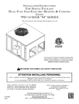
IX. Condensate Drain
Condensate Drain Connection
The evaporator condensate drain connection is 3/4" FPT.
Clean out the inside of the drain connection to assure
good condensate water runoff before connecting drain
line. The drain line should have a trap on it to prevent
debris, insects and dirt from being drawn into the return
air system. Refer to Figure 11 for location. A 1" mini-
mum head is recommended to allow draining against
the negative pressure inside the unit.
Pitch Toward Drain
Trap
1" Minimum
Condensate
Drain Connection
The Drain Connection Must
Be The Same Size as On
Unit or Larger
Figure 11
Typical Condensate Drain
NOTE: To avoid double trapping and an overflowing
drain pan, soft plastic drain lines are not recommended.

17
Air Circulation Blower
Gas Valve
Ignitor
Pressure Switch
(N.O. Contacts)
Combustion Blower
Thermostat
ON
OFF
ON
OFF
ON
OFF
ON
OFF
OPEN
CLOSED
CLOSED
OPEN
Seconds 0 34 38 110 0 90
Thermostat ON
Gas Valve Opens
Ignitor OFF
Air Blower ON
Thermostat OFF
Combustion Product
Purge Ends.
Air Blower OFF
Combustion
Blower OFF
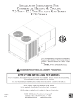
Figure 12
Timing Chart for Normal Robertshaw Operation (PGB & PGC)
Figure 13B
PGC Timing Chart for Normal Cooling Operation
On
Off
On
Off
On
Off
Seconds 0 30 0 30
(approx.) (approx.)
Indoor Fan
Outdoor Fan
and
Compressor
Thermostat
Figure 13A
PGB Timing Chart for Normal Cooling Operation
On
Off
On
Off
On
Off
Seconds 0 15 0 45
(approx.) (approx.)
Indoor Fan
Outdoor Fan
and
Compressor
Thermostat

18
X. Heating Sequence of Operations
PGB & PGC)
Normal Sequence of Operation - Heating
See Figure 12
1. Thermostat calls for heat. The combustion blower is
immediately energized.
2. The pressure switch contacts transfer.
3. The ignitor is energized and allowed to preheat for
38 seconds.
4. The gas valve is energized delivering gas to the
burners and starting combustion.
5. The control checks the signal from the flame sen-
sor. Gas flow will continue only if a proper signal is
present within seven seconds after the gas valve
opens. As soon as flame is proven, the ignitor is de-
energized.
6. The unit will continue to fire while the helical fan
control heats up. The fan control will start the main
circulating air blower approximately 75 seconds af-
ter the gas valve opens (this time may vary depend-
ing on the control setting).
7. The furnace will deliver heat to the conditioned space
until the thermostat is satisfied.
8. The gas valve and combustion blower will be de-
energized when the thermostat opens.
9. There is a 90 second delay (approximate) before
the main air blower stops. This allows any additional
heat in the heat exchanger to be transferred to the
conditioned space.
XI. Cooling Sequence of Operations
PGB Normal Sequence of Operations - Cooling
See Figure 13A
1. Thermostat calls for cooling. The compressor and
outdoor fan are energized.
2. Approximately 15 seconds later, the fan time delay
relay closes. The indoor fan now begins operation.
3. The unit will deliver cooling to the conditioned space
until the thermostat is satisfied.
4. The compressor and outdoor fan will be de-ener-
gized when the thermostat opens. It is normal for
the scroll compressor to produce a short burping
sound at this time as its internal pressures are equal-
ized.
5. Refrigerant will continue to flow through the capil-
lary tube (sizes 24 to 42) until the high and low side
pressures are approximately equal. Refrigerant will
continue to flow through the thermal expansion valve
until the high and low side pressures are approxi-
mately 50 PSI apart.
6. The indoor fan continues to run for approximately
45 seconds after the thermostat is satisfied. This
allows additional cooling from the indoor coil to be
transferred to the conditioned space.
PGC Normal Sequence of Operations - Cooling
See Figure 13B
1. Thermostat calls for cooling. The compressor, in-
door fan, and outdoor fan are energized.
2. Approximately 30 seconds later, the indoor fan
ramps up to full speed.
3. The unit will deliver cooling to the conditioned space
until the thermostat is satisfied.
4. The compressor and outdoor fan will be de-ener-
gized when the thermostat opens. It is normal for
the scroll compressor to produce a short burping
sound at this time as its internal pressures are equal-
ized. (The PGC48 has a piston compressor. All other
PGC and PGB have scroll compressors.)
5. Refrigerant will continue to flow through the capil-
lary tube (sizes 24 to 42) until the high and low side
pressures are approximately equal. For the PGC48,
60 and PGB58 refrigerant will continue to flow
through the thermal expansion valve until the high
and low side pressures are approximately 50 PSI
apart.
6. The indoor fan continues to run for approximately
30 seconds after the thermostat is satisfied. This
allows additional cooling from the indoor coil to be
transferred to the conditioned space. Then, the in-
door fan ramps down in 30 seconds to the OFF con-
dition.
XIl. Startup and Adjustment
Heating Startup
General Information
This furnace is equipped with an electronic ignition de-
vice which lights the burners. It also has a power vent
blower to exhaust combustion products.
On new installations, or if a major part such as the gas
valve, pressure switch or fan/limit control has been re-
placed, the operation of the furnace must be checked.
Check furnace operation as outlined in the following in-
structions. If any sparking, odors, or unusual noises are
encountered, shut off electrical power and recheck for
wiring errors, or obstructions in or near the blower mo-
tors. Various shipping materials must be removed be-
fore the indoor and outdoor fans can be operated.
Heat Anticipator Setting
The heat anticipator in the room thermostat must be
correctly adjusted to obtain the proper number of heat-
ing cycles per hour and to prevent the room tempera-
ture from over-shooting the room thermostat setting.
Heat anticipator must be set at 0.8 amps.
Roll-out Protection Control
If the flames from the burners are not properly drawn
into the heat exchanger, a protection device will open,
causing the gas valve to close. The protection device is
located on the manifold assembly (Figure 14).

19
WARNING
To avoid the risk of fire or explosion, a
qualified servicer must investigate the
problem which caused the roll-out pro-
tection device to open before manually
resetting the device.
Flame Roll-Out
Protector
(Manual Reset)
Figure 14
Rollout Protection
(Shown Without Heat Shield)
Secondary Limit Control
On the PGC and PGB series, a second limit control is
placed on the blower scroll that will open if the blower
should fail, causing elevated temperatures at the con-
trol. The reason for elevated temperatures at the control
should be ascertained and repaired prior to resetting this
manual reset control. The secondary limit control is lo-
cated behind the front center panel on the blower scroll.
(Figure 15).
Secondary Limit
Control
NOTE: Position of Limit Control
Differs From Model to Model.
Figure 15
Position of Limit Control
Reset After Lock-out
Should ignition not be achieved after three tries for any
reason, it will be necessary to reset the electronic igni-
tion module. To reset, it is only necessary to turn the
thermostat below room temperature for thirty seconds,
and then reset it to the desired temperature. The fur-
nace may also be reset after lockout by disengaging the
electric disconnect switch to the furnace for thirty sec-
onds.
Operating Instructions (Heating)
NOTE: Figure 16 illustrates the proper gas valve mount-
ing location.
Flame Roll-Out
Protector
(Manual Reset)
Figure 16
Gas Valve
1. Close the manual gas valve external to the furnace.
2. Turn off the electrical power supply to the furnace.
3. Set the room thermostat to its lowest possible set-
ting.
4. Remove the right hand door on the front of the fur-
nace by removing screws.
5. This furnace is equipped with an ignition device
which automatically lights the burner. Do NOT try to
light burner by any other method.
6. Turn the gas control valve knob to the OFF position.
Do not force. (Figure 16).
7. Wait five minutes to clear out any gas.
8. Smell for gas, including near the ground. This is im-
portant because some types of gas are heavier than
air. If you have waited five minutes and you do smell
gas, immediately follow the instructions on Page 6
of this manual. If you have waited five minutes and
you do NOT smell gas, turn the gas control valve
knob to the ON position. (Figure 16).
9. Replace the door on the front of the furnace.
10.Open the manual gas valve external to the furnace.
11.Turn on the electrical power supply to the furnace.
12.Set the thermostat to desired setting.
NOTE: There is a one minute delay between thermo-
stat energizing and burner firing.

20
Gas Input And Pressures
Gas supply pressure and manifold pressure with the
burners operating must be as specified on the rating
plate.
Checking Gas Pressure
Gas inlet pressure should be checked and adjusted in
accordance to the type of fuel being consumed.
With Power And Gas Off:
1. Connect a water manometer or adequate gauge to
the manifold gas pressure tap of the gas valve.
As an alternative method, inlet gas pressure can also
be measured by removing the cap from the dripleg and
installing a predrilled cap with a hose fitting. (See Figure
17).
With Power And Gas On:
2. Put furnace into heating cycle and turn on all other
gas consuming appliances.
INLET GAS PRESSURE
Natural Min. 5.0" W.C., Max. 10.0" W.C.
Propane Min. 11.0" W.C., Max. 14.0" W.C.
Inlet Gas Pressure Must Not Exceed the Maximum Val-
ues shown in Table Above.
If operating pressures differ from above, make neces-
sary pressure regulator adjustments, check piping size,
etc., and/or consult with local utility.
Figure 17
Measuring Inlet Gas Pressure
Alternate Method
Check The Manifold Pressure
A tapped opening is provided in the gas valve to facili-
tate measurement of the manifold pressure. A U Tube
manometer having a scale range from 0 to 12 inches of
water should be used for this measurement. The mani-
fold pressure must be measured with the burners oper-
ating.
To adjust the pressure regulator, remove the adjustment
screw or cover on the gas valve. Turn out (counterclock-
wise) to decrease pressure, turn in (clockwise) to in-
crease pressure. Only small variations in gas flow should
be made by means of the pressure regulator adjustment.
In no case should the final manifold pressure vary more
than plus or minus 0.3 inches water column from the
specified pressure. Any major changes in flow should
be made by changing the size of the burner orifices.
Check The Gas Input (Natural Gas Only)
NOTE: On outdoor equipment, the gas input will vary
with the temperature of the gas. Rated input will be ob-
tained at approximately 10° F. With warmer ambient and
gas temperatures, the input will decrease. Example: At
70° F the input will decrease 12%.
To measure the gas input using the gas meter proceed
as follows:
1. Turn off gas supply to all other appliances except
the furnace.
2. With the furnace operating, time the smallest dial on
the meter for one complete revolution. If this is a 2
cubic foot dial, divide the seconds by 2; if it is a 1
cubic foot dial, use the seconds as is. This gives the
seconds per cubic foot of gas being delivered to the
furnace.
3. INPUT=GAS HTG VALUE x 3600 / SEC. PER CU-
BIC FOOT
Example: Natural gas with a heating value of 1000 BTU
per cubic foot and 34 seconds per cubic foot as deter-
mined by Step 2, then:
Input = 1000 x 3600 / 0.34 = 106,000 BTU per Hour.
NOTE: BTU content of the gas should be obtained
from the gas supplier. This measured input must not
be greater than shown on the unit rating plate.
4. Relight all other appliances turned off in Step 1
above. Be sure all pilot burners are operating.
Check Main Burner Flame
Flames should be stable, soft and blue, (dust may cause
orange tips but they must not be yellow). They should
extend directly outward from the burner without curling,
floating or lifting off.
Check Temperature Rise
Check the temperature rise through the unit by placing
thermometers in supply and return air registers as close
to the furnace as possible. Thermometers must not be
able to see the furnace heat exchangers, or false read-
ings could be obtained.
1. All registers must be open; all duct dampers must
be in their final (fully or partially open) position and
the unit operated for 15 minutes before taking read-
ings.
2. The temperature rise must be within the range speci-
fied on the rating plate.
NOTE: Air temperature rise is the temperature differ-
ence between supply and return air.
/