
Pg. 1
www.snapav.com Support: 866.838.5052
SM-RBX-8 Installation Manual
Installation Manual
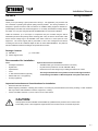
Strong VersaBox™SM-RBX-8
Overview
Thank you for purchasing a great product from Strong™. We appreciate your purchase and
are committed to providing the highest quality products possible. The Strong VersaBox™ is
designed to provide the best in-wall box solution for installers adding equipment behind low-
prole displays and other wall-mounted equipment. It can easily be installed in existing ceilings
and walls, or in new jobs using the optional SM-RBX-8-BKT Pre-Construction Bracket.
Inside the enclosure, up to two layers of components may be mounted using the built-in
attachment points and the pivoting center mounting plate. Easy-to-remove cutouts allow outlet
boxes and low-voltage rings to be installed in the sides of the box to save space for more
equipment. The center support plate is perforated to aid in wire management and device
mounting and can be set to different depths to allow for more varied installations. The plate can
also be modied as needed so that larger components t into the box.
Package Contents
(1) SM-RBX-8
(1) Center Support Plate
(1) Cover Plate
Important Instructions and Considerations for Installation
• Read and follow all instructions.
• Before beginning installation, carefully plan locations, accounting for potential electrical, ductwork, plumbing or other obstacles
that may interfere with installation of the box, equipment, or wiring.
• Contact a suitable contractor if you are unsure of how to best install.
Recommended for Installation
Tools
• #1 Phillips Screwdriver
• Drywall Saw
• Tape Measure
• Level
• ¼” Flat Head Screwdriver (optional)
• Electric Drill and ¼” bit (optional)
• Tin Snips (optional)
Optional Accessories and Hardware
• SM-RBX-8-BKT (pre-construction bracket for new work)
• Drywall screws (needed for use with SM-RBX-8-BKT)
• Electrical box and low voltage ring for adding terminations to cutouts
Use only standard size cover plates on boxes and rings installed
in the Strong VersaBox
TM
. Midi and jumbo size plates will not t.
This equipment must be installed and assembled by qualied service personnel in accordance with
local building codes. Total equipment weight stored in this enclosure must not exceed 50 pounds.
CAUTION:

Pg. 2
www.snapav.com Support: 866.838.5052
SM-RBX-8 Installation Manual
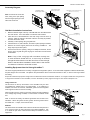
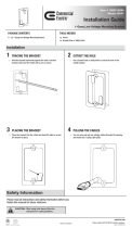
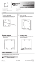
Old Work Installation Instructions
1. Mark the desired height of the top of the SM-RBX-8 on the wall between
two stud centers. Use a stud nder to locate the stud locations.
2. Press the rear of the SM-RBX-8 to the wall, using a level to line it up
correctly. Mark the outline of the back of the box as neatly as possible,
and then set the box aside.
3. Carefully cut the opening using a drywall saw.
4. After the hole is cut, test t the box, and clean up the opening as needed.
5. Remove the center support plate from the Strong VersaBox™. The
hinge clips may be left in place.
6. Insert the box into the opening. Using a #1 Phillips screwdriver, secure
the box to the drywall using the dog legs on each side of the enclosure
as illustrated.
Using Knockouts
The knockouts on the top and bottom of the VersaBox may be used
for installing low voltage rings or for outlet boxes. If an outlet box is
installed, it must be an old work, residential grade box with integrated
work supports to allow for secure mounting.
When knocking out the opening, leave the small screw tabs installed if
a low voltage ring is being mounted, or remove them to install an outlet
box.
Note: To ensure re safety, the silicone grommets must remain in the
VersaBox. When using these as wire guides, slit each grommet down
the middle in a “+” shape, never remove them.
Modules
The back wall of the VersaBox has holes and knockouts stamped into it
on 6” centers to allow for easy structured can module installation. Use
a ¼” drill bit to open more of the knockout stamps as needed to mount
equipment.
Installing Equipment into the Strong VersaBox™
The center support plate allows for a variety of equipment conguration options. To accommodate equipment of different thicknesses,
the plate hinges can be reversed. The plate is also perforated so that it can be trimmed down in size, or used for securing modules
and wiring.
Experiment with the equipment configuration to determine the best installation method. For images of different configurations
of equipment installed in the VersaBox, see the VersaBox product page and Support Tab at www.SnapAV.com.
Note: If any of the 4 dog legs will not extend correctly due
to stud clearance beside the box, a screw may be inserted
through the side of the box into the stud if one is close enough.
Refer to the New Work Installation section later in the manual
for reference of where to insert the screw/s.
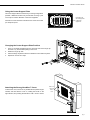
Assembly Diagram
Note: To remove the cover with
ease, swing door open pulling
from the nger openings on the
side of the cover rst.
Adjustable Position
Center Support Plate
Single Gang Enclosure
Mounting on all 4 sides
Optional New Work Pre-Construction Ring
(
SM-RBX-8 -BKT, sold separately)
Tighten
Dogleg
S
crews with
#1 Phillips
S
crewdriver
Cutout Dimensions
14.25" (W) x 8.5" (H)
Horizontal

Pg. 3
www.snapav.com Support: 866.838.5052
SM-RBX-8 Installation Manual
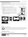
Using the Center Support Plate
Changing the Center Support Plate Position
Attaching the Strong VersaBox™ Cover
The center support allows for almost any mounting conguration
possible. Additional sections may be trimmed out using a pair
of tin snips for further utilization of mounted equipment.
Dimensions in the illustration indicate the size of the removable
pre-stamped square.
1. Insert ¼” at head screwdriver into the slot at the rear of the hinge clip
and twist. Pry forward while pulling to remove it.
2. Rotate the hinge clip 180°.
3. Press the hinge clip back in with the screwdriver until it clicks into place.
4. Repeat for each of the 4 clips.
To attach the cover, knock out any additional wire pass-throughs
needed, and then slid the cover on, seating the hooks on the
right side rst, and pushing the left side in until a “click” is heard.
Perforations for
wire managemen
t
or attaching
equipment
A
B
C
Insert
hooks
on one
side rst
Push in on
opposite
side to
close

Pg. 4
www.snapav.com Support: 866.838.5052
SM-RBX-8 Installation Manual
Dimensions
Warranty
Limited Lifetime Warranty
All Strong back-boxes and brackets have a Lifetime Limited Warranty. This warranty includes parts and labor repairs on all
components found to be defective in material or workmanship under normal conditions of use. This warranty shall not apply to
products that have been abused, modied, or disassembled. Products to be repaired under this warranty must be returned to
SnapAV or a designated service center with prior notication and an assigned return authorization number (RA).
Lifetime
Contacting Technical Support
Phone: (866) 838-5052 Email: Techsupport@snapav.com
© 2014 Strong™
140602-1400
New Work Installation Instructions
The SM-RBX-8-BKT Pre-Construction Bracket is designed to prepare a location for the Strong In-Wall VersaBox in new work
applications before drywall is hung on the studs.
Note: Determine what thickness the drywall will be before installing the pre-construction bracket. If the studs are wider than 16” use
dog ears.
Strong VersaBox™ Installation (after drywall is installed)
1. Remove the center support plate from the VersaBox. The hinge clips may be
left installed.
2. Open any knockouts in the VersaBox that will be used for wiring or electrical.
3. Pull the wires out of the wall opening and pull them into the desired openings
of the VersaBox.
4. Insert the box into the opening left where the bracket is. Use standard drywall
screws to secure the box to the studs on each side of the enclosure as
illustrated.
See the documentation included with the SM-RBX-8 In-Wall VersaBox or go
to the SM-RBX-8 product page at www.SnapAV.com for tips and instructions
to install equipment into the VersaBox.
9.34 in.
15.3 in.
14 in.
1.65 in.
2.06 in.
2.27 in.
1.44 in.
7.87 in.
3.80 in.
Tighten
Dogleg
S
crews with
#1 Phillips
S
crewdriver
Cutout Dimensions
14.25"(W) x8.5" (H)
Vertical
-
 1
1
-
 2
2
-
 3
3
-
 4
4


Strong SM-RBX-8-WH Owner's manual
- Type
- Owner's manual
- This manual is also suitable for
Ask a question and I''ll find the answer in the document
Finding information in a document is now easier with AI
Related papers
-
Strong SM-RBX-14-WH Owner's manual
-
-
-
-
-
-
-
-
-
Other documents
-
 Cerro 630-WRKBRKT1 Operating instructions
-
 Commercial Electric 5042 Operating instructions
-
 Commercial Electric 5042 Operating instructions
-
 Calculated Industries 8105 User guide
-
 Calculated Industries 8120 User manual
-
Control4 WB-300VB-IP-5 Installation guide
-
-
Episode IW-8 Installation guide
-
Episode ES-350T-IC-6 Installation guide
-
Episode EE-ACC-ST-TRM-M-10PK Quick start guide


