Page is loading ...

Installation Guide
English
Freestanding
Water Optimizer
Freestanding Purier·Dispenser
Model: KM5K
Customer Assistance
1-844-374-6576
www.kenmore.com
Kenmore and the Kenmore logo are the registered
trademarks of KCD IP, LLC and/or Sears Brands, LLC
and are used under license by Drinkpod, LLC
All Rights Reserved.

Table Of Contents
IMPORTANT SAFETY INSTRUCTIONS 1
GETTING STARTED 1-2
Installation Components List 1-2
Conguration & Location 2-4
Preparation 2-9
Tapping Water Source 2-11
INSTALLING YOUR WATER OPTIMIZER 2-11
Running Water Source Line 2-23
Flushing Your Filters 2-26
Connecting Accessory Appliances 2-33
Connecting Water Optimizer 2-43
Installing Filters 2-46
Optional - Expanding Purication Capabilities 2-49
Enabling Water Flow 2-51
APPENDIXES 2-54
Appendix A - Water Sources 2-54
Appendix B - Component Connections 2-57
OPERATING YOUR WATER OPTIMIZER 2-62
Table of Contents

Important Safety Instructions
Important Safety Instructions 1
When using electrical appliances, basic safety precautions should always be followed,
including the following:
1. Read all instructions.
2. Should your appliance ever fail, please disconnect the power and water immediately before
calling for assistance.
3. To avoid leakage and damage, never remove appliance parts.
4. Unsupervised children should not be allowed to operate the machine.
5. Please use the product in a dry place within the temperature ranges of 40°F and 100°F.
6. Ensure the power cord is always unplugged before performing any maintenance,
troubleshooting, or lter upgrades.
7. Only use Kenmore or Drinkpod accessories and lters to avoid causing damage and voiding
product warranty.
8. For all service and support related issues, please contact Drinkpod. 1-844-374-6576 or
9. Any and all repairs should only be attempted by qualied persons designated by Drinkpod.
10. Do not install the machine in a location exposed to direct sunlight.
11. Never store or expose your Water Optimizer in an environment less than 32°F.
12. This appliance is not intended for use by persons with reduced physical, sensory, or mental
capabilities, or lack of experience and knowledge, unless they have been given supervision or
instruction concerning use of the appliance by a person responsible for their safety. Children
should be supervised to ensure they do not play with the appliance.
13. If the supply cord is damaged, it must be replaced by the manufacturer, one of its designated
service agents, or similarly qualied person, in order to avoid all hazards.
14. Do not store explosive substances such as aerosol cans, or other items with a ammable
propellant, in this appliance.
15. This appliance is intended to be used in household and similar applications, kitchens, oces,
and similar non-retail applications.
16. The appliance should only be plugged into a grounded three prong socket. A surge protector is
recommended.
17. The appliance should never be turned upside down, or tilted more than 45°.
18. The appliance should never be cleaned utilizing a compressed water stream.
19. This product is designed for household use only!
20. WARNING: To avoid any hazards due to instability of the appliance, it must be
installed, maintained, and repaired, in accordance with this manual.
SAVE THESE INSTRUCTIONS!
IMPORTANT SAFETY INSTRUCTIONS

Getting Started
Getting Started 1-2
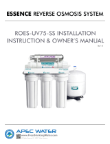
Installation Components List
Included with your Water Optimizer are a broad assortment of installation accessories. Do
not get overwhelmed. While it is highly unlikely that you will require all of them, working
with anything connected to your homes water system can be the wild west, and plumbers
are rogue gunslingers. That’s why we’ve done our best to provide enough accessories
to accommodate almost any scenario, and easy to understand instructions to guide you
through the process.
We highly recommend leaving the installation accessories in their labeled tray
until you are instructed to remove them.
GETTING STARTED
A
B
C
C
D E
F
G

Getting Started
Getting Started 1-3
A: 25’ Coil of 1/4 in. White PP Tubing
B: 1/4 in. Compression To Quick Connect Adapter (x6)
C: 1/4 in. Quick Connect Shuto Valve (x2)
D: 1/4 in. Brass Compression Union
E: 1/4 in. Brass Compression Tee
F: 3/8 in. Sink Adapter Valve (1/4 in. Custom x 3/8 in. Male x 3/8 in. Female x
Compression Steel Angle Stop Valve Adapter)
G: Filter Flushing Attachment

Getting Started
Getting Started 2-4
Before we proceed with your installation, we must rst identify how and where to install
your new Water Optimizer. This will be the most complicated part of the installation
process. Don’t be intimidated! We’ve worked hard to write the best set of instructions you’ll
ever read. Be prepared to feel like a DIY pro when you’re nished!
Conguration & Location
First, let’s decide where you want to install your Water Optimizer. In almost all cases, this
easily decided by answering two simple questions.
1. What water sources are available? If you’re not sure what you have, or how to check,
see “Appendix A - Water Sources” on page 2-53 for pictures and more information.
A.
Water Accessory Line (typically refrigerator ice maker line/source)
B.
Sink Faucet Cold Water Line (i.e. underneath your kitchen sink)
2. Do you want to connect any other appliances? Your Water Optimizer is capable of
providing puried water to up to two kitchen appliances* (i.e. refrigerator, ice maker, or
coee maker/espresso maker/barista machine with an in-line water connection).
*The ability to provide purified water to external appliances is dependent on having
sufficient water pressure.
3. Following this are diagrams of the most common types of installations our customers
like to use. Quickly review them to identify which conguration best suits you. We
recommend connecting to a Water Accessory Line if both types of water sources are
available.

Getting Started
Getting Started 2-5
Accessory Water Line Congurations
Example Installation #1.1
Accessory Water Line Source
BEFORE
Accessory Water Source
(Ice Maker)
AFTER
Accessory Water Source
(Ice Maker)
Water Optimizer
(Ice Maker Connection)
Diagram 2.1.1-A Accessory Water Line Source (Not Connected, No Accessory Appliances)
Example Installation #1.2
Accessory Water Line Source - 1x Accessory Appliance
BEFORE
Accessory
Water Source
Refrigerator
(Ice Maker Connection)
AFTER
Accessory
Water Source
Refrigerator
(Ice Maker Connection)
Water
Optimizer
Diagram 2.1.1-B Accessory Water Line Source (Connected, 1 Accessory Appliance)
source
source
acc.
0x
acc.
1x

Getting Started
Getting Started 2-6
Example Installation #1.3
Accessory Water Line Source - 2x Accessory Appliances
BEFORE
Accessory
Water Source
Refrigerator
(Ice Maker Connection)
AFTER
Accessory
Water Source
Refrigerator
(Ice Maker Connection)
Water
Optimizer
Coffee Maker
(Input Port)
Diagram 2.1.1-C Accessory Water Line Source (Connected, 2 Accessory Appliances)
Sink Faucet Cold Water Line Congurations
Example Installation #2.1
Sink Faucet Cold Water Line Source
BEFORE
Sink Faucet Water Source
(Under Kitchen Sink)
AFTER
Water Optimizer
(Sink Faucet Connection)
Sink Faucet Water Source
(Under Kitchen Sink)
Diagram 2.1.2-A Faucet Cold Water Line Source (No Accessory Appliances)
source
acc.
0x
source
acc.
2x

Getting Started
Getting Started 2-7
Water
Optimizer
Refrigerator
(Ice Maker Connection)
Refrigerator
(Ice Maker Connection)
Example Installation #2.2
Sink Faucet Cold Water Line Source - 1x Accessory Appliance
BEFORE
Sink Faucet Water Source
(Under Kitchen Sink)
Sink Faucet Water Source
(Under Kitchen Sink)
AFTER
Accessory
Water Source
Diagram 2.1.2-B Faucet Cold Water Line Source (1 Accessory Appliance)
Water
Optimizer
Coffee Maker
(Input Port)
Refrigerator
(Ice Maker Connection)
Refrigerator
(Ice Maker Connection)
Example Installation #2.3
Sink Faucet Cold Water Line Source - 2x Accessory Appliances
BEFORE
Sink Faucet Water Source
(Under Kitchen Sink)
Sink Faucet Water Source
(Under Kitchen Sink)
AFTER
Accessory
Water Source
Diagram 2.1.2-C Faucet Cold Water Line Source (2 Accessory Appliances)
source
source
acc.
2x
acc.
1x

Getting Started
Getting Started 2-8
Alternative Conguration
Example Installation #3
Accessory Water Line Source - Low Pressure Alternative
BEFORE
Accessory
Water Source
Refrigerator
(Ice Maker Connection)
AFTER
Accessory
Water Source
Refrigerator
(Ice Maker Connection)
Water
Optimizer
Diagram 2.1.3 Low Water Pressure Alternative (Shared in Parallel)
4. It’s almost time to choose where to install your new Water Optimizer. You should have a
pretty good idea based on available space and whichever conguration you selected.
There’s only one remaining factor you need to consider, and that is your tubing (water
lines).
5. Your water source, Optimizer, and any accessory appliances all need to be connected
by the white ¼ in. PP tubing (included in your installation kit) or existing water line
hose. Take a moment to visualize where you’ll need to run your water tubing, and visually
inspect any potential trouble areas, and adjust your plans accordingly. Below are a two
examples:
A.
Cabinets separating your Optimizer from a water source or appliance, requiring
you to route tubing over/under, or drill holes.
B.
Lack of vertical access from your water source under your sink to above your
counter-top, requiring drilling holes to run the tubing inside your cabinets, or
through your counter-top.
Congratulations, the most dicult part is out of the way! Let’s get started
source
acc.
P

Getting Started
Getting Started 2-9
Preparation
Before we start tapping your water source, there are a few items you need to grab that
weren’t included in your installation kit.
•
Sharp Knife or Scissors
•
Pliers, or Adjustable Wrench, or Open-End 7/16 in. Wrench (all installations),
1/2 in. Wrench (most installations), and 11/16 in. Wrench (*sink water source
installation only)
•
Container To Drain Water Into (i.e. bucket, bowl, or pitcher)
•
Flashlight or Lamp (if under sink installation area is poorly lit)
•
Drill (if drilling holes to run tubing is required)
or or or
+
1/2 in.
+
7/16 in.
11/16 in.
*
Diagram 2.0.1 Additional Items Needed For Installation
1. Remove the Optimizer and lters from the packaging and set them aside.
2. Let’s get started. If your plan is to utilize your Accessory Water Line as your source,
proceed below for Option A (Accessory Water Line). Alternatively, if you plan to use
your sink faucet cold water line as your source, turn to “Option B: Tapping Faucet


Installing Your Water Optimizer
Installing Your Water Optimizer 2-11
Tapping Water Source
source
Option A: Tapping Accessory Water Line
In this section, you will require 1/4 in. White PP Tubing, and may also need
B
1/4 in. Compression To Quick Connect Adapter, and pliers, or an adjustable wrench or
1/2 in. wrench.
1. If nothing is currently connected to your water accessory line, skip forward to Step
#7 on page 2-14.
2. If appliance is connected to water accessory line, start by powering o and
unplugging the appliance.
3. Pull the refrigerator (or other appliance) away from wall suciently to allow access to
wall and oor behind it.
Diagram 2.3A.3 Pulling Back Appliance To Access Water Source Line & Valve
4. In most scenarios, your shuto valve and connection will look similar to the rst diagram
below. We’ve also included the second and third most common setups in the proceeding
diagrams. The instructions should remain accurate, regardless of which setup yours is, as
long as it incorporates a shuto valve. Should the latter not be the case, you will have to
locate the shuto valve before proceeding.
INSTALLING YOUR WATER OPTIMIZER
A

Installing Your Water Optimizer
Installing Your Water Optimizer 2-12
Diagram 2.3(A).4-A Wall Mounted Accessory Water Line Source
Diagram 2.3(A).4-B Floor Mounted Accessory Water Line Source

Installing Your Water Optimizer
Installing Your Water Optimizer 2-13
Diagram 2.3(A).4-C Unmounted/Free Accessory Water Line Source
5. Turn the valve handle clockwise until it stops to shut o water ow.
Diagram 2.3(A).5-A/B Closing Source Valve

Installing Your Water Optimizer
Installing Your Water Optimizer 2-14
6. Now, use pliers, adjustable or 1/2 in. wrench, to disconnect the appliance water line
from the source shuto valve. If you’re unsure how to disconnect the water line, see
“Appendix B - Component Connections” on page 2-57. If its already adapted to
quick connect (see ) leave the adapter, and disconnect the tubing.
Diagram 2.3(A).6-A Disconnect Appliance Water Line (Compression)
Diagram 2.3(A).6-B Disconnect Appliance Water Line (Quick Connect)
7. If the water source shuto valve isn’t already Quick Connect, connect
B
1/4 in. Compression To Quick Connect Adapter to Accessory Water Line Shuto

Installing Your Water Optimizer
Installing Your Water Optimizer 2-15
Valve.
Diagram 2.3(A).7 Connect Compression-To-Quick Connect Adapter
8. Connect one end of 1/4 in. White PP Tubing to
B
1/4 in. Compression To Quick Connect Adapter.
Diagram 2.3(A).8 Connect Tubing To Water Source
9. Congratulations! You’ve just completed the second most dicult part of your installation.
Now jump ahead to “Running Water Source Line Step #4” on page 2-23.
A

Installing Your Water Optimizer
Installing Your Water Optimizer 2-16
source
Option B: Tapping Faucet Cold Water Line
1. For this section, you will need
F
3/8 in. Sink Adapter Valve, as well as pliers, a
crescent wrench, or 7/16 in. and 11/16 in. open ended wrenches (see “Preparation” on
page 2-9).
Diagram 2.3(B).1 Connect Compression-To-Quick Connect Adapter
2. Open your cabinet doors to reveal the plumbing underneath your sink. Don’t get
overwhelmed by all the piping and connections. We’ve provided a diagram with
labels to help you understand what you’re looking at (accurate for most under sink
setups). The blue items listed below are ll that we’ll be working with.
KS-A:
Left Drain
KS-B:
Hot Faucet Handle
KS-C:
Hot Water Feed Line
KS-D:
Hot Water Shuto Valve
KS-E:
Faucet
KS-F:
Cold Water Shuto Valve
KS-G:
Cold Water Feed Line
KS-H:
Cold Faucet Handle
KS-I:
Garbage Disposal

Installing Your Water Optimizer
Installing Your Water Optimizer 2-17
KS-J:
Right Drain
Diagram 2.3(B).2 Under Sink Reference Diagram
3. We will be tapping the cold water line, which is typically on the right, but its always
smart to conrm the plumber didn’t take any ‘creative liberties’. Begin by turning on the
cold water at your faucet
KS-H
. .
KS-E
KS-H
KS-I
KS-J
KS-B
KS-A
KS-D
KS-C KS-G
KS-F

Installing Your Water Optimizer
Installing Your Water Optimizer 2-18
Diagram 2.3(B).3 Turn On Cold Water In Sink
4. Now turn the handle of
KS-F
Cold Water Shuto Valve clockwise until it won’t turn
any further. If your faucet stops pouring water, we’ve conrmed this is your cold water
shuto. If it doesn’t turn o, then it is the valve on the left.
Diagram 2.3(B).4 Shuto Cold Water Source Valve
5. Use our pliers, crescent wrench, or 11/16 in. wrench to loosen
KS-G
Cold Water Feed Line from
KS-F
Cold Water Shuto Valve. IF THE WRENCH
FITS, continue to loosen and detach the hose, and proceed. IF IT DOESN’T FIT, the
/