Wacker Neuson CUB700 User manual

Type
User manual

This manual is also suitable for

Operator’s Manual
Indirect-Fired Air Heaters
Cub 400
Cub 700
0170815en 005 1109
Copyright
notice
© Copyright 2009 by Wacker Neuson Corporation.
All rights, including copying and distribution rights, are reserved.
This publication may be photocopied by the original purchaser of the machine. Any
other type of reproduction is prohibited without express written permission from
Wacker Neuson Corporation.
Any type of reproduction or distribution not authorized by Wacker Neuson Corporation
represents an infringement of valid copyrights. Violators will be prosecuted.
Trademarks
All trademarks referenced in this manual are the property of their respective owners.
Manufacturer
Wacker Neuson Corporation
N92W15000 Anthony Avenue
Menomonee Falls, WI 53051 U.S.A.
Tel: (262) 255-0500 · Fax: (262) 255-0550 · Tel: (800) 770-0957
www.wackerneuson.com
Original
instructions
This Operator’s Manual presents the original instructions. The original language of this
Operator’s Manual is American English.
Foreword
ghi_tx001366gb.fm 3
Foreword
Machines
covered by
this manual
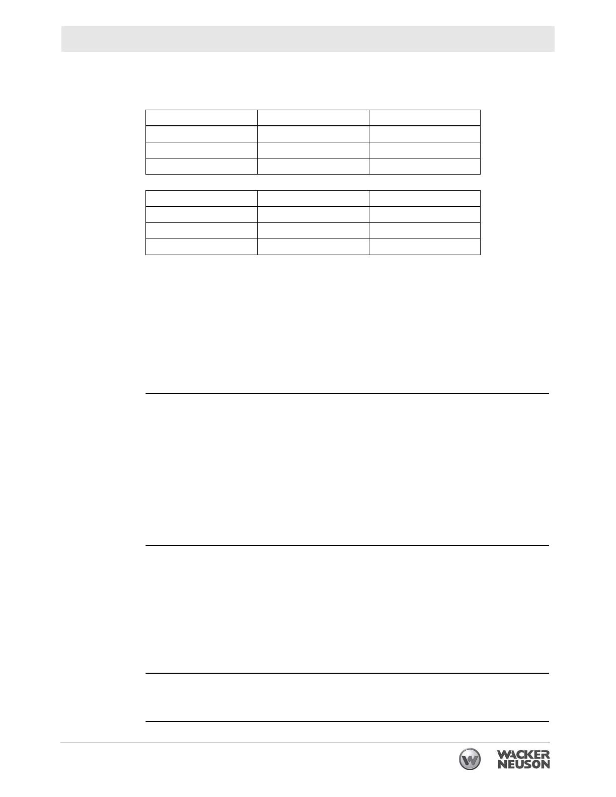
This manual covers machines with the following item numbers:
Machine
documentation
Keep a copy of the Operator’s Manual with the machine at all times.
Use the separate Parts Book supplied with the machine to order replacement
parts.
If you are missing any of these documents, please contact Wacker Neuson
Corporation to order a replacement or visit www.wackerneuson.com.
When ordering parts or requesting service information, be prepared to provide
the machine model number, item number, revision number, and serial number.
Expectations
for
information in
this manual
This manual provides information and procedures to safely operate and main-
tain the above Wacker Neuson model(s). For your own safety and to reduce the
risk of injury, carefully read, understand, and observe all instructions described
in this manual.
Wacker Neuson Corporation expressly reserves the right to make technical
modifications, even without notice, which improve the performance or safety
standards of its machines.
The information contained in this manual is based on machines manufactured
up until the time of publication. Wacker Neuson Corporation reserves the right
to change any portion of this information without notice.
Copyright
notice
All rights, especially copying and distribution rights, are reserved.
Copyright 2009 by Wacker Neuson Corporation.
This publication may be reproduced through photocopying by the original pur-
chaser of the machine. Any other type of reproduction is prohibited without
express written permission from Wacker Neuson Corporation.
Any type of reproduction or distribution not authorized by Wacker Neuson Cor-
poration represents an infringement of valid copyrights, and violators will be
prosecuted.
Trademarks
All trademarks referenced in this manual are the property of their respective own-
ers.
Machine Item Number Revison
Cub 400 0620206 199 and below
Cub 400 0620211 199 and below
Cub 400 0620212 199 and below
Machine Item Number Revison
Cub 700 0620208 199 and below
Cub 700 0620213 199 and below
Cub 700 0620207 199 and below
Foreword
4 ghi_tx001366gb.fm
Manufacturers
approval
This manual contains several references to approved parts, attachments, and mod-
ifications. The following definitions apply:
Approved parts or attachments are those either manufactured or provided by
Wacker Neuson.
Approved modifications are those performed by an authorized Wacker Neu-
son service center according to written instructions published by Wacker Neu-
son.
Unapproved parts, attachments, and modifications are those that do not
meet the approved criteria.
Unapproved parts, attachments, or modifications may have the following conse-
quences:
Serious injury hazards to the operator and persons in the work area
Permanent damage to the machine which will not be covered under warranty
Contact your Wacker Neuson dealer immediately if you have questions about
approved or unapproved parts, attachments, or modifications.
CALIFORNIA
Proposition
65 Warning:
Diesel engine exhaust, some of its constituents, and certain vehicle components,
contain or emit chemicals known to the State of California to cause cancer and
birth defects or other reproductive harm.
Cub 400/700 Table of Contents
wcghi_bo0170815en_005TOC.fm 5
Foreword 3
1 Safety Information 7
1.1 Signal Words Found in this Manual ...................................................... 7
1.2 Operating Safety .................................................................................. 8
1.3 Operator Safety while using Combustion Burners ............................... 9
1.4 Service Safety .................................................................................... 10
1.5 Label Locations .................................................................................. 11
1.6 Safety and Operating Labels .............................................................. 12
2 Operation 13
2.1 System Description ............................................................................ 13
2.2 Installing the Lift Bar ........................................................................... 14
2.3 Machine Location ............................................................................... 15
2.4 System Component Locations ........................................................... 16
2.5 Control Panel ...................................................................................... 17
2.6 Preliminary Checks ............................................................................ 18
2.7 Starting the Machine .......................................................................... 18
2.8 Preheating the Fuel Filter ................................................................... 19
2.9 Shutting Down the Machine ............................................................... 20
2.10 Using the Remote Thermostat ........................................................... 21
2.11 Suggested Venting ............................................................................. 22
2.12 Adjusting the Recirculation System .................................................... 24
2.13 Connecting the Main Electric Power Supply ...................................... 25
2.14 Installing the Plenums ........................................................................ 26
2.15 Checking the Burner Air Setting ......................................................... 27
3 Maintenance 29
3.1 Periodic Maintenance Schedule ......................................................... 29
3.2 Changing and Adjusting the Supply Blower Belt ................................ 30
3.3 Replacing the Oil Burner Nozzle ........................................................ 32
3.4 Changing the Fuel Heater Filter ......................................................... 34
3.5 Checking and Adjusting the Electrode and Ionization Probe ............. 36
3.6 Checking Function of Ionization Probe ............................................... 37
3.7 Maintaining the Heater Weldment ...................................................... 38
Table of Contents Cub 400/700
6 wcghi_bo0170815en_005TOC.fm
3.8 Transporting ........................................................................................40
3.9 List of Abbreviations ............................................................................41
3.10 Troubleshooting ...................................................................................42
4 Schematics 44
4.1 Cub 400—Oil Burning .........................................................................44
4.2 Cub 400 Components—Oil Burning ....................................................45
4.3 Cub 700—Oil Burning .........................................................................46
4.4 Cub 700 Components—Oil Burning ....................................................47
4.5 Cub 400—Gas Burning .......................................................................48
4.6 Cub 400 Components—Gas Burning ..................................................49
4.7 Cub 700—Gas Burning .......................................................................50
4.8 Cub 700 Components—Gas Burning ..................................................51
5 Technical Data 52
5.1 Cub 400 Technical Data ......................................................................52
Cub 400/700 Safety Information
wcghi_si000198gb.fm 7
1 Safety Information
1.1 Signal Words Found in this Manual
NOTICE: Used without the safety alert symbol, NOTICE indicates a
situation which, if not avoided, could result in property damage.
Note: A Note contains additional information important to a procedure.
This is the safety alert symbol. It is used to alert you to potential personal hazards.
f Obey all safety messages that follow this symbol.
DANGER
DANGER indicates a hazardous situation which, if not avoided, will result in death
or serious injury.
f To avoid death or serious injury from this type of hazard, obey all safety mes-
sages that follow this signal word.
WARNING
WARNING indicates a hazardous situation which, if not avoided, could result in
death or serious injury.
f To avoid possible death or serious injury from this type of hazard, obey all safety
messages that follow this signal word.
CAUTION
CAUTION indicates a hazardous situation which, if not avoided, could result in
minor or moderate injury.
f To avoid possible minor or moderate injury from this type of hazard, obey all
safety messages that follow this signal word.
Safety Information Cub 400/700
8 wcghi_si000198gb.fm
1.2 Operating Safety
Familiarity and proper training are required for the safe operation of
this machine. Machines operated improperly or by untrained personnel
can be dangerous. Read the operating instructions contained in both
this manual and the OEM manuals included with this machine.
Familiarize yourself with the location and proper use of all controls.
Inexperienced operators should receive instruction from someone
familiar with the machine before being allowed to operate it.
NEVER run the machine indoors or in an enclosed area unless
adequate ventilation, through such items as exhaust fans or hoses, is
provided. Exhaust gas from the genset and from the burner contains
carbon monoxide, a deadly poison. Exposure to carbon monoxide
WILL KILL YOU IN MINUTES.
Always use caution when applying power to the machine. Upon
applying power to the machine, the blower may start without warning.
1.2.1 Be sure the machine is on a firm, level surface and will not tip, roll,
slide, or fall while operating.
1.2.2 NEVER start a machine in need of repair.
1.2.3 Keep unauthorized personnel, children, and pets away from the
machine.
1.2.4 Always operate machine with all safety devices and guards in place
and in working order. Do not modify or defeat safety devices. Do not
operate machine if any safety devices or guards are missing or
inoperative.
1.2.5 Do not smoke while operating the machine.
1.2.6 NEVER run the machine in areas that contain flammable objects,
fuels, or products that produce flammable vapors.
1.2.7 NEVER connect ductwork between the exhaust outlet port and the
supply air inlet port.
WARNING
WARNING
CAUTION
Cub 400/700 Safety Information
wcghi_si000198gb.fm 9
1.3 Operator Safety while using Combustion Burners
Combustion burners present special hazards during operation and
fueling. Read and follow the warning instructions in the burner owner’s
manual and the safety guidelines below. Failure to follow the warnings
and safety guidelines could result in severe injury or death.
NEVER run the machine indoors or in an enclosed area unless
adequate ventilation, through such items as exhaust fans or hoses, is
provided. Exhaust gas from the genset and from the burner contains
carbon monoxide, a deadly poison. Exposure to carbon monoxide
WILL KILL YOU IN MINUTES.
1.3.1 Do not fill or drain the fuel tank near an open flame, while smoking, or
while the engine is running.
1.3.2 Refill the fuel tank in a well-ventilated area.
1.3.3 Replace the fuel tank cap after refueling.
1.3.4 DO NOT spill fuel when refueling the machine. Clean up spilled fuel
immediately.
1.3.5 DO NOT smoke when refueling machine.
1.3.6 DO NOT refuel a hot or running machine.
1.3.7 The machine must be installed by qualified personnel who have read
and understand all supplied manuals and instructions.
1.3.8 All connections to natural gas or LP must be performed by qualified
personnel who possess the proper certification or lincensing required
by the locality, state, or province in which the machine is being
installed.
WARNING
WARNING
Safety Information Cub 400/700
10 wcghi_si000198gb.fm
1.4 Service Safety
HIGH VOLTAGE! This unit uses high voltage circuits capable of
causing serious injury or death. Only a qualified electrician should
troubleshoot or repair electrical problems occurring with this
equipment.
1.4.1 All connections to natural gas or LP must be performed by qualified
personnel who possess the proper certification or lincensing required
by the locality, state, or province in which the machine is being
installed.
1.4.2 ALWAYS replace the safety devices and guards after repairs and
maintenance.
1.4.3 Keep the machine clean and labels legible. Replace all missing and
hard-to-read labels. Labels provide important operating instructions
and warn of dangers and hazards.
1.4.4 ALWAYS make sure slings, chains, hooks, ramps, jacks, and other
types of lifting devices are attached securely and have enough weight-
bearing capacity to lift or hold the machine safely. Always remain
aware of the location of other people in the area when lifting the
machine.
1.4.5 ALWAYS replace or repair electrical components with components
that are identical in rating and performance as the original component.
1.4.6 Do not use gasoline or other types of fuels or flammable solvents to
clean parts, especially in enclosed areas. Fumes from fuels and
solvents can become explosive.
WARNING
Cub 400/700 Safety Information
wcghi_si000198gb.fm 11
1.5 Label Locations
4
7
3
1
2
6
wcghi_gr004415
4
5
8
Safety Information Cub 400/700
12 wcghi_si000198gb.fm
1.6 Safety and Operating Labels
* Not used on NG and LP machines.
Ref. Label Ref Label
12
34
5* 6
7
Cub 400/700 Operation
wcghi_tx000683gb.fm 13
2 Operation
2.1 System Description
The Cub 400 and Cub 700 heaters are indirect-fired air heaters. The
Cub 400 and 700 have stainless steel fireboxes and heat exchangers.
They run on three fuel options: diesel, natural gas (NG), or LP. The fuel
is consumed in a closed combustion chamber. The exhaust gases are
vented outdoors through a vent pipe. The clean, dry hot air is blown or
ciculated in the space by a centrifugal blower. The blower assembly is
protected by a guard fitted on the air inlet.
Cub 400 and Cub 700 heaters are meant to heat air on construction
sites and in other rugged applications. Do not use the Cub 400 or Cub
700 for any other purpose.
Operation Cub 400/700
14 wcghi_tx000683gb.fm
2.2 Installing the Lift Bar
See graphic: wcghi_gr004433
The Cub 700 diesel with tank machine (item #: 0620213) is shipped
with the lift bar partially assembled. Before use, the lift bar must be
removed from its mounting location and installed on top of the
machine. To install the lift bar, carry out the following procedure:
2.2.1 Unpack the machine.
2.2.2 Remove and discard the bolts (a) that secure the lift bar to the side of
the machine.
2.2.3 Install the lift bar on top of the machine using the supplied 16 bolts (b).
Note: The bolts (b) are 3/8 inch 16X1.5 inches and are supplied in a
small plastic bag attached to the lift bar at the time of shipment.
2.2.4 Install the supplied bolts (c) on the support frame.
Note: The bolts (c) are 3/8 inch 16X1 inch and are supplied in a small
plastic bag attached to the lift bar at the time of shipment.
2.2.5 The lift bar is now installed.
a
c
b
wcghi
_
gr004433
Cub 400/700 Operation
wcghi_tx000683gb.fm 15
2.3 Machine Location
The machine may be located outdoors or within the area to be heated.
When locating the machine within the area to be heated, the exhaust
gases must be vented to the outdoors.
The machine must be installed:
By qualified personnel who have read and understood all sup-
plied instructions.
On a flat, firm surface.
With the following minimum clearances:
10 ft. (3.1 m) to front
6 ft. (2 m) to rear
4 ft. (1.1m) to sides
4 ft. (1.1 m) to top
Operation Cub 400/700
16 wcghi_tx000683gb.fm
2.4 System Component Locations
Ref. Description Ref. Description
1 Control panel 7 Heated fuel filter
2 Burner assembly 8 Fork lift pockets
3 Recirculation damper 9 Blower temperature capillary tube
4 Heater temperature capillary tube 10 Over-temperature capillary tube
5 Supply air port 11 Fuel tank
6 Lifting eye (if equipped) 12 Burner exhaust port
wcghi_gr003885
1
3
5
5
8
8
8
8
5
3
12
12
3
1
2
11
7
6
10
4
9
2
7
Cub 400/700 Operation
wcghi_tx000683gb.fm 17
2.5 Control Panel
Ref Component Function
a Operation mode
switch
3-position switch which switches power to one of three modes:
• VENTILATE—power to blower only.
• OFF—power to burner is off; power remains to blower until thermo-
stat reads 104°F (40°C) or lower.
• HEAT—power to burner and blower. The blower starts immediately
when the switch is in this position.
b Reset switch Resets the system after an over-temperature condition. An over-tem-
perature condition exists at temperatures above 212°F (100°C).
Remove cap to access reset button.
a
b
wcghi_gr003880
Operation Cub 400/700
18 wcghi_tx000683gb.fm
2.6 Preliminary Checks
Before starting the Cub 400 or Cub 700, check the following:
Fuel supply on diesel burning machines. See Fuel Blending
Guide.
Position of operation mode switch. It must be in the OFF (“0”)
position.
Power supply.Each machine must be connected to two (2) sepa-
rate power supplies adhering to specific requirements. Please
see the Technical Data tables in this manual for the specific
power requirements.
Note: On diesel burning machines, the fuel heater will begin
heating the fuel as soon as power is connected to the machine.
Thermostat plug/remote thermostat connection. Either the ther-
mostat plug or the remote thermostat cable must be connected in
order for the machine to operate.
2.7 Starting the Machine
2.7.1 If using the remote thermostat, place it in the area to be heated. Set it
to the desired temperature.
2.7.2 Turn the operation mode switch to
the HEAT position.
The blower will start immediately.
The burner will start. It will go through
a prepurge cycle and then light.
The burner will continue to fire until
the temperature of the space being
heated reaches the temperature set by the thermostat. At that time, the
burner shuts down but the blower will remain on.
Cub 400/700 Operation
wcghi_tx000683gb.fm 19
2.8 Preheating the Fuel Filter
In temperatures below 32°F (0°C), it may be necessary to preheat the
fuel inside the fuel filter canister. The fuel filter and nozzle contain low-
wattage heating elements that are controlled by a thermostat and are
specifically designed for this purpose.
Hot surface hazard.
The external surface of the fuel filter may be hot.
Wear safety gloves when handling the fuel filter.
Note: Excess heating may increase the need for maintenance. See
sections “Replacing the Fuel Filter” and “Replacing the Burner Nozzle”.
To preheat the fuel, carry out the following procedure.
2.8.1 Connect power to the machine. See section Connecting Power to the
Machine.
2.8.2 Wait 20-30 minutes—longer for colder temperatures.
2.8.3 Start the machine. See section Starting the Machine.
Note: In extreme wind, the machine may need to be temporarily
blocked from the wind in order to start.
2.8.4 If the burner does not start on the first attempt, allow the power-on
sequence to cycle again (see 3.10.3).
2.8.5 If, after the second power-on sequence completes, the machine will
not fire, move the power switch to the off position.
2.8.6 Wait another 20-30 minutes and attempt to start the machine again.
CAUTION
Operation Cub 400/700
20 wcghi_tx000683gb.fm
2.9 Shutting Down the Machine
2.9.1 Turn the operation mode switch to
the OFF (“0”) position.
The burner will shut down.
As soon as the air temperature
decreases to below approximately
104°F (40°C), the blower will stop.
Electric shock and cutting injury hazard! At temperatures above 104°F
(40°C), electric power is available at the supply blower even with the
operation mode switch in the OFF position. Always remove all power
to the machine before servicing it.
2.9.2 Once the blower has shut off automatically, disconnect the power
supply cord.
NOTICE: Do not disconnect the power supply cord until the blower has
cooled the heat exchanger and has shut off automatically.
2.9.3 Disconnect the remote thermostat and re-install the thermostat plug.
2.9.4 When using NG or LP gas, have a qualified and licensed technician
disconnect the gas supply.
WARNING
  • Page 1 1
  • Page 2 2
  • Page 3 3
  • Page 4 4
  • Page 5 5
  • Page 6 6
  • Page 7 7
  • Page 8 8
  • Page 9 9
  • Page 10 10
  • Page 11 11
  • Page 12 12
  • Page 13 13
  • Page 14 14
  • Page 15 15
  • Page 16 16
  • Page 17 17
  • Page 18 18
  • Page 19 19
  • Page 20 20
  • Page 21 21
  • Page 22 22
  • Page 23 23
  • Page 24 24
  • Page 25 25
  • Page 26 26
  • Page 27 27
  • Page 28 28
  • Page 29 29
  • Page 30 30
  • Page 31 31
  • Page 32 32
  • Page 33 33
  • Page 34 34
  • Page 35 35
  • Page 36 36
  • Page 37 37
  • Page 38 38
  • Page 39 39
  • Page 40 40
  • Page 41 41
  • Page 42 42
  • Page 43 43
  • Page 44 44
  • Page 45 45
  • Page 46 46
  • Page 47 47
  • Page 48 48
  • Page 49 49
  • Page 50 50
  • Page 51 51
  • Page 52 52
  • Page 53 53
  • Page 54 54

Wacker Neuson CUB700 User manual

Type
User manual
This manual is also suitable for

Ask a question and I''ll find the answer in the document

Finding information in a document is now easier with AI