Page is loading ...

1
41509-01 12/19/2005
®
Installation and Operation ManualInstallation and Operation Manual
Installation and Operation ManualInstallation and Operation Manual
Installation and Operation Manual
For Hunter Ceiling FansFor Hunter Ceiling Fans
For Hunter Ceiling FansFor Hunter Ceiling Fans
For Hunter Ceiling Fans
41509-01 12/19/2005

2
41509-01 12/19/2005
®

3
41509-01 12/19/2005
®
CONGRACONGRA
CONGRACONGRA
CONGRA
TULATULA
TULATULA
TULA
TIONS!TIONS!
TIONS!TIONS!
TIONS!
Your new Hunter ceiling fan is an
addition to your home or office that
will provide comfort and perfor-
mance for many years. This manual
gives you complete instructions for
installing and operating your fan.
We are proud of our work. We ap-
preciate the opportunity to supply
you with the best ceiling fan avail-
able anywhere in the world.
Before installing your fan, record the
following information for your
records and warranty assistance.
Please refer to the carton and the
Hunter nameplate (located on top
outside fan motor housing) for the
proper information.
© 2005 Hunter Fan Co.
12/19/2005
Model Name __________________
Catalog No. ___________________
Serial No. _____________________
Date Purchased ________________
Where Purchased ______________
_____________________________
Attach Your Receipt
or a Copy of
Your Receipt Here

4
41509-01 12/19/2005
®
CONTENTSCONTENTS
CONTENTSCONTENTS
CONTENTS
Important Information ......................................................................................................................... 5
Step 1 - Getting Ready.......................................................................................................................6
Step 2 - Assembling the Fan .............................................................................................................7
Step 3 - Hanging the Fan ................................................................................................................... 8
Step 4 - Wiring the Fan ......................................................................................................................9
Step 5 - Installing the Canopy ........................................................................................................ 11
Step 6 - Assembling Fan Blades ...................................................................................................... 12
Step 7 - Attaching the Switch Housing .......................................................................................... 14
Step 8 - Installing Accessory Light Fixtures ...................................................................................16
Operating Your Hunter Fan .............................................................................................................17
Cleaning and Maintenance .............................................................................................................18
Troubleshooting .............................................................................................................................. 19

5
41509-01 12/19/2005
®
IMPORIMPOR
IMPORIMPOR
IMPOR
TT
TT
T
ANT INFORMAANT INFORMA
ANT INFORMAANT INFORMA
ANT INFORMA
TIONTION
TIONTION
TION
not lock the circuit breakers
in the off position, securely
fasten a prominent warning
device, such as a tag, to the
service panel.
• All wiring must be in accor-
dance with national and lo-
cal electrical codes. If you
are unfamiliar with wiring,
you should use a qualified
electrician.
• To reduce the risk of per-
sonal injury, do not bend
the blade attachment sys-
tem when installing, bal-
ancing, or cleaning the fan.
Never insert foreign objects
between rotating fan
blades.
• The fan blades cannot be
placed lower than 2,3m
from the floor.
DO YOU NEED HELP?DO YOU NEED HELP?
DO YOU NEED HELP?DO YOU NEED HELP?
DO YOU NEED HELP?
To install a ceiling fan, be sure you
can do the following:
• Locate ceiling joist or other
suitable support in ceiling.
• Identify and connect electri-
cal wires.
• Lift 16 kg.
If you need help installing the fan,
your Hunter fan dealer can direct you
to a licensed installer or electrician.
WARNINGS WARNINGS
WARNINGS WARNINGS
WARNINGS
• To avoid possible electrical
shock, before installing
your fan, disconnect the
power by turning off the
circuit breakers to the out-
let box and associated wall
switch location. If you can-
CAUTIONS CAUTIONS
CAUTIONS CAUTIONS
CAUTIONS
• Read entire booklet care-
fully before beginning in-
stallation and save these
instructions.
• To reduce the risk of per-
sonal injury, attach the fan
directly to the support
structure of the building ac-
cording to these instruc-
tions, and use only the
hardware supplied.

6
41509-01 12/19/2005
®
GAGA
GAGA
GA
THERING THE TOOLSTHERING THE TOOLS
THERING THE TOOLSTHERING THE TOOLS
THERING THE TOOLS
You need the following tools to in-
stall the fan:
• Standard screwdriver
• Phillips-head screwdriver
• Wrench or pliers
PREPPREP
PREPPREP
PREP
ARING THE FAN SITEARING THE FAN SITE
ARING THE FAN SITEARING THE FAN SITE
ARING THE FAN SITE
Reliable operation, efficiency, and
maximum energy savings depend
upon proper placement and attach-
ment of the fan. This fan should be
installed on a previously installed
J-Hook or U-Hook.
STEP 1 - GETTING READYSTEP 1 - GETTING READY
STEP 1 - GETTING READYSTEP 1 - GETTING READY
STEP 1 - GETTING READY
CHECKING YOUR FAN PARTSCHECKING YOUR FAN PARTS
CHECKING YOUR FAN PARTSCHECKING YOUR FAN PARTS
CHECKING YOUR FAN PARTS
Carefully unpack your fan parts to
avoid damage. Check for shipping
damage. If one of the fan blades is
damaged, return all blades for re-
placement.
Hint: If installing more than one
fan, keep the fan blades in
sets, as shipped.
Standard MountingStandard Mounting
Standard MountingStandard Mounting
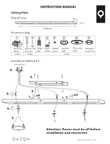
Standard Mounting (Figure 1)
hangs from the ceiling by a connec-
tor pipe (included), for ceilings 2.3
m or higher. For ceilings higher than
2.3 m.
Figure 1 - Standard MountingFigure 1 - Standard Mounting
Figure 1 - Standard MountingFigure 1 - Standard Mounting
Figure 1 - Standard Mounting
30.5 cm

7
41509-01 12/19/2005
®
STEP 2 - ASSEMBLING THE FANSTEP 2 - ASSEMBLING THE FAN
STEP 2 - ASSEMBLING THE FANSTEP 2 - ASSEMBLING THE FAN
STEP 2 - ASSEMBLING THE FAN
1. Feed the wires and the steel
cable support from the fan
through the canopy and the pipe.
2. Screw pipe into fan assembly un-
til tight. IMPORTANT! Tighten pipe
setscrew as shown in Figure 3.
CAUTION CAUTION
CAUTION CAUTION
CAUTION
• The pipe adapter has a
special coating on the
threads. Do not remove
this coating; the coating
prevents the pipe from
unscrewing. Once as-
sembled, do not remove
the pipe.
WARNING WARNING
WARNING WARNING
WARNING
• Failure to complete the
steps above properly
could result in the fan
falling.
Figure 3 - Assembling The FanFigure 3 - Assembling The Fan
Figure 3 - Assembling The FanFigure 3 - Assembling The Fan
Figure 3 - Assembling The Fan
Pipe Setscrew

8
41509-01 12/19/2005
®
STEP 3 - HANGING THE FANSTEP 3 - HANGING THE FAN
STEP 3 - HANGING THE FANSTEP 3 - HANGING THE FAN
STEP 3 - HANGING THE FAN
Hang fan from the previously in-
stalled J-Hook or U-Hook.
SECURING FAN TO SECONDARYSECURING FAN TO SECONDARY
SECURING FAN TO SECONDARYSECURING FAN TO SECONDARY
SECURING FAN TO SECONDARY
SUPPORTSUPPORT
SUPPORTSUPPORT
SUPPORT
1. Find the looped end of the
braided cable and insert it
through the ceiling plate and
one of the holes in the outlet
box into the ceiling.
2. Access the support brace in the
ceiling. You may not be able
to do this from below the ceil-
ing depending on your instal-
lation site.
3. Drive a #10 x 38 mm (1-1/2")
wood screw and washer into
the side of the brace that holds
the outlet box. Leave 3 mm (1/
8") of space between the sup-
port brace and the washer.
Figure 4a - Installing the Wood ScrewFigure 4a - Installing the Wood Screw
Figure 4a - Installing the Wood ScrewFigure 4a - Installing the Wood Screw
Figure 4a - Installing the Wood Screw
into the Braceinto the Brace
into the Braceinto the Brace
into the Brace
Figure 4b - Hooking the CableFigure 4b - Hooking the Cable
Figure 4b - Hooking the CableFigure 4b - Hooking the Cable
Figure 4b - Hooking the Cable
Figure 4c - Tightening the LoopFigure 4c - Tightening the Loop
Figure 4c - Tightening the LoopFigure 4c - Tightening the Loop
Figure 4c - Tightening the Loop
4. Wrap the braided cable around
the support brace once creat-
ing a complete circle.
5. Hook the looped end of the
cable over the wood screw so
that the braided cable lies be-
tween the washer and the sup-
port brace.
6. Tighten the loop and secure the
screw and washer all the way
down to the support brace.
7. Coil up the excess cable. Return
to the fan to complete instal-
lation.

9
41509-01 12/19/2005
®
Figure 5 - Wiring DiagramFigure 5 - Wiring Diagram
Figure 5 - Wiring DiagramFigure 5 - Wiring Diagram
Figure 5 - Wiring Diagram
Earth
Ceiling
Blue
Brown
Blue
Black/White
1
2
Brown
Separate Control of Light Kit
Wire from Hanger
From Fan
switch.)
Connect Blk/Wht Wire from fan
to Wall Switch Wire for separate
Connect Blk/Wht Wire from fan
is no separate Wall Switch Wire
for the light kit.
1
2

10
41509-01 12/19/2005
®
Figure 5 - Wiring DiagramFigure 5 - Wiring Diagram
Figure 5 - Wiring DiagramFigure 5 - Wiring Diagram
Figure 5 - Wiring Diagram
Earth
Power
Wires
In
Ceiling
Blue
Brown
Blue
Black/White
1
2
Connections:
Brown
(Optional Line)
Wall Switch Wire For
Separate Control of Light Kit
Green/Yellow
Wire from Hanger
3 Wires
From Fan
(Note: Wall switch
must be acceptable
as a general-use
switch.)
Connect Blk/Wht Wire from fan
to Wall Switch Wire for separate
control of light, or
Connect Blk/Wht Wire from fan
to Ceiling Brown Wire if there
is no separate Wall Switch Wire
for the light kit.
1
2

11
41509-01 12/19/2005
®
STEP 5 - INSTSTEP 5 - INST
STEP 5 - INSTSTEP 5 - INST
STEP 5 - INST
ALLING THE CANOPYALLING THE CANOPY
ALLING THE CANOPYALLING THE CANOPY
ALLING THE CANOPY
Figure 6 - Assembling the CanopyFigure 6 - Assembling the Canopy
Figure 6 - Assembling the CanopyFigure 6 - Assembling the Canopy
Figure 6 - Assembling the Canopy
1. Slide the canopy to where the
top is within 2 mm of the ceil-
ing. The canopy should not
touch the ceiling or it will cause
noise and possible wobble.
2. Insert and tighten the #6-32
canopy screw to hold the canopy
in place. Refer to Figure 6.
Note:Note:
Note:Note:
Note: Two screws and screw
holes are provided and may be
used to better level the canopy.
Canopy
Screw
Canopy

12
41509-01 12/19/2005
®
Figure 7a - Inserting Grommet intoFigure 7a - Inserting Grommet into
Figure 7a - Inserting Grommet intoFigure 7a - Inserting Grommet into
Figure 7a - Inserting Grommet into
Fan BladeFan Blade
Fan BladeFan Blade
Fan Blade
Figure 7b - Attaching Fan Blade toFigure 7b - Attaching Fan Blade to
Figure 7b - Attaching Fan Blade toFigure 7b - Attaching Fan Blade to
Figure 7b - Attaching Fan Blade to
Blade IrBlade Ir
Blade IrBlade Ir
Blade Ir
onon
onon
on
Figure 7c - Attaching Fan Blade toFigure 7c - Attaching Fan Blade to
Figure 7c - Attaching Fan Blade toFigure 7c - Attaching Fan Blade to
Figure 7c - Attaching Fan Blade to
Blade IrBlade Ir
Blade IrBlade Ir
Blade Ir
on using Decorative Medal-on using Decorative Medal-
on using Decorative Medal-on using Decorative Medal-
on using Decorative Medal-
lionlion
lionlion
lion
feature a decorative medallion
as well as a blade iron. Insert
the assembly screws into the
blade iron, through the blade
and into the medallion, with the
blade sandwiched between the
blade iron and medallion as
shown in Figure 7c.
Hunter fans use several styles of
fan blade irons (brackets that hold
the blade to the fan).
1. Your fan may include blade
grommets. If your fan has grom-
mets, insert them by hand into
the holes as shown in Figure 7a.
2. Attach each blade to blade iron
using three blade assembly screws
as shown in Figure 7b. Some fans
STEP 6 - ASSEMBLING FAN BLADESSTEP 6 - ASSEMBLING FAN BLADES
STEP 6 - ASSEMBLING FAN BLADESSTEP 6 - ASSEMBLING FAN BLADES
STEP 6 - ASSEMBLING FAN BLADES
If you used grommets, the
blades may appear slightly loose
after screws are tightened. This
is normal.
3. Remove the blade mounting
screws and rubber shipping
bumpers from the motor.
Grommet
Fan
Blade
Medallion
Blade
Iron
continued

13
41509-01 12/19/2005
®
4. For each blade, insert one blade
mounting screw through the
blade iron as shown in Figure 7d,
and attach lightly to the fan. In-
sert the second blade mounting
screw, then securely tighten both
mounting screws.
Figure 7d - Attaching Blade Irons toFigure 7d - Attaching Blade Irons to
Figure 7d - Attaching Blade Irons toFigure 7d - Attaching Blade Irons to
Figure 7d - Attaching Blade Irons to
Hub of Fan AssemblyHub of Fan Assembly
Hub of Fan AssemblyHub of Fan Assembly
Hub of Fan Assembly

14
41509-01 12/19/2005
®
STEP 7 - ATTSTEP 7 - ATT
STEP 7 - ATTSTEP 7 - ATT
STEP 7 - ATT
ACHING THE SWITCH HOUSINGACHING THE SWITCH HOUSING
ACHING THE SWITCH HOUSINGACHING THE SWITCH HOUSING
ACHING THE SWITCH HOUSING
Figure 8a - Attaching Upper SwitchFigure 8a - Attaching Upper Switch
Figure 8a - Attaching Upper SwitchFigure 8a - Attaching Upper Switch
Figure 8a - Attaching Upper Switch
Housing to Switch Housing Mount-Housing to Switch Housing Mount-
Housing to Switch Housing Mount-Housing to Switch Housing Mount-
Housing to Switch Housing Mount-
ing Plateing Plate
ing Plateing Plate
ing Plate
Housing
Assembly
Screw
Switch
Housing
Mounting
Plate
Upper Plug
Connector
Upper
Switch
Housing
Figure 8b - Mounting the UpperFigure 8b - Mounting the Upper
Figure 8b - Mounting the UpperFigure 8b - Mounting the Upper
Figure 8b - Mounting the Upper
Switch HousingSwitch Housing
Switch HousingSwitch Housing
Switch Housing
The switch housing is made up of
two sections: the upper switch
housing and the lower switch hous-
ing.
AA
AA
A
TTTT
TTTT
TT
ACHING THE UPPER SWITCHACHING THE UPPER SWITCH
ACHING THE UPPER SWITCHACHING THE UPPER SWITCH
ACHING THE UPPER SWITCH
HOUSINGHOUSING
HOUSINGHOUSING
HOUSING
1. Partially install two #6-32 x 3/8"
housing assembly screws into the
switch housing mounting plate as
shown in Figure 8a.
2. Feed the upper plug connector
through the center opening of
the upper switch housing. See
Figure 8a.
3. Align the keyhole slots in the up-
per switch housing with the hous-
ing assembly screws installed in
sub-step 1.
4. Turn the upper switch housing
counterclockwise until the hous-
ing assembly screws are firmly
situated in the narrow end of the
keyhole slots as shown in Figure
8b. Install the one remaining #6-
32 x 3/8" housing assembly screw
into the third hole in the upper
switch housing. Tighten all three
screws firmly.
CAUTION CAUTION
CAUTION CAUTION
CAUTION
Make sure the upper switch
housing is securely attached to
the switch housing mounting
plate. Failure to properly at-
tach and tighten all three hous-
ing assembly screws could re-
sult in the switch housing and
light fixture falling.
continued

15
41509-01 12/19/2005
®
STEP 8 - INSTSTEP 8 - INST
STEP 8 - INSTSTEP 8 - INST
STEP 8 - INST
ALLING ACCESSORALLING ACCESSOR
ALLING ACCESSORALLING ACCESSOR
ALLING ACCESSOR
Y LIGHT FIXTURESY LIGHT FIXTURES
Y LIGHT FIXTURESY LIGHT FIXTURES
Y LIGHT FIXTURES
Figure 9 - Removing Plug Button andFigure 9 - Removing Plug Button and
Figure 9 - Removing Plug Button andFigure 9 - Removing Plug Button and
Figure 9 - Removing Plug Button and
Switch Housing CapSwitch Housing Cap
Switch Housing CapSwitch Housing Cap
Switch Housing Cap
Lower
Switch
Housing
Plug Button
If you are installing an accessory
light xture, remove the plug but-
ton, the switch housing cap, and
the lower switch housing as shown
in Figure 9.
To install the light kit, follow the
instructions included with the light
kit for wiring, mounting, and as-
sembly. After completing the light
kit installation, follow sub-steps
Switch
Housing
Cap
GNINRAW GNINRAW
GNINRAW GNINRAW
• To avoid possible electri-
cal shock, before wiring
fan, disconnect power
by turning o the circuit
breakers both to the out-
let box and to its associ-
ated wall switch loca-
tion. If you cannot lock
the circuit breakers in
the o position, se-
curely fasten a promi-
nent warning device,
such as a tag, to the ser-
vice panel.
• All wiring must be in ac-
cordance with national
and local electrical
codes. If you are unfa-
miliar with wiring, you
should use a qualied
electrician.
1 and 2 of Step 8 - ATTACHING THE
SWITCH HOUSING, to reattach the
lower switch housing.
If you are not installing a light x-
ture, turn to OPERATING YOUR
HUNTER FAN for additional in-
structions.
• Connect house wiring
to the fan before at-
taching the light x-
ture to the fan.

16
41509-01 12/19/2005
®
STEP 8 - INSTSTEP 8 - INST
STEP 8 - INSTSTEP 8 - INST
STEP 8 - INST
ALLING ACCESSORALLING ACCESSOR
ALLING ACCESSORALLING ACCESSOR
ALLING ACCESSOR
Y LIGHT FIXTURESY LIGHT FIXTURES
Y LIGHT FIXTURESY LIGHT FIXTURES
Y LIGHT FIXTURES
Figure 9 - Removing Plug Button andFigure 9 - Removing Plug Button and
Figure 9 - Removing Plug Button andFigure 9 - Removing Plug Button and
Figure 9 - Removing Plug Button and
Switch Housing CapSwitch Housing Cap
Switch Housing CapSwitch Housing Cap
Switch Housing Cap
Lower
Switch
Housing
Plug Button
If you are installing an accessory
light fixture, remove the plug but-
ton, the switch housing cap, and
the lower switch housing as shown
in Figure 9.
To install the light kit, follow the
instructions included with the light
kit for wiring, mounting, and as-
sembly. After completing the light
kit installation, follow sub-steps
Switch
Housing
Cap
WARNING WARNING
WARNING WARNING
WARNING
• To avoid possible electri-
cal shock, before wiring
fan, disconnect power
by turning off the circuit
breakers both to the out-
let box and to its associ-
ated wall switch loca-
tion. If you cannot lock
the circuit breakers in
the off position, se-
curely fasten a promi-
nent warning device,
such as a tag, to the ser-
vice panel.
• All wiring must be in ac-
cordance with national
and local electrical
codes. If you are unfa-
miliar with wiring, you
should use a qualified
electrician.
• All wiring must be in ac-
cordance with national
and local electrical
codes. If you are unfa-
miliar with wiring, you
should use a qualified
electrician.
1 and 2 of Step 8 - ATTACHING THE
SWITCH HOUSING, to reattach the
lower switch housing.
If you are not installing a light fix-
ture, turn to OPERATING YOUR
HUNTER FAN for additional in-
structions.
• Connect house wiring
to the fan before at-
taching the light fix-
ture to the fan.

17
41509-01 12/19/2005
®
3. Ceiling fans work best by blow-
ing air downward (counterclock-
wise blade rotation) in warm
weather to cool the room with a
direct breeze. In winter, having
the fan draw air upward (clock-
wise blade rotation) will distrib-
ute the warmer air trapped at
the ceiling around the room with-
out causing a draft.
OPERAOPERA
OPERAOPERA
OPERA
TING YOUR HUNTER FANTING YOUR HUNTER FAN
TING YOUR HUNTER FANTING YOUR HUNTER FAN
TING YOUR HUNTER FAN
Control switches are identified by the
following symbols:
Figure 10b - Air Flow PatternsFigure 10b - Air Flow Patterns
Figure 10b - Air Flow PatternsFigure 10b - Air Flow Patterns
Figure 10b - Air Flow Patterns
To change the direction of air
flow, turn the fan off and let it
come to a complete stop. Slide
the reversing switch on the fan
to the opposite position as shown
in Figure 10c. Restart fan.
4. If your fan wobbles when oper-
ating, use the enclosed balancing
kit and instructions to balance the fan.
Pull
Chain
Reversing
Switch
Figure 10c - Pull Chain and ReversingFigure 10c - Pull Chain and Reversing
Figure 10c - Pull Chain and ReversingFigure 10c - Pull Chain and Reversing
Figure 10c - Pull Chain and Reversing
SwitchSwitch
SwitchSwitch
Switch
1. Turn on electrical power to the
fan.
2. The pull chain controls power to
the fan. The chain has four set-
tings in sequence: High, Medium,
Low and Off.
• Pull the chain slowly to change
settings.
• Release slowly to prevent the
chain from recoiling into the
blades.
Figure 10a - Control SymbolsFigure 10a - Control Symbols
Figure 10a - Control SymbolsFigure 10a - Control Symbols
Figure 10a - Control Symbols
Fan Reversing

18
41509-01 12/19/2005
®
CLEANING AND MAINTENANCECLEANING AND MAINTENANCE
CLEANING AND MAINTENANCECLEANING AND MAINTENANCE
CLEANING AND MAINTENANCE
Caring for blades: Wood finish
blades should be cleaned with a fur-
niture polishing cloth. Occasionally,
a light coat of furniture polish may
be applied for added protection and
beauty. Painted and high-gloss
blades may be cleaned in the same
manner as the fan finish.
If you need parts or service assistance
contact your Hunter Fan retailer or
visit our WEB site at:
http://www.hunterfan.com
Caring for finishes: For cleaning, a
soft brush or lint-free cloth should
be used to prevent scratching the fin-
ish. A vacuum cleaner brush nozzle
can remove heavier dust. Surface
smudges or an accumulation of dirt
and dust can easily be removed by
using a mild detergent and a slightly
dampened cloth. An artistic agent
may be used, but never use abrasive
cleaning agents as they will damage
the finish.

19
41509-01 12/19/2005
®
TROUBLESHOOTINGTROUBLESHOOTING
TROUBLESHOOTINGTROUBLESHOOTING
TROUBLESHOOTING
Nothing happens; fan does not move.
Noisy operation.
1. Power turned off, fuse blown, or
circuit breaker tripped.
2. Loose wire connections or wrong
connections.
3. Motor reversing switch not en-
gaged.
4. Pull chain switch not “on.”
5. Shipping bumpers still in place.
1. Blade brackets screwed loosely to
motor.
2. Blade screwed loosely to blade iron.
3. Blade cracked.
PROBLEMPROBLEM
PROBLEMPROBLEM
PROBLEM
PROBABLE CAUSEPROBABLE CAUSE
PROBABLE CAUSEPROBABLE CAUSE
PROBABLE CAUSE
SOLUTIONSOLUTION
SOLUTIONSOLUTION
SOLUTION
1. Turn power on, replace fuse, or re-
set breaker.
2a.Loosen canopy, check all connec-
tions according to STEP 5 - WIR-
ING THE FAN (turn power off
before checking).
2b.Check the plug connection in the
switch housing according to STEP
8 - ATTACHING THE SWITCH
HOUSING.
3. Push switch firmly up or down.
4. Pull switch chain.
5. Remove shipping bumpers.
1. Tighten screws until snug.
2. Tighten screws until snug.
3. Replace all blades.

20
41509-01 12/19/2005
®
PROBLEMPROBLEM
PROBLEMPROBLEM
PROBLEM
PROBABLE CAUSEPROBABLE CAUSE
PROBABLE CAUSEPROBABLE CAUSE
PROBABLE CAUSE
SOLUTIONSOLUTION
SOLUTIONSOLUTION
SOLUTION
Noisy operation (continued).
Excessive wobbling.
Note: When switching from medium
to low speed, you may notice some fan
wobble. When the fan stabilizes at low
speed, wobble will disappear.
4. Using non-approved speed control.
5. Glass screwed loosely to fix-
ture.
6. Switch housing is loose.
1. Unbalanced blades.
2. Loose blades or blade irons.
3. Fan not secure on hanger as-
sembly.
4. Fan hanger ball not seated in
Hanger Bracket.
4. Change to approved speed control.
5. Hand-tighten the light fixture
screws. Ensure that rubber noise
isolators are installed.
6. Check and tighten screws to the
switch housing mounting plate and
to the upper and lower switch
housing.
1. Use balancing kit included with fan.
2. Tighten all screws.
3. Turn power off, support fan very
carefully, loosen canopy and hang
correctly.
4. Turn power off, support the fan
very carefully, and check that the
hanger ball is properly seated.
If you have tried these troubleshooting solutions and still have trouble visit our Web site at http://www.hunterfan.com.
/