Page is loading ...

INS #
Brand Logo
reversed out of
black
INS #
IB5060 01EN
Installation Instructions - Galleon LED Wall Mounted Luminiare
WARNINGWARNING
DISCLAIMER OF LIABILITY: Cooper Lighting Solutions assumes no liability for damages or losses of any kind
that may arise from the improper, careless, or negligent installation, handling or use of this product.
NOTICE: Green ground wire provided in proper location. Do not relocate.
ATTENTION Receiving Department: Note actual fixture description of any shortage or noticeable damage on
delivery receipt. File claim for common carrier (LTL) directly with carrier. Claims for concealed damage must be
filed within 15 days of delivery. All damaged material, complete with original packing must be retained.
Safety: This fixture must be wired in accordance with the National Electrical Code and applicable local codes and
ordinances. Proper grounding is required to insure personal safety. Carefully observe grounding procedure under
installation section.
APPLICATIONS: This lighting fixture is designed for outdoor lighting services, and should not be used in area
of limited ventilation or inside high ambient temperature enclosures. It must be stored in a dry location prior to
installation. Do not expose lighting fixture to rain, dust or other environmental conditions prior to installation
and insertion of photo control or shorting cap (if so equipped). Best results will be obtained if installed and
maintained according to the following recommendations.
Risk of Fire, Electrical Shock, Cuts or other Casualty Hazards- Installation and maintenance of this
product must be performed by a qualified electrician. This product must be installed in accordance
with the applicable installation code by a person familiar with the construction and operation of the
product and hazards involved.
Risk of Fire and Electric Shock- Make certain power is OFF before starting installation or attempting
any maintenance. Disconnect power at fuse or circuit breaker.
Risk of Fire- Refer to product label for specific minimum supply conductor requirements.
Risk of Burn- Disconnect power and allow fixture to cool before handling or servicing.
Risk of Personal Injury- Fixture may become damaged and/or unstable if not installed properly.
Failure to comply with these instructions may result in death, serious bodily injury and property damage.

2
Cooper Lighting Solutions IB506001EN Installation Instructions
Installation Instructions - Galleon LED Wall Mounted Luminiare
INSTALLATION
ote: N Care must be taken not to set lighting fixture down
on optical lenses or lift the fixture in the lens area.
ote: N Do not attempt to mount this luminaire by drilling
holes through the luminaire back wall. Modifying the
housing will void warranty terms and conditions.
Tools Required
Ratchet, a 3/4” socket; #2 Phillips head screw driver;
3/16” allen key; torque wrench ; drill with 7/16 bit.
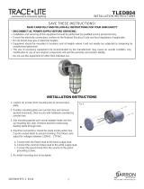
Wall Mount - Standard (Figure 1) For use in down
lighting application only
1. Remove the mounting plate from the fixture by
loosening the set screws using 3/16” allen key.
2. Loosen the lock nut from the mounting plate and
detach tether.
3. Mount the mounting plate to the junction box or wall
with gasket against wall and secure to the structure
with fasteners (by others). Tighten fasteners to
20 in-lbs.
ote: N Mounting plate must be in the upright position as
specified by the label.
4. Pull fixture wires carefully from fixture.
ote: N Ensure wire plug at the bottom of luminaire is in
place properly.
5. Connect the supply wires to appropriate luminaire
leads.
●
Supply side ground wire to ground luminaire lead.
●
Supply side neutral wire to white luminaire lead.
●
Supply side line voltage wire to black luminaire lead.
6. Reattach tether to the mounting plate.
7. Tighten the lock nut.
ote: N Tether must be able to rotate freely; therefore do not
over tighten lock nut. Fixture must hang from tether,
NOT from electrical wires.
8. Slide the luminaire mounting bracket over the top lip
of the wall mounting plate to hang the luminaire. Hold
luminaire in place while allowing the back surface of
luminaire to rest against wall.
9. Allen head screws must be captured behind lower
beveled edge of mounting plate to ensure luminaire
is secure. Press luminaire firmly against wall and
re-tighten the two (2) set screws to secure the
luminaire to the mounting plate.
Figure 1.
Wiring Grommet
Retaining Plate
Lock Nut
Mounting Plate
(Secure To J-Box Or Wall)
Tether
Mounting Gasket
Junction Box
Or Wall
Allen Head
Screws (2)

3
Cooper Lighting Solutions IB506001EN Installation instructions
Installation Instructions - Galleon LED Wall Mounted Luminiare
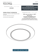
Pole Mount - Quick connect arm option
(Figure 2. – Figure 4.)
1. Pole mounting arm is designed for a square or round
pole. Round pole installation will require the mounting
arm break away tabs to be removed (Figure 2). Grab
break away tab with pliers and break-away the tabs.
2. Mount the arm to the round or square pole using the
provided ½” x 1-3/4” long bolts and nuts. Torque bolts
to 40 ft lbs (55 Nm).
3. Hold fixture wires tightly against the mounting arm
while guiding fixture’s house-sided arm onto pole
mounting arm (Figure 4). Tighten the center Philips
head screw to 20 in-lbs (2.3 N-M).
4. Make wire connections inside the mounting arm. Refer
to wire diagram for power connections
(Figure 3). Connect the supply wires to appropriate
luminaire leads.
●
Supply ground wire to ground luminaire lead.
●
Supply neutral wire to white luminaire lead.
●
Supply line voltage wire to black luminaire lead.
5. Install pole mounting arm cover and tighten Philips
head screws to 20 in-lbs (2.3 N-M) (Figure 4).
ote: N Ensure the luminaire supply leads do not get pinched
between cover and mounting arm.
6. Install pole cap after completion of luminaire installation
and wiring.
Figure 2.
Figure 3.
Figure 4.
Line (Black)
Black
White (Black 480V)
Green Ground
Fixture
White Common
(Black 480V)
Green Ground
Pole Mounting Arm
Pole Mounting
Arm Cover
Philips Head
Screws
Pole
Mounting Arm
House Sided Arm
For Round Pole
Installations
Break Off Tab’s
For Round Pole
Installations
Break Off Tab’s

4
Cooper Lighting Solutions IB506001EN Installation Instructions
Installation Instructions - Galleon LED Wall Mounted Luminiare
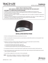
Figure 5.
Figure 6.
Figure 7.
Line (Black)
Black
White (Black 480V)
Green Ground
Fixture
White Common
(Black 480V)
Green Ground
3/8” Carriage Bolt
3/8” Carriage Nut
Pole Mount - Mast arm option (Figure 5. - Figure 7.)
1. Slip the assembly over the mast arm (Figure 5).
ote: N Ensure the wires do not get pinched and the mast
arm is fully seated into the mast arm adapter as it
should bottom out against the adapter.
2. Secure the mast arm to the pole with the four
3/8-16 x 3/8” set screws and tighten to 120 in lbs.
3. Drill a 7/16” hole through the mast arm and install the
3/8” carriage bolt and nut and tighten to 200 in lbs.
(Figure 6).
3/8-16 X 3/8” Set Screws
3/8-16 X 3/8” Set Screws
Use care when drilling this hole so as not to damage any
wires within the mast arm.
4. Make wire connections inside the mounting arm. Refer
to wire diagram for power connections
(Figure 7). Connect the supply wires to appropriate
luminaire leads.
●
Supply ground wire to ground luminaire lead.
●
Supply neutral wire to white luminaire lead.
●
Supply line voltage wire to black luminaire lead.

5
Cooper Lighting Solutions IB506001EN Installation instructions
Installation Instructions - Galleon LED Wall Mounted Luminiare
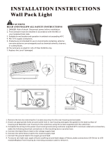
Wall Mount – Battery back box emergency option
(Figure 8.) For use in down light application only
ote: N Unit with back box weighs more than 25 lbs.,
connect the mounting plate to the wall using the 4
largest holes and appropriate anchors/hardware (not
provided).
1. Remove the mounting plate from the back of the back
box by loosening two allen heads screws.
2. Mount the mounting plate to the wall using four larger
holes with appropriate hardware (by others). Plate must
be in the correct upright position per the label.
3. Connect the supply wires out of the wall to appropriate
luminaire leads out of the back box.
●
Supply ground wire to ground luminaire lead.
●
Supply neutral wire to white luminaire lead.
●
Supply line voltage wire to black luminaire lead.
ote: N The luminaire with back box assembly attached
weighs over 25 lbs handle with appropriate safety
measures.
4. Slide the back box mounting bracket over the lip of the
mounting plate.
ote: N Ensure the luminaire supply leads out of the back
box do not get pinched.
5. Re tighten the two Allen head screws to secure the
luminaire with back box assembly to the mounting
plate.
6. Remove back box access door by loosening four
screws.
7. Find the battery connector for battery pack and connect
the male and female ends.
8. Retighten the four screws to attach the access cover
back in place.
Figure 8.
GWC Fixture
Allen Head Screws
Wall
Backbox Access Plate
GWC Fixture
Top Lip of Mounting Plate
Mounting Bracket
Wall mounting plate
Backbox
Gasket on Back
(4) Larger Holes
Backbox

Cooper Lighting Solutions
1121 Highway 74 South
Peachtree City, GA 30269
P: 770-486-4800
www.cooperlighting.com
Canada Sales
5925 McLaughlin Road
Mississauga, Ontario L5R 1B8
P: 905-501-3000
F: 905-501-3172
© 2020 Cooper Lighting Solutions
All Rights Reserved
Printed in USA
Imprimé aux États-Unis
Impreso en los EE. UU.
Publication No. IB506001EN
March 11, 2020
Cooper Lighting Solutions is a
registered trademark.
All trademarks are property
of their respective owners.
Cooper Lighting Solutions est une
marque de commerce
déposée. Toutes les autres marques
de commerce sont la propriété de leur
propriétaire respectif.
Cooper Lighting Solutions es una
marca comercial
registrada. Todas las marcas
comerciales son propiedad de sus
respectivos propietarios.
Product availability, specifications,
and compliances are subject to
change without notice.
La disponibilité du produit, les
spécifications et les conformités
peuvent être modifiées sans préavis.
La disponibilidad de productos, las
especificaciones y los cumplimientos
están sujetos a cambio sin previo
aviso.
Warranties and Limitation of Liability
Please refer to www.cooperlighting.com/LightingWarrantyTerms for our terms and conditions.
Garanties et limitation de responsabilité
Veuillez consulter le site www.cooperlighting.com/LightingWarrantyTerms pour obtenir les conditions générales.
Garantías y Limitación de Responsabilidad
Visite www.cooperlighting.com/LightingWarrantyTerms para conocer nuestros términos y condiciones.
FCC Statement
Note: This equipment has been tested and found to comply with the
limits for a Class A digital device, pursuant to part 15 of the FCC Rules.
These limits are designed to provide reasonable protection against
harmful interference when the equipment is operated in a commercial
environment. This equipment generates, uses, and can radiate radio
frequency energy and, if not installed and used in accordance with
the instruction manual, may cause harmful interference to radio
communications. Operation of this equipment in a residential area
is likely to cause harmful interference in which case the user will be
required to correct the interference at his own expense.
Declaración de la FCC
Nota: Este equipo ha sido probado y cumple con los límites para un
dispositivo digital de Clase A, de conformidad con la parte 15 de las
Normas de la FCC. Estos límites están diseñados para proporcionar
una protección razonable contra interferencias perjudiciales cuando el
equipo se opera en un entorno comercial. Este equipo genera, utiliza y
puede emitir energía de radiofrecuencia y, si no se instala y utiliza de
acuerdo con el manual de instrucciones, puede causar interferencias
perjudiciales en las comunicaciones de radio. El funcionamiento
de este equipo en un área residencial puede causar interferencias
perjudiciales, en cuyo caso el usuario deberá corregir las interferencias
por su cuenta.
/