Page is loading ...

INVERTER
INVERTER A800
FR-A802-P INSTRUCTION MANUAL (HARDWARE)
C
INTRODUCTION
1
INSTALLATION AND WIRING
2
PRECAUTIONS FOR USE OF
THE INVERTER
3
PROTECTIVE FUNCTIONS
4
PRECAUTIONS FOR
MAINTENANCE AND
INSPECTION
5
SPECIFICATIONS
6
IB(NA)-0600651ENG-C(2010)MEE Printed in Japan Specifications subject to change without notice.
A800
FR-A802-P
(SEPARATED CONVERTER TYPE FOR PARALLEL OPERATION)
INSTRUCTION MANUAL (HARDWARE)
FR-A842-09620(400K) to 12120(500K)-P
High functionality and high performance
HEAD OFFICE: TOKYO BUILDING 2-7-3, MARUNOUCHI, CHIYODA-KU, TOKYO 100-8310, JAPAN

Safety instructions
1
Thank you for choosing Mitsubishi Electric inverter.
This Instruction Manual describes handling and cautions about the hardware, such as installation and wiring, for the FR-A802-P
(separated converter type for parallel operation) inverter that are different from the FR-A800.
Information about the software, such as basic operations and parameters, is described in the Instruction Manual (Detailed) of the
FR-A800 in the CD-ROM enclosed with the product. For information about the parameters and restrictions on the parallel operation
specifications, refer to the Parallel Operation Function Manual in the enclosed CD-ROM. In addition to this manual, read all the rel-
evant instruction manuals on the enclosed CD-ROM carefully to ensure proper use. Do not use this product until you have a full
knowledge of this product's workings, safety information and instructions.
Please forward this Instruction Manual to the end user.
Electric shock prevention
Fire prevention
Injury prevention
Additional instructions
The following instructions must be also followed. If this product
is handled incorrectly, it may cause unexpected fault, an injury,
or an electric shock.
Safety instructions
Do not attempt to install, operate, maintain or inspect this
product until you have read the Instruction Manuals and
appended documents carefully. Do not use this product until
you have a full knowledge of this product mechanism, safety
information and instructions.
Installation, operation, maintenance and inspection must be
performed by qualified personnel. Here, qualified personnel
means a person who meets all the following conditions:
• A person who possesses a certification in regard with elec-
tric appliance handling, or person took a proper engineering
training. Such training may be available at your local Mitsubi-
shi Electric office. Contact your local sales office for sched-
ules and locations.
• A person who can access operating manuals for the protec-
tive devices (for example, light curtain) connected to the
safety control system, or a person who has read these manu-
als thoroughly and familiarized themselves with the protective
devices.
In this Instruction Manual, the safety instruction levels are
classified into "WARNING" and "CAUTION".
Incorrect handling may cause hazard-
ous conditions, resulting in death or
severe injury.
Incorrect handling may cause hazard-
ous conditions, resulting in medium
or slight injury, or may cause only
material damage.
Note that even the level may lead to a
serious consequence depending on conditions. Be sure to fol-
low the instructions of both levels as they are critical to per-
sonnel safety.
WARNING
Do not remove the front cover or the wiring cover while the power
of this product is ON, and do not run the inverter with the front
cover or the wiring cover removed as the exposed high voltage
terminals or the charging part of the circuitry can be touched.
Otherwise you may get an electric shock.
Even if power is OFF, do not remove the front cover except for
wiring or periodic inspection as the inside of this product is
charged. Otherwise you may get an electric shock.
Before wiring or inspection, check that the LED display of the
operation panel is OFF. Any person who is involved in wiring or
inspection shall wait for 10 minutes or longer after the power
supply has been cut off, and check that there are no residual
voltage using a tester or the like. The capacitor is charged with
high voltage for some time after power OFF, and it is dangerous.
This product must be earthed (grounded). Earthing (grounding)
must conform to the requirements of national and local safety
regulations and electrical code (NEC section 250, IEC 61140
class 1 and other applicable standards). A neutral-point earthed
(grounded) power supply must be used to be compliant with EN
standard.
Any person who is involved in wiring or inspection of this product
shall be fully competent to do the work.
This product body must be installed before wiring. Otherwise you
may get an electric shock or be injured.
Do not touch the setting dial or keys with wet hands. Doing so
may cause an electric shock.
Do not subject the cables to scratches, excessive stress, heavy
loads or pinching. Doing so may cause an electric shock.
Do not change the cooling fan while power is ON as it is
dangerous.
Do not touch the printed circuit board or handle the cables with
wet hands. Doing so may cause an electric shock.
WARNING
CAUTION
CAUTION
CAUTION
This product must be installed on a nonflammable wall without
any through holes so that nobody touches the heat sink, etc. on
the rear side of this product. Installing it on or near flammable
material may cause a fire.
If this product has become faulty, the product power must be
switched OFF. A continuous flow of large current may cause a
fire.
Be sure to perform daily and periodic inspections as specified in
the Instruction Manual. If this product is used without any
inspection, a burst, breakage, or a fire may occur.
CAUTION
The voltage applied to each terminal must be as specified in the
Instruction Manual. Otherwise burst, damage, etc. may occur.
The cables must be connected to the correct terminals.
Otherwise burst, damage, etc. may occur.
The polarity (+ and -) must be correct. Otherwise burst, damage,
etc. may occur.
While power is ON or for some time after power-OFF, do not
touch this product as it will be extremely hot. Doing so may
cause a burn.
CAUTION
Transportation and installation
Any person who is opening a package using a sharp object, such
as a knife or cutter, must wear gloves to prevent injuries caused
by the edge of the sharp object.
This product must be transported in correct method that
corresponds to the weight. Failure to do so may lead to injuries.
Do not stand or place any heavy object on this product.
Do not stack the boxes containing this product higher than the
number recommended.
When carrying this product, do not hold it by the front cover.
Doing so may cause a fall or failure of the product.
During installation, caution must be taken not to drop this product
as doing so may cause injuries.
This product must be installed on the surface that withstands the
weight of the product.
Do not install this product on a hot surface.
The installing orientation of this product must be correct.
This product must be installed on a strong surface securely with
screws so that it does not drop.
Do not install or operate this product if it is damaged or has parts
missing.
Foreign conductive objects must be prevented from entering this
product. That includes screws and metal fragments or other
flammable substance such as oil.
As this product is a precision instrument, do not drop or subject it
to impact.
The surrounding air temperature must be between -10 and
+50°C (non-freezing). Otherwise the product may be damaged.
The ambient humidity must be 95% RH or less (non-condensing)
for this product. Otherwise the product may be damaged. (Refer
to page 18 for details.)

2
Safety instructions
CAUTION
Transportation and installation
The temporary storage temperature (applicable to a short limited
time such as a transportation time) must be between -20 and
+65°C. Otherwise this product may be damaged.
This product must be used indoors (without corrosive gas,
flammable gas, oil mist, dust and dirt). Otherwise the product
may be damaged.
Do not use this product at an altitude above 2500 m. Vibration
should not exceed 2.9 m/s
2
at 10 to 55 Hz in X, Y, and Z
directions. Otherwise the product may be damaged. (For the
installation at an altitude above 1000 m, consider a 3% reduction
in the rated current per 500 m increase in altitude.) (Refer to
page 18 for details.)
If halogens (including fluorine, chlorine, bromine, and iodine)
contained in fumigants for wood packages enter this product, the
product may be damaged. Prevent the entry of fumigant
residuals or use an alternative method such as heat disinfection.
Note that sterilization or disinfection of wood packages should be
performed before packing the product.
Wiring
Do not install a power factor correction capacitor, surge absorber,
or radio noise filter on the output side of this product. Doing so
may be overheated or burn out.
The output of this product (output terminals U, V, W) must be
correctly connected to a motor. Otherwise the motor rotates
inversely.
Test operation
Before starting the test operation, confirm or adjust the
parameter settings. Failure to do so may cause some machines
to make unexpected motions.
WARNING
Usage
Depending on the function settings of this product, the product
does not stop its output even when the STOP/RESET key on the
operation panel is pressed. To prepare for it, provide a separate
circuit and switch (to turn OFF the power of this product, or apply
a mechanical brake, etc.) for an emergency stop.
Be sure to turn OFF the start (STF/STR) signal before clearing
the fault as this product will restart the motor suddenly after a
fault is cleared.
Use only a three-phase induction motor as a load on this
product. Connection of any other electrical equipment to the
output of this product may damage the equipment.
Performing pre-excitation (by using the LX or X13 signal) during
torque control (under Real sensorless vector control) may rotate
a motor at a low speed even though a start command (STF or
STR) is not given. This product with the start command ON may
also rotate the motor at a low speed even though the speed limit
value is set to 0. Confirm that the motor running will not cause
any safety problems before performing pre-excitation.
Do not modify this product.
Do not remove any part which is not instructed to be removed in
the Instruction Manuals. Doing so may lead to a failure or
damage of this product.
CAUTION
Usage
The electronic thermal O/L relay function may not be enough for
protection of a motor from overheating. It is recommended to
install an external thermal relay or a PTC thermistor for overheat
protection.
Do not use a magnetic contactor on the input side of this product
for frequent starting/stopping of this product. Otherwise the life of
the product decreases.
Use a noise filter or other means to minimize the electromagnetic
interference with other electronic equipment used nearby this
product.
CAUTION
Usage
Appropriate precautions must be taken to suppress harmonics.
Otherwise harmonics in power systems generated from this
product may heat/damage a power factor correction capacitor or
a generator.
For a 400 V class motor driven with this product, use an
insulation-enhanced motor, or take measures to suppress surge
voltage. Otherwise surge voltage, which is attributed to the
length and thickness of wire, may occur at the motor terminals,
causing the motor insulation to deteriorate.
As all parameters return to their initial values after the Parameter
clear or All parameter clear is performed, the needed parameters
for this product operation must be set again before the operation
is started.
This product can be easily set for high-speed operation.
Therefore, consider all things related to the operation such as the
performance of a motor and equipment in a system before the
setting change.
This product's brake function cannot be used as a mechanical
brake. Use a separate device instead.
Perform an inspection and test operation of this product if it has
been stored for a long period of time.
To avoid damage to this product due to static electricity, static
electricity in your body must be discharged before you touch this
product.
Emergency stop
A safety backup such as an emergency brake must be provided
for devices or equipment in a system to prevent hazardous
conditions in case of failure of this product or an external device
controlling this product.
If the breaker installed on the input side of this product trips,
check for wiring faults (short circuits etc.) and damage to internal
parts of this product.
When any protective function is activated, take an appropriate
corrective action before resetting this product to resume the
operation.
Maintenance, inspection and parts replacement
Do not carry out a megger (insulation resistance) test on the
control circuit of this product. Doing so will cause a failure.
Disposal
This product must be treated as industrial waste.
A caution label is used to ensure safety during use of Mitsubishi Electric
inverters.
Apply the following label to the inverter if the "automatic restart after
instantaneous power failure" has been enabled.
For automatic restart after instantaneous power failure
General instruction
For clarity, illustrations in this Instruction Manual may be drawn
with covers or safety guards removed. Ensure all covers and
safety guards are properly installed prior to starting operation.
Stay away from the motor and machine.
They will start suddenly (after reset time
has elapsed) when instantaneous
power failure occurs.
CAUTION
Automatic Restart after
Instantaneous Power Failure
Has Been Selected

CONTENTS
3
1 INTRODUCTION 7
1.1 Product checking and accessories 8
1.2 Inverter component names 9
1.3 About the related manuals 10
2 INSTALLATION AND WIRING 11
2.1 Peripheral devices 12
2.1.1 Inverter and peripheral devices ......................................................................................................................12
2.1.2 Peripheral devices ..........................................................................................................................................13
2.2 Removal and reinstallation of the operation panel or the front covers 16
2.3 Installation of the inverter and enclosure design 18
2.3.1 Inverter installation environment.....................................................................................................................18
2.3.2 Amount of heat generated by the inverter ......................................................................................................20
2.3.3 Cooling system types for inverter enclosure...................................................................................................21
2.3.4 Inverter installation..........................................................................................................................................22
2.3.5 Protruding the heat sink..................................................................................................................................23
2.4 Terminal connection diagrams 25
2.5 Main circuit terminals 35
2.5.1 Details on the main circuit terminals of the inverter........................................................................................35
2.5.2 Details on the main circuit terminals of the converter unit ..............................................................................35
2.5.3 Terminal layout of the main circuit terminals, wiring of power supply and the motor......................................36
2.5.4 Applicable cables and wiring length................................................................................................................37
2.5.5 Earthing (grounding) precautions ...................................................................................................................39
2.6 Control circuit 40
2.6.1 Details on the control circuit terminals of the inverter.....................................................................................40
2.6.2 Details on the control circuit terminals of the converter unit ...........................................................................44
2.6.3 Control logic (sink/source) change .................................................................................................................45
2.6.4 Wiring of inverter control circuit ......................................................................................................................47
2.6.5 Wiring precautions..........................................................................................................................................49
2.6.6 When using separate power supplies for the control circuit and the main circuit ...........................................50
2.6.7 When supplying 24 V external power to the control circuit .............................................................................51
2.6.8 Safety stop function ........................................................................................................................................53
2.7 Communication connectors and terminals 55
2.7.1 RS-485 terminal block ....................................................................................................................................55
2.7.2 PU connector..................................................................................................................................................57
2.7.3 USB connector................................................................................................................................................58
2.8 Connection of motor with encoder (Vector control) 59
2.9 Parameter settings for a motor with encoder 65
CONTENTS

4
CONTENTS
3 PRECAUTIONS FOR USE OF THE INVERTER 67
3.1 Electro-magnetic interference (EMI) and leakage currents 68
3.1.1 Leakage currents and countermeasures........................................................................................................ 68
3.1.2 Countermeasures against inverter-generated EMI ........................................................................................ 71
3.1.3 Converter unit built-in EMC filter .................................................................................................................... 74
3.2 Power supply harmonics 75
3.2.1 Power supply harmonics ................................................................................................................................ 75
3.2.2 Harmonic Suppression Guidelines in Japan .................................................................................................. 76
3.3 Power-OFF and magnetic contactor (MC) 78
3.4 Countermeasures against deterioration of the 400 V class motor insulation 79
3.5 Checklist before starting operation 80
3.6 Failsafe system which uses the inverter 83
4 PROTECTIVE FUNCTIONS 85
4.1 Inverter fault and alarm indications 86
4.2 Reset method for the protective functions 86
4.3 Check and clear of the fault history 87
4.4 List of fault displays 89
5 PRECAUTIONS FOR
MAINTENANCE AND INSPECTION 93
5.1 Inspection item 94
5.1.1 Daily inspection .............................................................................................................................................. 94
5.1.2 Periodic inspection ......................................................................................................................................... 94
5.1.3 Daily and periodic inspection.......................................................................................................................... 95
5.1.4 Checking the inverter and converter semiconductor devices......................................................................... 96
5.1.5 Cleaning ......................................................................................................................................................... 97
5.1.6 Replacement of parts ..................................................................................................................................... 97
5.1.7 Removal and reinstallation of the control circuit terminal block...................................................................... 99
5.2 Measurement of main circuit voltages, currents and powers 101
5.2.1 Measurement of powers............................................................................................................................... 103
5.2.2 Measurement of voltages ............................................................................................................................. 103
5.2.3 Measurement of currents ............................................................................................................................. 103
5.2.4 Example of measuring converter unit input power factor ............................................................................. 103
5.2.5 Measurement of converter output voltage (across terminals P and N) ........................................................ 103
5.2.6 Measurement of inverter output frequency................................................................................................... 103
5.2.7 Insulation resistance test using megger ....................................................................................................... 104
5.2.8 Pressure test ................................................................................................................................................ 104

CONTENTS
5
6 SPECIFICATIONS 105
6.1 Inverter rating 106
6.2 Common specifications 107
6.3 Outline dimension drawings 109
APPENDIX 111
Appendix 1 Instructions for compliance with the EU Directives........................................................... 112
Appendix 2 Instructions for UL and cUL ................................................................................................. 115
Appendix 3 Instructions for EAC.............................................................................................................. 117
Appendix 4 Restricted Use of Hazardous Substances in Electronic and Electrical Products........... 118
Appendix 5 Referenced Standard (Requirement of Chinese standardized law).................................. 118

MEMO
6

1
INTRODUCTION
7
1 INTRODUCTION
This chapter contains the descriptions that must be read before
using this product.
Always read the instructions before using the equipment.
1.1 Product checking and accessories.........................................8
1.2 Inverter component names ......................................................9
1.3 About the related manuals.......................................................10
<Abbreviations>
DU...................................................Operation panel (FR-DU08)
Operation panel .............................. Operation panel (FR-DU08) and LCD operation panel (FR-LU08)
Parameter unit ................................Parameter unit (FR-PU07)
PU...................................................Operation panel and parameter unit
Inverter............................................Mitsubishi Electric FR-A802-P series inverter (separated converter type for
parallel operation)
Converter unit .................................Converter unit FR-CC2-P series (for parallel operation)
Vector control compatible option..... FR-A8AP/FR-A8AL (plug-in option), FR-A8TP (control terminal option)
Pr. ...................................................Parameter number (Number assigned to function)
PU operation...................................Operation using the PU (operation panel / parameter unit)
External operation...........................Operation using the control circuit signals
Combined operation .......................Combined operation using the PU (operation panel / parameter unit) and
External operation
<Notes on descriptions in this Instruction Manual>
• Connection diagrams in this Instruction Manual suppose that the control logic of the input terminal is the sink
logic, unless otherwise specified. (For the control logic, refer to page 45.)
Harmonic Suppression Guidelines
All the models of the inverters used by specific consumers are covered by "the Harmonic Suppression
Guidelines for Consumers Who Receive High Voltage or Special High Voltage". For the details, refer to page 76.

Product checking and accessories
8
INTRODUCTION
1.1 Product checking and accessories
Unpack the product and check the rating plate and the capacity plate of the inverter to ensure that the model agrees with the
order and the product is intact.
Applicable inverter model
Specification differs by the type as follows.
NOTE
• In this Instruction Manual, the inverter model name consists of the rated current and the applicable motor capacity.
(Example) FR-A842-12120(500K)
How to read the SERIAL number
Accessory
• CD-ROM (1): Including the Instruction Manual (Detailed) and other documents.
• Ferrite core (ZCAT3035-1330) × 2: Use two cores on RS-485 cables for communication between two inverters
to reduce noise. (Refer to page 55.)
Type Monitor output
Initial setting
Built-in
EMC filter
Control logic
Rated
frequency
Pr.19 Base frequency
voltage
FM
(terminal FM
equipped model)
Terminal FM (pulse train output)
Terminal AM (analog voltage output (0 to
10 VDC))
OFF Sink logic 60 Hz
9999 (same as the power
supply voltage)
CA
(terminal CA
equipped model)
Terminal CA (analog current output (0 to
20 mA DC))
Terminal AM (analog voltage output (0 to
10 VDC))
ON Source logic 50 Hz
8888 (95% of the power
supply voltage)
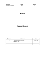
Rating plate example
The SERIAL consists of one symbol, two characters indicating the production
year and month, and six characters indicating the control number.
The last digit of the production year is indicated as the Year, and the Month is
indicated by 1 to 9, X (October), Y (November), or Z (December).
Symbol Year Month Control number
SERIAL
Rating plate
Input rating
Output rating
SERIAL
Inverter model
Country of origin
F R - A 8 4 2 -
09620
- 1 - P
400 V class
Symbol Voltage class
4
CA
Symbol Type∗1
FM
2
1
Symbol
Circuit board coating
(conforming to IEC 60721-3-3 3C2/3S2)
WithoutNone
With
With
Plated
conductor
With06
60
Without
Without
Symbol Description
400K to 500K
09620 to 12120
ND rated inverter capacity (kW)
nverter rated current
(SLD rated current of the single standard FR-A802) (A)
Symbol Structure, functionality
Separated converter type
2
Parallel operation
Symbol Function
P

Inverter component names
INTRODUCTION
9
1
1.2 Inverter component names
Component names are shown below.
Refer to the FR-A800 Instruction Manual (Detailed).
The Vector control compatible options cannot be used with the slave.
Symbol Name Description
Refer to
page
(a) RS-485 terminals
Enables RS-485 communication between the master and the slave for the
parallel operation.
55
(b)
Terminating resistor selection
switch (SW1)
Select whether or not to use the terminating resistor for RS-485
communication.
55
(c) Plug-in option connector 1
Connects a plug-in option or a communication option.
Instruction
Manual of
the option
(d) Plug-in option connector 2
(e) Plug-in option connector 3
(f) Voltage/current input switch (SW2) Selects between voltage and current for the terminal 2 and 4 inputs.
(g) Control circuit terminal block Connects cables for the control circuit. 40
(h) PU connector
Connects the operation panel or the parameter unit. This connector also
enables the RS-485 communication.
57
(i) USB A connector Connects a USB memory device. 58
(j) Power lamp Stays ON while the power is supplied to the control circuit (R1/L11, S1/L21). 36
(k) Alarm lamp Turns ON when the protective function of the inverter is activated. 85
(l) Charge lamp Stays ON while the power is supplied to the main circuit. 36
(m) Operation panel (FR-DU08) Operates and monitors the inverter.
(n) Upper front cover
Remove this cover for the installation of the product, installation of a plug-in
(communication) option, RS-485 terminal wiring, switching of the voltage/
current input switch, etc.
16
(o) Lower front cover Remove this cover for wiring. 16
(p) Main circuit terminal block Connects cables for the main circuit. 35
(q) Cooling fan Cools the inverter. 98
(r)
Switches for manufacturer setting
(SW3 and SW4)
Do not change the initial setting (OFF ). If the setting is changed, a
protective function (E.SAF) may be activated.
─
(h)
(g)
(f)
(p)
(j)
(l)
(a)
(e)
(c)
(d)
(m)
(k)
(n)
(o)
(i)
(q)
(r)
(b)
OFF
ON

About the related manuals
10
INTRODUCTION
1.3 About the related manuals
Manuals related to this product are shown in the following table.
Manual name Manual number
Parallel Operation Function Manual IB-0600654ENG
FR-A800 Instruction Manual (Detailed) IB-0600503ENG
FR-CC2-P Instruction Manual IB-0600657ENG
FR-A802-P Safety Stop Function Instruction Manual BCN-A23228-019

2
INSTALLATION AND WIRING
11
2 INSTALLATION AND
WIRING
This chapter explains the "installation" and the "wiring" of this
product.
Always read the instructions before using the equipment.
2.1 Peripheral devices ....................................................................12
2.2 Removal and reinstallation of the operation panel or the
front covers ...............................................................................16
2.3 Installation of the inverter and enclosure design ..................18
2.4 Terminal connection diagrams ................................................25
2.5 Main circuit terminals ...............................................................35
2.6 Control circuit ...........................................................................40
2.7 Communication connectors and terminals............................55
2.8 Connection of motor with encoder (Vector control)..............59
2.9 Parameter settings for a motor with encoder ........................65

Peripheral devices
12
INSTALLATION AND WIRING
2.1 Peripheral devices
2.1.1 Inverter and peripheral devices
• For operating two inverters in parallel (for driving a single wound motor)
(c) Three-phase AC
power supply
One circuit breaker and one magnetic contactor per converter unit
One circuit breaker and one magnetic contactor in total in a system
To the master converter unit
To the slave converter unit
(d) Molded case circuit
breaker (MCCB) or fuse
(e) Magnetic
contactor
(MC)
(f) Noise filter
(g) Noise filter
R/L1
S/L2
T/L3
N/-
P/+
N/-
P/+
U
V
W
(b) Converter unit
(FR-CC2-P)
(b) Converter unit
(FR-CC2-P)
R/L1
S/L2
T/L3
N/-
P/+
N/-
P/+
U
V
W
(a) Inverter
(FR-A802-P)
Earth (Ground)
(h) Induction
motor
Earth (Ground)
Earth (Ground)
Earth (Ground)
(a) Inverter
(FR-A802-P)
(c) Three-phase AC
power supply
(d) Molded case circuit
breaker (MCCB) or fuse
(e)
Magnetic
contactor
(MC)
(f) Noise filter
: Install these options as required.
Earth (Ground)

Peripheral devices
INSTALLATION AND WIRING
13
2
Do not use an earth leakage circuit breaker as a circuit breaker which is intended to be installed per converter unit. Doing so may cause
unintended operation of the inverter.
For every magnetic contactor installed for a converter unit in parallel connection, the ON/OFF timing of the magnetic contactors is critical to
supplying power to the converters simultaneously.
NOTE
• To prevent an electric shock, always earth (ground) the motor, the inverter, and the converter unit.
• Do not install a power factor correction capacitor or surge suppressor or capacitor type filter on the inverter's output side. Doing
so will cause the inverter output shutoff or the capacitor and surge suppressor to be damaged. If any of the above devices is
connected, immediately remove it. When installing a molded case circuit breaker on the output side of the inverter, contact the
manufacturer of the molded case circuit breaker.
• Electromagnetic wave interference
The input/output (main circuit) of the inverter or the converter unit includes high frequency components, which may interfere
with the communication devices (such as AM radios) used near the inverter or the converter unit. In this case, activating the
EMC filter of the converter unit may minimize interference. (Refer to page 74.)
• For details of options and peripheral devices, refer to the respective Instruction Manual.
2.1.2 Peripheral devices
Selecting the converter unit
According to the connected motor capacity, configure the converter units and the inverters as follows.
The capacity of all converter units must be the same in a system, and that of all inverters also must be the same.
(When a single wound motor is connected)
The motor capacity indicates the maximum capacity of a 4-pole motor driven by all of the inverters in parallel connection.
Symbol Name Overview
Refer
to
page
(a) Inverter (FR-A802-P)
The life of the inverter and the converter unit is influenced by the
surrounding air temperature.
The surrounding air temperature should be as low as possible within the
permissible range. This must be noted especially when the inverter is
installed in an enclosure.
Incorrect wiring may lead to damage of the inverter and the converter unit.
The control signal lines must be kept fully away from the main circuit lines to
protect them from noise.
The converter unit built-in EMC filter can reduce the noise.
18
25
74
(b) Converter unit (FR-CC2-P)
(c) Three-phase AC power supply
Must be within the permissible power supply specifications of the converter
unit.
106
(d)
Molded case circuit breaker (MCCB),
earth leakage circuit breaker (ELB), or
fuse
Must be selected carefully since an inrush current flows in the converter unit
at power ON.
13
(e)
Magnetic contactor (MC)
Install this to ensure safety.
Do not use this to start and stop the inverter. Doing so will shorten the life of
the inverter and the converter unit.
78
(f) Noise filter
Suppresses the noise radiated from the power supply side of the converter
unit.
71
(g) Noise filter
Install this to reduce the electromagnetic noise generated from the inverter
and the converter unit. The noise filter is effective in the range from about
0.5 MHz to 5 MHz.
71
(h) Induction motor Connect a squirrel-cage induction motor. —
Motor
capacity
(kW)
Number of
units
Converter unit
FR-CC2-[ ]-P
Inverter
LD (light duty) ND (normal duty, initial value)
Model
FR-A842-[ ]-P
Rated
current
(A)
Model
FR-A842-[ ]-P
Rated
current
(A)
630 2 H400K - - - 400K 09620 1232
710 2 H450K 400K 09620 1386 450K 10940 1386
800 2 H500K 450K 10940 1539 500K 12120 1539
900 2 H560K 500K 12120 1750 - - -
945 3 H400K - - - 400K 09620 1848
1065 3 H450K 400K 09620 2078 450K 10940 2078
1200 3 H500K 450K 10940 2309 500K 12120 2309
1350 3 H560K 500K 12120 2626 - - -

Peripheral devices
14
INSTALLATION AND WIRING
(When a multi-wound motor is connected under V/F control or Advanced magnetic flux vector control)
The motor capacity indicates the maximum capacity of a 4-pole motor driven by all of the inverters in parallel connection.
(When a multi-wound motor is connected under Real sensorless vector control or Vector control)
The motor capacity indicates the maximum capacity of a 4-pole motor driven by all of the inverters in parallel connection.
Selecting the breaker/magnetic contactor
Check the model of the inverter and the converter unit you purchased. Appropriate peripheral devices must be selected
according to the capacity.
Refer to the table below to prepare appropriate peripheral devices.
• One circuit breaker and one magnetic contactor in total in a system
(When a single wound motor or a multi-wound motor is connected under V/F control or Advanced magnetic flux vector control )
(When a multi-wound motor is connected under Real sensorless vector control or Vector control)
Motor
capacity
(kW)
Number of
units
Converter unit
FR-CC2-[ ]-P
Inverter
LD (light duty) ND (normal duty, initial value)
Model
FR-A842-[ ]-P
Rated
current
(A)
Model
FR-A842-[ ]-P
Rated
current
(A)
630 2 H400K - - - 400K 09620 1232
710 2 H450K 400K 09620 1386 450K 10940 1386
800 2 H500K 450K 10940 1539 500K 12120 1539
900 2 H560K 500K 12120 1750 - - -
Motor
capacity
(kW)
Number of
units
Converter unit
FR-CC2-[ ]-P
Inverter
LD (light duty) ND (normal duty, initial value)
Model
FR-A842-[ ]-P
Rated
current
(A)
Model
FR-A842-[ ]-P
Rated
current
(A)
800 2 H400K - - - 400K 09620 1540
900 2 H450K 400K 09620 1732 450K 10940 1732
945 2 H500K 450K 10940 1924 500K 12120 1924
1065 2 H560K 500K 12120 2188 - - -
Motor
capacity
(kW)
Number of
units
Converter unit
FR-CC2-[ ]-P
Molded case circuit breaker (MCCB)
or earth leakage circuit breaker (ELB)
(type NF or NV)
Input-side magnetic
contactor
630 2 H400K 1500 A 1300 A rated product
710 2 H450K 1600 A 1400 A rated product
800 2 H500K 1800 A 1600 A rated product
900 2 H560K 2100 A
1800 A rated product
945 3 H400K 2200 A
1900 A rated product
1065 3 H450K 2400 A
2100 A rated product
1200 3 H500K 2700 A
2400 A rated product
1350 3 H560K 3100 A
2700 A rated product
Motor
capacity
(kW)
Number of
units
Converter unit
FR-CC2-[ ]-P
Molded case circuit breaker (MCCB)
or earth leakage circuit breaker (ELB)
(type NF or NV)
Input-side magnetic
contactor
800
2
H400K 1800 A 1600A rated product
900 H450K 2100 A 1800A rated product
945 H500K 2200 A 1900A rated product
1065 H560K 2400 A 2100A rated product
The motor output indicates the output power of a 4-pole motor at 400 VAC 50 Hz driven by all of the inverters in parallel connection.
Select an MCCB according to the power supply capacity.
(For the use in the United States or Canada, refer to page 115 to select an appropriate fuse or molded case circuit breaker (MCCB).)
The magnetic contactor is selected based on the AC-1 class. The electrical durability of magnetic contactor is 500,000 times. When the
magnetic contactor is used for emergency stops during motor driving, the electrical durability is 25 times.
If using an MC for emergency stop during driving the motor, select an MC regarding the converter unit input side current as JEM 1038-AC-3
class rated current. When using an MC on the inverter output side for commercial-power supply operation switching using a general-purpose
motor, select an MC regarding the rated motor current as JEM 1038-AC-3 class rated current.
An air circuit breaker is also applicable in a system in which a 2000 A breaker or higher is applicable.

Peripheral devices
INSTALLATION AND WIRING
15
2
• One circuit breaker and one magnetic contactor per converter unit
(When a single wound motor or a multi-wound motor is connected under V/F control or Advanced magnetic flux vector control )
(When a multi-wound motor is connected under Real sensorless vector control or Vector control)
NOTE
• When the breaker on the converter unit's input side trips, check for the wiring fault (short circuit), damage to internal parts of
the inverter and the converter unit, etc. The cause of the trip must be identified and removed before turning ON the power of
the breaker.
Motor
output
(kW)
Number of
units
Applicable
converter unit
FR-CC2-[ ]-P
Molded case circuit breaker (MCCB)
(NF type)
Input-side magnetic
contactor
630 2 H400K 900 A S-N800
710 2 H450K 1000 A 1000 A rated product
800 2 H500K 1200 A 1000 A rated product
900 2 H560K 1500 A 1200 A rated product
945 3 H400K 900 A S-N800
1065 3 H450K 1000 A 1000 A rated product
1200 3 H500K 1200 A 1000 A rated product
1350 3 H560K 1500 A 1200 A rated product
Motor
output
(kW)
Number of
units
Applicable
converter unit
FR-CC2-[ ]-P
Molded case circuit breaker (MCCB)
(NF type)
Input-side magnetic
contactor
800
2
H400K 900A S-N800
900 H450K 1000A 1000 A rated product
1000 H500K 1200A 1000 A rated product
1120 H560K 1500A 1200 A rated product
The motor output indicates the output power of a 4-pole motor at 400 VAC 50 Hz driven by all of the inverters in parallel connection.
Select an MCCB according to the power supply capacity.
(For the use in the United States or Canada, refer to page 115 to select an appropriate fuse or molded case circuit breaker (MCCB).)
The magnetic contactor is selected based on the AC-1 class. The electrical durability of magnetic contactor is 500,000 times. When the
magnetic contactor is used for emergency stops during motor driving, the electrical durability is 25 times.
If using an MC for emergency stop during driving the motor, select an MC regarding the converter unit input side current as JEM 1038-AC-3
class rated current. When using an MC on the inverter output side for commercial-power supply operation switching using a general-purpose
motor, select an MC regarding the rated motor current as JEM 1038-AC-3 class rated current.

Removal and reinstallation of the operation panel or the front covers
16
INSTALLATION AND WIRING
2.2 Removal and reinstallation of the operation
panel or the front covers
Removal and reinstallation of the operation panel
Removal of the lower front cover
(a) Remove the mounting screws to remove the lower front cover. (The number of the mounting screws differs by the capacity.)
(b) With the lower front cover removed, the main circuit terminals can be wired.
• Loosen the two screws on the operation panel.
(These screws cannot be removed.)
• Press the upper edge of the operation panel while pulling
out the operation panel.
To reinstall the operation panel, align its connector on the back with the PU connector of the inverter, and insert the operation
panel. After confirming that the operation panel is fit securely, tighten the screws. (Tightening torque: 0.40 to 0.45 N·m)
(a) (b)

Removal and reinstallation of the operation panel or the front covers
INSTALLATION AND WIRING
17
2
Removal of the upper front cover
(a) With the lower front cover removed, loosen the mounting screws on the upper front cover. These screws cannot be removed.
(b) While holding the areas around the installation hooks on the sides of the upper front cover, pull out the upper front cover using its
upper side as a support.
(c) With the upper front cover removed, wiring of the control circuit and the RS-485 terminals, and installation of the plug-in option
can be performed.
Reinstallation of the front covers
(a) Clip on the upper front cover as illustrated.
Check that it is properly secured.
(b) Tighten the screws on the lower part of the upper front cover.
(c) Attach the lower front cover using the screws. The number of screws differs depending on the capacity of the inverter.
NOTE
• When installing the upper front cover fit the connector of the operation panel securely along the guides of the PU connector.
• Fully make sure that the front covers are installed securely. Always tighten the mounting screws of the front covers.
(a) (b)
(c)
Loosen
Loosen
Loosen
(b) (c)
(a)
TightenTightenTighten
TightenTightenTighten

Installation of the inverter and enclosure design
18
INSTALLATION AND WIRING
2.3 Installation of the inverter and enclosure design
When designing or manufacturing an inverter enclosure, determine the structure, size, and device layout of the enclosure by
fully considering the conditions such as heat generation of the contained devices and the operating environment. An inverter
uses many semiconductor devices. To ensure higher reliability and long period of operation, operate the inverter in the
ambient environment that completely satisfies the equipment specifications.
2.3.1 Inverter installation environment
The following table lists the standard specifications of the inverter installation environment. Using the inverter in an
environment that does not satisfy the conditions deteriorates the performance, shortens the life, and causes a failure. Refer to
the following points, and take adequate measures.
Standard environmental specifications of the inverter
Temperature applicable for a short time, e.g. in transit.
For the installation at an altitude above 1000 m, consider a 3% reduction in the rated current per 500 m increase in altitude.
Temperature
The permissible surrounding air temperature of the inverter is between -10°C and +50°C. Always operate the inverter within
this temperature range. Operation outside this range will considerably shorten the service lives of the semiconductors, parts,
capacitors and others. Take the following measures to keep the surrounding air temperature of the inverter within the specified
range.
(a) Measures against high temperature
• Use a forced ventilation system or similar cooling system. (Refer to page 21.)
• Install the enclosure in an air-conditioned electric chamber.
• Block direct sunlight.
• Provide a shield or similar plate to avoid direct exposure to the radiated heat and wind of a heat source.
• Ventilate the area around the enclosure well.
(b) Measures against low temperature
• Provide a space heater in the enclosure.
• Do not power OFF the inverter. (Keep the start signal of the inverter OFF.)
(c) Sudden temperature changes
• Select an installation place where temperature does not change suddenly.
• Avoid installing the inverter near the air outlet of an air conditioner.
• If temperature changes are caused by opening/closing of a door, install the inverter away from the door.
NOTE
• For the amount of heat generated by the inverter unit, refer to page 20.
Item Description
Surrounding air temperature -10 to +50°C (non-freezing)
Surrounding air humidity
With circuit board coating (conforming to IEC 60721-3-3 3C2/3S2) 95% RH or less (non-condensing)
Without circuit board coating 90% RH or less (non-condensing)
Storage temperature -20 to + 65°C
Atmosphere Indoors (free from corrosive gas, flammable gas, oil mist, dust and dirt)
Altitude Maximum 2500 m
Vibration
2.9 m/s
2
or less at 10 to 55 Hz (directions of X, Y, Z axes)
Measurement
position
Measurement
position
Inverter
5 cm
5 cm
5 cm

Installation of the inverter and enclosure design
INSTALLATION AND WIRING
19
2
Humidity
Operate the inverter within the ambient air humidity of usually 45 to 90% (up to 95% with circuit board coating). Too high
humidity will pose problems of reduced insulation and metal corrosion. On the other hand, too low humidity may cause a
spatial electrical breakdown. The insulation distance defined in JEM 1103 "Control Equipment Insulator" is humidity of 45 to
85%.
(a) Measures against high humidity
• Make the enclosure enclosed, and provide it with a hygroscopic agent.
• Provide dry air into the enclosure from outside.
• Provide a space heater in the enclosure.
(b) Measures against low humidity
Air with proper humidity can be blown into the enclosure from outside. Also when installing or inspecting the unit, discharge
your body (static electricity) beforehand, and keep your body away from the parts and patterns.
(c) Measures against condensation
Condensation may occur if frequent operation stops change the in-enclosure temperature suddenly or if the outside air
temperature changes suddenly.
Condensation causes such faults as reduced insulation and corrosion.
• Take the measures against high humidity in (a).
• Do not power OFF the inverter. (Keep the start signal of the inverter OFF.)
Dust, dirt, oil mist
Dust and dirt will cause such faults as poor contacts, reduced insulation and cooling effect due to the moisture-absorbed
accumulated dust and dirt, and in-enclosure temperature rise due to a clogged filter. In an atmosphere where conductive
powder floats, dust and dirt will cause such faults as malfunction, deteriorated insulation and short circuit in a short time.
Since oil mist will cause similar conditions, it is necessary to take adequate measures.
Countermeasure
• Place the inverter in a totally enclosed enclosure.
Take measures if the in-enclosure temperature rises. (Refer to page 21.)
• Purge air.
Pump clean air from outside to make the in-enclosure air pressure higher than the outside air pressure.
Corrosive gas, salt damage
If the inverter is exposed to corrosive gas or to salt near a beach, the printed board patterns and parts will corrode or the
relays and switches will result in poor contact.
In such places, take the measures given above.
Explosive, flammable gases
As the inverter is non-explosion proof, it must be contained in an explosion-proof enclosure. In places where explosion may
be caused by explosive gas, dust or dirt, an enclosure cannot be used unless it structurally complies with the guidelines and
has passed the specified tests. This makes the enclosure itself expensive (including the test charges). The best way is to
avoid installation in such places and install the inverter in a non-hazardous place.
High altitude
Use the inverter at an altitude of within 2500 m. For use at an altitude above 1000 m, derate the rated current 3% per 500 m.
If it is used at a higher place, it is likely that thin air will reduce the cooling effect and low air pressure will deteriorate dielectric
strength.
/