Page is loading ...

54-0359 Rev. A
Technical Support
If you need technical assistance, please contact KVH Technical
Support:
North America, South America, Australia:
Phone: +1 401 847-3327
Email: [email protected]
Europe, Middle East, Asia:
Phone: +45 45 160 180
Email: [email protected]
1
These instructions explain how to install the TracVision R5/R4
satellite TV antenna system on an RV or motor coach. Complete
instructions on how to use the system are provided in the User’s
Guide and your selected receiver’s user manual.
Step See Page
1. Inspect Parts and Get Tools 2
2. Plan the Installation 3
3. Remove the Shipping Restraints 4
4a. Mount the Antenna (Standard) 5
4b. Mount the Antenna (Alternate) 6
5. Cut the Switchplate Mounting Hole 7
6. Wire the Antenna 8
7. Seal the Cable Access Hole 9
8. Wire the Receiver(s) 10
9. Wire the Switchplate 11
10. Mount the Switchplate 12
11a. Install Satellites (DISH 311 Receivers Only) 13
11b. Install Satellites 14
12. Find the Skew Angle (Europe Only) 16
13. Set the Skew Angle (Europe Only) 17
14. Test the System 18
15. Educate the Customer 19
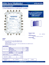
TracVision
®
R5/R4 Installation Guide
Satellite Receiver 1
TV 1
Data/Power
Vehicle
Power
11-16 VDC
Switchplate
Satellite Receiver 2
TV 2
TracVision Antenna
RF2
(Optional -
North American
Systems Only)
RF1
Baseplate
Radome

TracVision R4, R5, R4SL, R5SL, C3
1
Addendum
PLEASE READ!
Important Addendum to Your Product Manual
This addendum applies to the following TracVision antenna models:
R4, R5, R4SL, R5SL, and C3.
New Switchplate Design
The switchplate provided with
your system differs slightly from
the version shown in your manual.
Its input power connections are
simple power terminals rather than
a recessed terminal block.
To connect vehicle/vessel power to
this new switchplate, follow the
steps below.
a. Disconnect vehicle/vessel power. Test the circuit to
ensure that no power is present.
b. Crimp the supplied terminal connectors onto the
vehicle/vessel power wires (the DC power wires if
using an AC/DC power supply).
c. Carefully push the connectors onto the switchplate’s
input power terminals as shown in the illustration
below.
All other installation and operation steps remain the same as described
in the manual.
+15 VDC (Red)
Ground (Black)
Vehicle/Vessel Power
+
–
ECO #8280
Note: Strain-relieve the wires to
ensure a reliable connection.

TracVision R5SL/R4SL/R5/R4/C3
1
Addendum
PLEASE READ!
Important Addendum to Your Product Manual
This addendum applies to the following TracVision antenna models:
R4, R5, R4SL, R5SL, and C3.
Power Supply and Grounding Kit
A 15-volt, 4-amp power supply and grounding kit are now included
with your TracVision system. Be sure to install these components as
explained in this addendum.
The power supply will ensure a stable power input to the TracVision
antenna. (Low power, fluctuating power, and RF noise can affect the
antenna’s performance.) The grounding block will provide a single
ground point for the system and provide lightning protection.
Installing the Power Supply
Follow the steps below to install the supplied power supply.
a. Disconnect vehicle/vessel power. Test the circuit to
ensure that no power is present.
b. Connect the power supply’s power and ground wires
to the switchplate’s input power terminals, as shown in
the diagram on the following page.
c. Plug the power supply into vehicle/vessel AC power.
Power Supply
Grounding Block
ECO #8286

TracVision R5SL/R4SL/R5/R4/C3
2
Addendum
Installing the Grounding Block
Follow the steps below to install the grounding block.
a. Connect the grounding block in-line with the antenna’s
RF cable(s), between the antenna and the receiver(s), as
shown in the diagram below.
b. Mount the grounding block to a structure inside the
vehicle/vessel.
c. Attach the supplied ground wire to either ground
screw on the grounding block. Connect the other end of
the wire to vehicle/vessel AC ground.
All other installation steps remain the same as described in the
manual.
RF2
(Optional)
RF1
Receiver #2
(Optional)
SATELLITE IN
OUT TO TV
TV ANT/CABLE IN
AUDIO VIDEO S-VIDEO PHONE JACK
RL
SATELLITE IN
Receiver #1
SATELLITE IN
OUT TO TV
TV ANT/CABLE IN
AUDIO VIDEO S-VIDEO PHONE JACK
RL
SATELLITE IN
100-240 VAC
Vehicle/Vesse
l
AC Power
Switchplate
Antenna
Data/Power
Vehicle/Vessel
AC Ground
+
–
Grounding
Block
Ground
Wire
Power Supply
+15 VDC
(Red)
Ground
(Black)

54-0359 Rev. A
2
1. Unpack the box and ensure it contains everything
shown on the supplied Contents List. Cables for the
R5/R4 system are stored beneath the antenna unit
during shipping.
2. Carefully examine all of the supplied parts to
ensure nothing was damaged in shipment.
3. Gather all of the tools and materials listed below.
You will need these items to complete the
installation.
• Electric drill
• 3/16" (5 mm), 5/32" (4 mm), and 3/32"
(2.5 mm) drill bits
• 3/4" (19 mm) hole saw and auger bit
• 9/64" allen wrench (European systems only)
• Phillips and Flat head screwdrivers
• RG-6 or RG-11 (75 ohms) RF cable (if installing two
RF cables)
• Silicone sealant, RTV, or equivalent
• 7/16" open-end wrench
• Construction adhesive suitable for the roof
• Fasteners suitable for mounting the antenna to the
roof
• Augat IT1000 crimp/strip tool
(KVH Part # 19-0242)
• PC with the latest version of the KVH Flash
Update Wizard installed
Always lift the antenna by the
baseplate, never by the radome!
The Flash Update Wizard is
available to KVH-authorized dealers
through the KVH Partner Portal.
Inspect Parts and Get Tools
1

54-0359 Rev. A
3
Before you begin, consider the following installation guidelines:
• Minimize blockage. The antenna needs a clear view of
the sky to receive satellite TV. Using the table as a
guide, mount the antenna a suitable distance away
from obstructions on the roof, such as air
conditioners.
• Find a location on a flat part of the roof on the
centerline of the vehicle.
• The antenna must be mounted on a horizontal
surface. When placed flat on the mounting surface,
the mounting plates should be less than 7/16
" above
the mounting surface.
• When choosing a location for the switchplate, find a
dry, flat location that will be easily accessible to the
user. Take into account cable lengths between
components, as well as accessibility to the equipment
after installation.
Blocked!
Vehicle Roof
Obstruction
AA
B
Antenna
Antenna Blockage
Height of
Obstruction (A)
Minimum Distance
from Antenna (B)
8" 6"
10" 12"
12" 17"
14" 23"
16" 28"
Any gap larger than 7/16" will warp
the baseplate and seriously damage
the antenna.
Maximum Mounting Surface Slope
" Maximum Gap
7
16
Plan the Installation
2

54-0359 Rev. A
4
1. At the bottom of the antenna baseplate, cut the
two tie-wraps and pull them out of the baseplate
tie-wrap holes. You do not need to remove the
radome. The tie-wraps secure the antenna
mechanism to prevent shipping damage.
2. After removing the tie-wraps, seal the four tie-
wrap holes with the plugs provided in the
kitpack.
Exercise caution when handling the
antenna after removing the shipping
restraints. Improper handling may
damage the unit.
You do not need to remove the
radome in order to remove the
shipping restraints.
Tie-wrap Hole Locations on Baseplate (Bottom View)
Forward
Tie-wrap
Holes
Rear
Tie-wrap
Holes
Remove the Shipping Restraints
3

54-0359 Rev. A
5
You can mount the antenna with the baseplate connectors facing
the rear of the vehicle (standard orientation), or with the
baseplate connectors facing the front of the vehicle (alternate
orientation). Follow the steps below to mount the antenna in the
standard orientation. To mount the antenna in the alternate
orientation, skip to “Mount the Antenna (Alternate)” on page 6.
1. Place the antenna on the roof on the centerline of
the vehicle, ensuring the arrow on the antenna’s
front mounting plate faces the front of the vehicle.
2. Apply construction adhesive to the bottom of the
antenna’s three mounting plates, across all holes.
3. Attach the three mounting plates to the roof using
15 fasteners appropriate for the roof’s
construction.
4. Seal all fasteners with silicone sealant or
equivalent.
Vehicle
Centerline
Front of
Vehicle
Mounting Plate
(1 of 3)
Baseplate
Connectors
Top View
Side View
Baseplate
Connectors
Front of
Vehicle
Vehicle
Centerline
Forward Mounting
Plate Arrow
Standard Antenna Orientation
Due to the variation in RV roof
construction, consult with the RV
manufacturer to determine the safest
fastening method.
Mount the Antenna (Standard)
4a

54-0359 Rev. A
6
If you wish to mount the antenna with the baseplate connectors
facing the front of the vehicle (alternate orientation), you will
need to remove the radome, drill drain holes in the antenna
baseplate, then seal the existing factory-drilled drain holes.
Follow the steps below to mount the antenna in the alternate
orientation.
1. Remove the eight screws and washers securing
the radome to the baseplate. Carefully lift the
radome up until clear of the antenna assembly
and set aside.
2. Drill out three 3/16"
(5 mm) drain holes in the
rear-facing side of the baseplate. Then plug the
four existing factory-drilled drain holes with
silicone sealant.
3. Reinstall the radome, then place the antenna on
the roof on the centerline of the vehicle, ensuring
the baseplate connectors face the front of the
vehicle.
4. Follow Steps 2, 3, and 4 of “Mount the Antenna
(Standard)” on page 5 to complete the antenna
mounting procedure.
(Alternate Orientation Only)
You MUST drill out the drain holes
as indicated to ensure that any
moisture that enters the baseplate is
able to drain. Ensure that the
factory-drilled holes are completely
sealed.
Front of
Vehicle
Drain Hole Angles
(relative to baseplate)
Seal Factory-drilled
Drain Holes
Drain Hole
(Angle relative to front)
Drain Hole
(Angle relative to front)
Drain Hole
Vehicle
Centerline
Drill Out Alternate
Drain Holes
Front of
Vehicle
Baseplate
Connectors
Vehicle
Centerline
Alternate Antenna Orientation/Drain Hole Locations
Mount the Antenna (Alternate)
4b

54-0359 Rev. A
7
1. Find a dry, flat location inside the vehicle within
27 feet of the antenna to mount the switchplate.
The switchplate must be easily accessible to the
user.
2. Using the template supplied in Appendix F on
page 33, cut out the switchplate mounting hole in
the mounting surface.
A full-scale panel cutout template
has been provided for you in
Appendix F on page 33.
3.82"
(97 mm)
.32" (8 mm)
2.36"
(60 mm)
.16" (4 mm)
3.19"
(81 mm)
2.05"
(52 mm)
Panel Cutout
3
/32" (2.5 mm) dia
Switchplate Cutout Dimensions
Be sure to consider the 28-foot
length of the data/power cable when
choosing a location for switchplate. If
y
ou require a longer cable, an
additional power supply MUST be
used. Failure to install an additional
power supply when a longer cable is
used can result in serious damage to
the antenna unit. KVH offers several
cable packages:
45' Cable with Power Supply
KVH Part # 72-0143-45
60' Cable with Power Supply
KVH Part # 72-0143-60
45' Cable without Power Supply
KVH Part # 32-0730-45
60' Cable without Power Supply
KVH Part # 32-0730-60
Power Supply
KVH Part # 19-0402
Cut the Switchplate Mounting Hole
5

54-0359 Rev. A
8
1. Drill a 3/4" hole in the roof for the cable access
hole. Smooth the edges of the hole to prevent
chafing of the cable.
2. Connect the antenna data/power cable to the
antenna’s center connector and lock in place.
3. Connect one RF cable to the antenna’s “RF1”
connector. Hand-tighten first, then tighten with a
7/16
" wrench for 1/4 turn.
4. Slide the rubber sealing boot up the RF cable until
it covers the connector. This boot will help protect
the connector from the elements.
5. (North American Systems Only) - If you plan to
connect more than one receiver, connect a second
RF cable to the “RF2” connector, then slide the
rubber sealing boot up the RF cable.
6. Route the cables down through the cable access
hole in the roof. Be sure to maintain a service loop
(approximately 8") on the roof to allow plenty of
slack.
7. Route the data/power cable to the switchplate
location inside the vehicle.
8. Route the RF1 cable to the receiver. If you
connected a second RF cable, route the RF2 cable
to the second receiver.
Antenna Baseplate Connectors
RF2
(to 2nd Receiver)
North American
Systems only
RF1
(to Receiver)
Data/Power
(to Switchplate)
Leave the protective cap installed on
the RF2 connector unless
connecting a second RF cable.
(North American Systems Only)
If you need to connect three or more
receivers, refer to Appendix B on
page 22.
Wire the Antenna
6

54-0359 Rev. A
9
1. Seal the cable access hole with a liberal amount of
silicone sealant, RTV, or equivalent to protect
against leakage.
2. Install the clamshell ventilator, supplied in the
kitpack, over the cable access hole using three of
the supplied #6 screws.
Clamshell
Ventilator
#6 Screws
Cable Access Hole
(in Roof of Vehicle)
Data/Power
& RF Cables
To TracVision
Antenna
Installing the Clamshell Ventilator
Seal the Cable Access Hole
7

54-0359 Rev. A
10
If you cut the RF cable(s), be sure to use an Augat IT1000
crimp/strip tool (KVH Part # 19-0242) to attach an F-connector.
1. Connect the RF1 cable to the receiver’s “Satellite
In” connector.
2. Connect one end of the supplied ground wire to
any suitable screw on the receiver’s rear panel
with a good contact with the receiver chassis.
Route the other end to the switchplate location.
3. If you need to connect a second receiver, connect
the RF2 cable and a second ground wire to the
second receiver. If you need to connect more than
two receivers, you will need to install an active
multiswitch; see Appendix B on page 22.
Augat IT1000 Crimp/Strip Tool and F-connector
Do not use a screw-on, push-on, or
twist-on connector. Low quality
connectors will degrade system
performance and allow water/rain to
penetrate the cable.
Receiver “Satellite In” Connector (Example)
SATELLITE IN
OUT TO TV
TV ANT/CABLE IN
(NOT SATELLITE)
RL
AUDIO VIDEO S-VIDEO
DIGITAL
AUDIO OUT
PHONE JACK
DATA PORT
SATELLITE IN
Wire the Receiver(s)
8

54-0359 Rev. A
11
The TracVision system requires an 11-16 VDC power input. A
quick-tripping circuit breaker should be installed between the
switchplate and vehicle power. Circuit overload protection
should be rated for 5 amps. If vehicle power fluctuates widely or
is noisy, a 12 VDC 5-amp AC/DC power supply should be
installed (KVH Part # 19-0402 or equivalent).
1. Disconnect vehicle power by removing the
appropriate vehicle fuse. Test the circuit to ensure
that no power is present.
2. Connect the antenna’s data/power cable to the
switchplate’s data/power connector and lock in
place.
3. Connect the receiver ground wire(s) to the
switchplate’s ground terminal, as shown above.
4. Connect the switchplate to vehicle power and
ground, as shown above.
Before wiring the switchplate, be
sure to disconnect vehicle power by
removing the appropriate vehicle
fuse. Test the circuit to ensure that
no power is present.
+12 VDC – Vehicle Power
Ground
Data/Power
Receiver Ground
Wire
Switchplate Connections
Wire the Switchplate
9

54-0359 Rev. A
12
1. Fit the switchplate flush into the switchplate
panel cutout that you made earlier.
2. Drill out four 5/32" (4 mm) holes in the screw
cavities in the switchplate.
3. Drill four 3/32" (2.5 mm) holes in the mounting
surface using the switchplate screw cavities as the
template. Then secure the switchplate assembly to
the mounting surface using four #6 self-cutting
screws.
4. Gently snap the switchplate cover onto the
switchplate.
5. Reconnect vehicle power. Be sure to replace the
vehicle fuse that you removed earlier.
Switchplate Mounting
3.82"
(97 mm)
2.36"
(60 mm)
2.05"
(52 mm)
3.19"
(81 mm)
A. Panel Cutout
B. Switchplate
C. Switchplate Cover
Screw Cavities
5
/
32
" (4 mm)
3
/
32
" (2.5 mm)
Mount the Switchplate
10

54-0359 Rev. A
13
The following instructions explain how to install satellites for
DISH Network service for use with DISH 311 receivers only.
DISH Network does not currently support the use of any other
receivers for mobile customers. This procedure does not require a
PC. To install satellites for any other receiver model, proceed to
“Install Satellites” on page 14.
1. Turn on the TV and primary receiver (the receiver
connected to RF1).
2. Set the switchplate’s POWER switch to the ON
(up) position. Wait one minute for system startup.
3. Using the receiver remote control, go to the “Point
Dish/Signal Strength” screen (press MENU,
6, 1, 1).
4. Choose “Check Switch” then press SELECT.
5. Choose “Test” then press SELECT to run the
Check Switch function. Wait 15 minutes for the
antenna to install and find both DISH satellites.
6. Choose “Test” then press SELECT to run the
Check Switch function a second time.
7. Once the second Check Switch function is
complete, ensure the TV display appears exactly
as shown below:
If the TV display does not appear exactly as shown, run the
Check Switch function again.
8. Exit the menu and allow the receiver to download
the program guide.
9. The procedure is complete! Skip to “Test the
System” on page 18.
Installed Switch: SW42
Input: 1 1 2 2
Satellite: 119 119 110 110
Polarity: Odd Even Odd Even
Status: Satellite reception verified
Ensure that the vehicle is parked in a
blockage-free area. The antenna
must have a clear view of the sky to
receive satellite TV.
ON
OFF
TracVision Switchplate
Install Satellites (DISH 311 Receivers Only)
11a

54-0359 Rev. A
14
If your TracVision system is preconfigured to track your
desired satellite pair (see sidebar at left), skip to “Test the
System” on page 18. To select a different satellite pair, you will
need to connect a PC to the antenna and start the KVH Flash
Update Wizard. This procedure requires a PC with the Flash
Update Wizard installed. The Flash Update Wizard is available
to KVH-authorized dealers through the KVH Partner Portal.
Customers who wish to change the satellites that the TracVision
system tracks can visit any KVH-authorized dealer/distributor.
The new satellites can be configured in a just a few minutes.
1. Connect one end of the supplied PC data cable to
the DB9 maintenance port connector on the
switchplate. Connect the other end to the serial
port on your PC.
2. Double-click the KVH Flash Update Wizard
shortcut on your computer’s desktop to start the
Flash Update Wizard. You do not need to flash the
antenna; you will simply enter commands in the
“TracVision Antenna Comms” window.
3. Set the switchplate’s POWER switch to the ON
(up) position, then turn on the receiver(s). Wait
one minute for system startup.
The TracVision system is
preconfigured to track one of the
following satellite pairs:
Europe:
ASTRA1 (Sat. A)
HOTBIRD (Sat. B)
N. America
DIRECTV_101 (Sat. A)
DIRECTV_119 (Sat. B)
If your computer does not have a
DB9 serial COM port, you can use
the following USB-to-RS232
adapter:
IOGear Part # GUC232A
(visit www.iogear.com)
ON
OFF
Maintenance
Port
TracVision Switchplate
Data
Display
Enter
Commands
TracVision Antenna Comms Window
Install Satellites
11b

54-0359 Rev. A
15
Follow the steps below to select which satellites to track. Enter all
commands in the “TracVision Antenna Comms” window.
4. Type
HALT then press Enter.
5. Select any two satellite names from either the
North American or European satellite library.
Also, be sure you are located within your selected
satellite’s coverage area. Visit www.kvh.com/
footprint for satellite coverage maps. If your
desired satellites are not listed, you may also add any
two satellites of your choice. To add satellites to the
library, skip to Appendix C on page 23.
6. Type the following command (see the Key below)
then press Enter.
SATINSTALL,<sat_a_name>,<sat_b_name>
NOTE: To receive DISH 500 service, install the
following two satellites: ECHO_119 & ECHO_110.
7. Type
ZAP then press Enter to restart the antenna.
Wait one minute for the antenna to initialize.
Be sure the receiver’s satellite configuration matches your
TracVision system’s settings. Your choice for Satellite A or B
must be the same satellite as Receiver Alternative 1 or 2,
respectively (or Receiver Alternative A or B, respectively), based
on your receiver, and must be assigned the Receiver DiSEqC 1 or
2 setting, respectively**. Refer to your selected receiver’s user
manual for details.
**DiSEqC settings apply only to European systems.
Key: <sat_a_name> = the name of your choice
for Satellite A
<sat_b_name> = the name of your choice
for Satellite B (type
NONE as the name
of satellite B if you wish to install only one
satellite)
Satellite Installation Names
Satellite Install Name
North American Satellites
†
DIRECTV 72.0° W
DSS_72
DIRECTV 101.0
° W
DSS_101
DIRECTV 119.0° W
DSS_119
ECHOSTAR 61.5° W
ECHO_61
ECHOSTAR 110.0
° W
ECHO_110
ECHOSTAR 119.0° W
ECHO_119
EXPRESSVU 82.0° W
EXPRESSVU
EXPRESSTV 91.0
° W
EXPRESSTV
PAS9 58°W
PAS_9
††
European Satellites
ARABSAT 26.0
° E
ARABSAT
ASTRA1 19.2° E
ASTRA1
ASTRA2N 28.2
° E
ASTRA2N
ASTRA2S 28.2° E
ASTRA2S
EUTELSAT W3A 7.0° E
EUTEL_W3A
HISPASAT 30.0
° W
HISPASAT
HOTBIRD 13.0° E
HOTBIRD
HOTBIRDWB 13.0° E
HOTBIRDWB
NILESAT 101 7.0
° W
NILESAT
SIRIUS 5.0° E
SIRIUS
THOR 0.8° W
THOR
TURKSAT1C 42.0
° E
TURKSAT1C
Other Satellite Designations
USER-DEFINED 1
USER1
†††
USER-DEFINED 2
USER2
†††
NONE NONE
†
In N. America, you can also receive an
d
decode signals from the DIRECTV 110
satellite if a KVH HDTV converter
(KVH Part # 01-0260-05) is installed.
††
Unlike other N. American satellites,
PAS9 service requires a linear
(European-style) LNB. Follow the
additional instructions for European
systems within this guide to install the
PAS9 satellite.
†††
USER1 and USER2 will only be
available if one or two user-defined
satellites have been added to the library
(see Appendix C on page 23).
To assign ASTRA2S and HOTBIRD for your satellite pair
(whereASTRA2S is designated as Satellite A and HOTBIRD is
designated as Satellite B):
Type
HALT then press Enter.
Type
SATINSTALL,ASTRAS2S,HOTBIRD then press Enter.
Type
ZAP then press Enter.
Example:
Install Satellites ctd.
11b

54-0359 Rev. A
16
To optimize channel reception, you need to set the LNB skew
angle. Refer to your satellite service provider for the proper skew
angle for your specific satellite service and geographic location.
You can also find the skew angle for satellites in the TracVision
R5/R4 satellite library by entering your latitude and longitude
into the antenna. You can use the grid below to determine your
approximate latitude/longitude.
Finding the Skew Angle for Satellites in the Satellite Library
1. Type HALT then press Enter.
2. Type
DEBUGON then press Enter.
3. Type the following command (see the Key below)
then press Enter.
GPS,XX,D,YYY,E
4. Type SKEWANGLE then press Enter. The
TracVision system will respond with the skew
angle for the currently selected satellite.
Key: XX = latitude (0-90)
D = S (South) or N (North)
YYY= longitude (0-180)
E = E (East) or W (West)
1
2
3
4
11
7
6
5
8
9
10
12
13
14
16
15
17
18
19
20
21 22 23 24
To determine your approximate latitude/longitude, match the grid # above for
y
our location with the corresponding grid # at left.
Approximate Latitude/Longitude
Grid # Latitude Longitude
167°N7°W
267°N7°E
367°N22°E
465°N44°E
563°N7°W
663°N7°E
763°N22°E
857°N7°W
957°N7°E
10 57°N 22°E
11 55°N 40°E
12 53°N 7°W
13 53°N 7°E
14 50°N 22°E
15 47°N 7°W
16 47°N 7°E
17 43°N 7°W
18 43°N 7°E
19 43°N 22°E
20 43°N 37°E
21 36°N 7°W
22 36°N 7°E
23 36°N 22°E
24 36°N 37°E
Find the Skew Angle (Europe Only)
12

54-0359 Rev. A
17
1. Turn off the antenna and remove the appropriate
vehicle fuse to disconnect power. Ensure power is
removed from both the antenna and the
receiver(s) or multiswitch connected to RF1.
2. Remove the eight screws securing the radome.
Remove the radome and set it aside in a safe
place.
3. Using a 9/64" allen wrench, loosen the two LNB
bracket screws securing the LNB in the following
way: loosen one screw one full turn, then loosen
the second screw one full turn; repeat until the
LNB can be rotated freely.
4. Rotate the LNB to align the skew arrow with the
skew angle that you determined earlier, then
tighten the screws (in the same manner that you
loosened them) until the LNB no longer rotates.
Then turn each of the two screws an additional
1/4 turn.
5. Reinstall the radome and restore vehicle power.
Be sure to replace the vehicle fuse that you
removed earlier.
Before servicing the antenna unit,
turn off the antenna and disconnect
vessel power. Ensure power is
removed from both the antenna and
the receiver(s) or multiswitch
connected to RF1.
LNB
Rotating
Plate
Radome
Screws
Radome Screws
IMPORTANT
Be sure to alternate the loosening or
tightening of the LNB bracket
screws. Turn one screw one full turn,
then turn the second screw one full
turn, until the operation is complete.
Failure to do so might cause unequal
pressure on the LNB and impair
signal reception.
LNB
LNB Bracket
Screws
LNB/LNB Bracket Assembly
SKEW
-20˚ Skew
Negative
Skews
Positive
Skews
A
lign the Skew Arrow with the Skew
A
ngle that You Determined Earlier
Set the Skew Angle (Europe Only)
13
/