U-Line U-3036RRGLINT-00B User guide

Category
Drink coolers
Type
User guide

U-Line U-3036RRGLINT-00B is a 36-inch Glass Door Refrigerator designed for seamless integration into your kitchen. It features adjustable shelves, allowing you to customize the storage space to fit your needs. The glass door provides a clear view of the contents, making it easy to find what you're looking for. With its sleek design and user-friendly features, this refrigerator is the perfect addition to any modern kitchen.

U-Line U-3036RRGLINT-00B is a 36-inch Glass Door Refrigerator designed for seamless integration into your kitchen. It features adjustable shelves, allowing you to customize the storage space to fit your needs. The glass door provides a clear view of the contents, making it easy to find what you're looking for. With its sleek design and user-friendly features, this refrigerator is the perfect addition to any modern kitchen.

USER GUIDE
SAFETY INSTALLATION & INTEGRATION OPERATING INSTRUCTIONS MAINTENANCE SERVICE
Modular 3000 Series
3036RRGL
36" Glass Door Refrigerator
RIGHT PRODUCT. RIGHT PLACE. RIGHT TEMPERATURE. SINCE 1962.
USER GUIDE
u-line.com
Contents
SAFETY • INSTALLATION & INTEGRATION • OPERATING INSTRUCTIONS • MAINTENANCE • SERVICE
Intro
Safety
Safety and Warning
Disposal and Recycling
Installation
Environmental Requirements
Electrical
Cutout Dimensions
Product Dimensions
Side by Side Installation
Anti-Tip Bracket
General Installation
Integrated Grille / Plinth Dimensions
Grille / Plinth Installation
Door Stop
Door Adjust
Operating Instructions
First Use
Sabbath Mode
Airflow and Product Loading
Interior Shelves
Refrigerator Bins / Crisper
Maintenance
Cleaning
Cleaning Condenser
Extended Non-Use
Service
Troubleshooting
Warranty
USER GUIDE
Introduction 1
u-line.com
WELCOME TO U-LINE
Congratulations on your U-Line purchase. Your product comes from a company with over five decades and three generations
of premium modular ice making, refrigeration, and wine preservation experience. U-Line continues to be the American
leader, delivering versatility and flexibility for multiple applications including residential, light commercial, outdoor and marine
use. U-Line’s complete product collection includes modular Wine Captain
®
Models, Beverage Centers, Clear Ice Machines,
Crescent Ice Makers, Glass & Solid Door Refrigerators, Drawer Models, Freezers, and Combo
®
Models.
U-Line has captivated those with an appreciation for the finer things with exceptional functionality, style, inspired innovations
and attention to even the smallest details. We are known and respected for our unwavering dedication to product design,
quality and selection. U-Line is headquartered in Milwaukee, Wisconsin and has shipped product to five continents for over
two decades and is proud to have the opportunity to ship to you.
PRODUCT INFORMATION
Looking for additional information on your product? User Guides, Quick Reference Guides, CAD Drawings, Compliance
Documentation, and Product Warranty information are all available for reference and download at u-line.com.
PROPERTY DAMAGE / INJURY CONCERNS
In the unlikely event property damage or personal injury is suspected related to a U-Line product, please take the following
steps:
1. U-Line Customer Care must be contacted immediately at +1.800.779.2547.
2. Service or repairs performed on the unit without prior written approval from U-Line is not permitted. If the unit has been
altered or repaired in the field without prior written approval from U-Line, claims will not be eligible.
SERVICE INFORMATION
Answers to Customer Frequently Asked Questions are available at u-line.com under Customer Care or you may contact our
Customer Care group directly, contact information below.
GENERAL INQUIRIES
U-Line Corporation
8900 N. 55th Street
Milwaukee, Wisconsin 53223 USA
Monday - Friday 8:00 am to 4:30 pm CST
T: +1.414.354.0300
F: +1.414.354.7905
Email: sales@u-line.com
u-line.com
SERVICE & PARTS ASSISTANCE
Monday - Friday 8:00 am to 5:30 pm CST
T: +1.800.779.2547
F: +1.414.354.5696
Service Email: onlineservice@u-line.com
Parts Email: onlineparts@u-line.com
CONNECT WITH US
Designed, engineered and assembled in WI, USA
USER GUIDE
Safety and Warning 1
u-line.com
SAFETY • INSTALLATION & INTEGRATION • OPERATING INSTRUCTIONS • MAINTENANCE • SERVICE
Safety and Warning
NOTICE
Please read all instructions before installing,
operating, or servicing the appliance.
Use this appliance for its intended purpose only and follow
these general precautions with those listed throughout this
guide:
SAFETY ALERT DEFINITIONS
Throughout this guide are safety items labeled with a
Danger, Warning or Caution based on the risk type:
DANGER
!
Danger means that failure to follow this safety
statement will result in severe personal injury or
death.
WARNING
!
Warning means that failure to follow this safety
statement could result in serious personal injury
or death.
CAUTION
!
Caution means that failure to follow this safety
statement may result in minor or moderate
personal injury, property or equipment damage.
DANGER
!
This unit contains R600a (Isobutane) which is a
flammable hydrocarbon. It is safe for regular
use. Do not use sharp objects to expedite
defrosting. Do not service without consulting the
“R600a specifications” section included in the
User Guide. Do not damage the refrigerant
circuit.
WARNING
!
Service must be done by factory authorized
service personnel. Any parts shall be replaced
with like components. Failure to comply could
increase the risk of possible ignition due to
incorrect parts or improper service.
USER GUIDE
Disposal and Recycling 1
u-line.com
SAFETY • INSTALLATION & INTEGRATION • OPERATING INSTRUCTIONS • MAINTENANCE • SERVICE
Disposal and Recycling
DANGER
!
RISK OF CHILD ENTRAPMENT. Before you throw
away your old refrigerator or freezer, take off
the doors and leave shelves in place so children
may not easily climb inside.
If the unit is being removed from service for disposal,
check and obey all federal, state and local regulations
regarding the disposal and recycling of refrigeration
appliances, and follow these steps completely:
1. Remove all consumable contents from the unit.
2. Unplug the electrical cord from its socket.
3. Remove the door(s)/drawer(s).
USER GUIDE
Environmental Requirements 1
u-line.com
SAFETY • INSTALLATION & INTEGRATION • OPERATING INSTRUCTIONS • MAINTENANCE • SERVICE
Environmental Requirements
This model is intended for indoor/interior applications only
and is not to be used in installations that are open/
exposed to natural elements.
This unit is designed to operate between 50°F (10°C) and
100°F (38°C). Higher ambient temperatures may reduce
the unit’s ability to reach low temperatures and/or reduce
ice production on applicable models.
For best performance, keep the unit out of direct sunlight
and away from heat generating equipment.
In climates where high humidity and dew points are
present, condensation may appear on outside surfaces.
This is considered normal. The condensation will
evaporate when the humidity drops.
CAUTION
!
Damages caused by ambient temperatures of
40°F (4°C) or below are not covered by the
warranty.
USER GUIDE
Electrical 1
u-line.com
SAFETY • INSTALLATION & INTEGRATION • OPERATING INSTRUCTIONS • MAINTENANCE • SERVICE
Electrical
WARNING
!
SHOCK HAZARD — Electrical Grounding
Required. Never attempt to repair or perform
maintenance on the unit until the electricity has
been disconnected.
Never remove the round grounding prong from
the plug and never use a two-prong grounding
adapter.
Altering, cutting or removing power cord,
removing power plug, or direct wiring can cause
serious injury, fire, loss of property and/or life,
and will void the warranty.
Never use an extension cord to connect power to
the unit.
Always keep your working area dry.
NOTICE
Electrical installation must observe all state and
local codes. This unit requires connection to a
grounded (three-prong), polarized receptacle
that has been placed by a qualified electrician.
The unit requires a grounded and polarized 115 VAC,
60 Hz, 15A power supply (normal household current). An
individual, properly grounded branch circuit or circuit
breaker is recommended. A GFCI (ground fault circuit
interrupter) is usually not required for fixed location
appliances and is not recommended for your unit because
it could be prone to nuisance tripping. However, be sure
to consult your local codes.
See CUTOUT DIMENSIONS for recommended receptacle
location.
USER GUIDE
Cutout Dimensions 1
u-line.com
SAFETY • INSTALLATION & INTEGRATION • OPERATING INSTRUCTIONS • MAINTENANCE • SERVICE
Cutout Dimensions
PREPARE SITE
Your U-Line product has been designed exclusively for a
built-in installation. When built-in, your unit does not
require additional air space for top, sides, or rear.
However, the front grille must NOT be obstructed.
The product is designed and manufactured for seamless
integration in the specified cutout opening shown, which
requires precise measurements. The opening must be
square and plumb front to back. Although not required,
you may choose to increase the overall cutout width for
ease of installation.
The Modular 3000 Series units are engineered with a
variety of adjustment features to help ensure a seamless
installation. Adjustable doors, leveling legs and grille will
assist in fine tuning the installation.
All 3000 Series models fully integrate into overlay/face
frame, inset or European/frameless cabinet styles and
install seamlessly into standard 24" (610 mm) depth
cabinet base.
CAUTION
!
Unit can NOT be installed behind a closed cabinet
door.
CUTOUT DIMENSIONS
Metric measurements rounded and optimized.
4"
(102 mm)
7"
(178 mm)
35-5/8"
(905 mm)
33-7/8"
(860 mm)
to
34-7/8"
(886 mm)
Preferred location
for electrical outlet
is in adjacent
cabinet.
5/8"
(16 mm)
24"
(610 mm)
USER GUIDE
Product Dimensions 1
u-line.com
SAFETY • INSTALLATION & INTEGRATION • OPERATING INSTRUCTIONS • MAINTENANCE • SERVICE
Product Dimensions
35-7/16"
(900 mm)
33-11/16" to
34-11/16"
(856 mm to
881 mm)
Not Including Handle
23-7/16" (590 mm)*
3-5/8" to 4-5/8"
(92 to 118 mm)
USER GUIDE
Side-by-Side Installation 1
u-line.com
SAFETY • INSTALLATION & INTEGRATION • OPERATING INSTRUCTIONS • MAINTENANCE • SERVICE
Side-by-Side Installation
OTHER SITE REQUIREMENTS
Side-by-Side Installation
Units must operate from separate, properly grounded
electrical receptacles placed according to each unit’s
electrical specifications requirements.
Cutout width for a side-by-side installation is the total of
the widths listed under Cutout Dimensions in each unit’s
Installation Guide. Each door can be opened individually
(one at a time) without interference.
However, to ensure unobstructed door swing (opening
both doors at the same time), 1/4" (6.4 mm) of space
needs to be maintained between the units.
Hinge-by-Hinge Installation (Mullion)
When installing two units hinge-by-hinge, 13/16" (22 mm)
is required for integrated models. Additional space may be
needed for any knobs, pulls or handles installed.
Stainless steel models which include the standard stainless
handle will require 4-9/16" (116 mm) to allow both doors
to open to 90° at the same time.
1/4" (6 mm)
13/16" (22 mm)
4-9/16" (116 mm)
USER GUIDE
Anti-Tip Bracket 1
u-line.com
SAFETY • INSTALLATION & INTEGRATION • OPERATING INSTRUCTIONS • MAINTENANCE • SERVICE
Anti-Tip Bracket
CAUTION
!
The anti-tip bracket must be installed to prevent
the unit from tipping when doors are fully
opened or excess weight is placed on the front of
the unit.
The anti-tip brackets have multiple mounting options.
Mounting will depend on your particular cabinet
configuration. Locate 6 #8x5/8" screws included with your
unit.
TOP MOUNT
For ease of installation the anti-tip brackets are
pre-installed in the top mount position.
1. Completely slide the unit into its position in the
opening. Be certain unit height is properly adjusted.
(See GENERAL INSTALLATION).
2. Open both doors completely. Make certain doors clear
surrounding cabinetry.
3. Using a 3/32" (2.50 mm) drill bit, drill 6 pilot holes
(3 for each bracket) 5/8" (16 mm) deep into bottom of
countertop. Use the anti-tip brackets as a template.
4. Install 6 #8x5/8" screws into the plate using a #2
Phillips head screwdriver.
SIDE MOUNT
Side mount position is used when you are unable to mount
the brackets to the underside of your countertop.
1. Remove the pre-installed anti-tip brackets from the top
mount position and align to the side mounting holes on
the hinge side of your model as shown.
2. Reinstall 2 screws into each anti-tip bracket, mounting
the bracket to your unit.
3. Completely slide the unit into its position in the
opening. Be certain unit height is properly adjusted.
(See GENERAL INSTALLATION).
4. Open both doors completely to gain access to the anti-
tip brackets. Make certain doors clear surrounding
cabinetry.
5. Using a 3/32" (2.50 mm) drill bit, drill 6 pilot holes (3
for each bracket) 5/8" (16 mm) deep into cabinetry
frame using the anti-tip brackets as a template.
6. Install 6 #8x5/8" screws into the plate using a #2
Phillips head screwdriver.
Left Hinged Cabinet
Right Hinged Cabinet
USER GUIDE
General Installation 1
u-line.com
SAFETY • INSTALLATION & INTEGRATION • OPERATING INSTRUCTIONS • MAINTENANCE • SERVICE
General Installation
1. Use a level to confirm
the unit is level. Level
should be placed along
top edge and side
edge as shown.
2. If the unit is not level,
remove grille and
adjust legs as
necessary. Use
included tool to adjust the height of the rear legs.
3. Confirm the unit is level after each adjustment and
repeat the previous steps until the unit is level.
INSTALLATION TIP
If the room floor is higher than the floor in the cutout
opening, adjust the rear legs to achieve a total unit rear
height of 1/8" (3 mm) less than the opening’s rear height.
Shorten the unit height in the front by adjusting the front
legs. This allows the unit to be gently tipped into the
opening. Adjust the front legs to level the unit after it is
correctly positioned in the opening.
INSTALLATION
1. Plug in the power/electrical cord.
2. Gently push the unit into position. Be careful not to
entangle the cord.
3. Re-check the leveling, from front to back and side to
side. Make any necessary adjustments. The unit’s top
surface should be approximately 1/8" (3 mm) below
the countertop.
4. Install the anti-tip bracket.
5. Remove the interior packing material and wipe out the
inside of the unit with a clean, water-dampened cloth.
Rotate Clockwise to raise rear leg.
Rotate Counter-Clockwise to lower leg.
Rotate Front Legs to Adjust
USER GUIDE
Integrated Grille - Plinth Dimensions 1
u-line.com
SAFETY • INSTALLATION & INTEGRATION • OPERATING INSTRUCTIONS • MAINTENANCE • SERVICE
Integrated Grille - Plinth
Dimensions
The 3000 series grille (plinth strip/base fascia) is fully
adjustable and can be set to match your surrounding
furniture dimensions. In addition to it’s adjustability, an
integrated grille may also be installed to truly provide a
seamless appearance.
PREPARE AND INSTALL INTEGRATED GRILLE
(PLINTH STRIP/BASE FASCIA)
1. Use the dimensions provided in the diagram to cut and
shape your integrated grille (plinth strip/base fascia)
panel. Recommended panel thickness is between 1/4"
(6 mm) and 3/8" (9 mm). Height will vary from 3-5/16"
(84 mm) to 4-5/16" (110 mm) based on your grille
(plinth strip/base fascia) height.
2. Finish or stain your grille (plinth strip/base fascia)
panel to match your surrounding furniture. Finish
front, back and edges to prevent warping. Carefully
follow the manufacturer’s recommendations for finish
application and cure times.
3. Apply double sided tape to the backside of the
integrated grill (plinth strip/base fascia). Use the
diagram below for reference. U-Line recommends
3M
VHB tape, a high strength bonding tape.
4. Remove backing paper from double sided tape.
5. Carefully align grille (plinth strip/base fascia) over
integrated panel and press into position.
INTEGRATED GRILLE (PLINTH STRIP/BASE
FASCIA) DIMENSIONS
Apply Tape To Shaded Area
32-7/16"
(825 mm)
35-5/8"
(905 mm)
1-9/16
"
(40 mm)
1-9/16"
(40 mm)
1" (25 mm)
3-5/16" to 4-5/16"
(84 mm to 110 mm)
USER GUIDE
Grille - Plinth Installation 1
u-line.com
SAFETY • INSTALLATION & INTEGRATION • OPERATING INSTRUCTIONS • MAINTENANCE • SERVICE
Grille - Plinth Installation
REMOVING AND INSTALLING GRILLE
(PLINTH STRIP/BASE FASCIA)
WARNING
!
Disconnect electrical current to the unit before
removing the grille (plinth strip/base fascia).
When using the unit, the grille (plinth strip/base
fascia) must be installed.
Edges of sheet metal may be sharp.
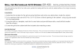
Removing the grille
(plinth strip/base fascia)
1. Disconnect electrical current to unit.
2. Using the included 7/64" Allen wrench, loosen (but do
not remove) both grille (plinth strip/base fascia) lock
screws. See below.
3. Gently pull grille (plinth strip/base fascia) away from
unit until it stops.
4. Push grille (plinth strip/base fascia) rails towards the
center of the unit to lift rails off lock screws.
5. Pull grille (plinth strip/base fascia) free from unit.
Installing the grille
(plinth strip/base fascia)
1. Align slots in
grille (plinth strip/base fascia)
rail with
screw heads in base of unit
2. Push grille (plinth strip/base fascia) rails towards the
center of the unit and set rails over screw head.
3. Slide grille (plinth strip/base fascia) into position. Using
included 7/64" Allen wrench tighten grille (plinth strip/
base fascia) lock screws.
ADJUSTING GRILLE
(PLINTH STRIP/BASE FASCIA)
The
grille (plinth strip/base fascia
) has an automatic
vertical plane adjustment and can also be adjusted on its
horizontal plane as well. To adjust your
grille (plinth strip/
base fascia
) to match your surrounding furniture, follow
the instructions below.
1. Loosen, but do not remove, the lock screws on the
inside of the
grille (plinth strip/base fascia)
rails. Lock
screws are located on the inside of each
grille (plinth
strip/base fascia)
rail.
2. The grille (plinth strip/base fascia) can be extended
horizontally by pulling out a maximum of 1-1/2"
(38 mm). Do not exceed 1-1/2" (38 mm). Secure the
lock screws after adjusting.
3. The grille (plinth strip/base fascia) skirt may be
manually adjusted to the height of your floor. Simply
raise or lower the skirt as needed.
Grille Mounting
Screws
Grille Rail
Grille
Skirt
USER GUIDE
Door Stop 1
u-line.com
SAFETY • INSTALLATION & INTEGRATION • OPERATING INSTRUCTIONS • MAINTENANCE • SERVICE
Door Stop
Your U-Line unit was shipped to you with the optional 90°
pin.
Your unit’s door(s) will open 115° straight from the
factory. If you would like the door stop at 90° follow these
instructions.
NOTICE
If your unit is already undercounter, it will need
to be moved out to access the hinge. With the
90° stop pin in place, you will not be able to
replace the hinge cover.
1. Open door approximately 90°.
2. Remove hinge cover by lifting top and bottom of hinge
cover and sliding the cover inwards to remove from
hinge.
3. Once cover is removed, slide hinge pin into hole as
shown. Pin should slide into place, stopping the door at
90°; if the pin does not go into the hole shown, hold
the door less than 90° open and try again.
4. To fully seat the pin, tap it lightly with a hammer.
5. Carefully slide your unit back in place.
NOTICE
The pin can be removed to return the door swing
back to its original 115° swing by tapping the pin
out from the bottom of the hinge.
CLOSER
The door hinge has a self-closing feature that engages
when the door is open approximately 6" (150 mm) (about
25°).
1
3
2
USER GUIDE
Door Adjustments 1
u-line.com
SAFETY • INSTALLATION & INTEGRATION • OPERATING INSTRUCTIONS • MAINTENANCE • SERVICE
Door Adjustments
DOOR ALIGNMENT AND ADJUSTMENT
Align and adjust the door if it is not level or is not sealing
properly. If the door is not sealed, the unit may not cool
properly, or excessive frost or condensation may form in
the interior.
NOTICE
Properly aligned, the door’s gasket should be
firmly in contact with the cabinet all the way
around the door (no gaps). Carefully examine
the door’s gasket to ensure that it is firmly in
contact with the cabinet. Also make sure the
door gasket is not pinched on the hinge side of
the door.
CAUTION
!
Do not attempt to use the door to raise or pivot
your unit. This would put excessive stress on the
hinge system.
Alignment and Adjustment Procedure
1. Open door and remove gasket near the hinges.
2. Using a T-25 Torx Bit, loosen each pair of Torx head
screws on both the upper and lower hinge plates.
3. Square and align door as necessary.
4. Tighten Torx head screws on hinge.
5. Reinstall gasket into the channel starting at the corner.
REVERSING THE DOOR
1. Open door.
2. Remove top hinge cover by lifting top and bottom flaps
and slide inwards. Repeat on bottom hinge.
T-25 Torx Screw
T-25 Torx Screw
Door Adjustments 2
USER GUIDE
SAFETY • INSTALLATION & INTEGRATION • OPERATING INSTRUCTIONS • MAINTENANCE • SERVICE
u-line.com
3. Using T-25 Torx bit loosen screw #1 and remove screw
#2 on top and bottom hinge. Slide and remove the
door from unit. Completely remove screw #1 on top
and bottom.
4. Remove caps from screw heads on opposite side (2 on
top and 2 on bottom). Using #2 Phillips bit remove the
4 underlying screws. Reinstall the screws and caps on
the opposite side.
5. Partially install screw #1 in the outer most holes on top
and bottom. Rotate door 180°, align hinge over screw
#1 and slide/seat into position. Reinstall screw #2 on
top and bottom. Tighten both screws and install hinge
cover.
Align and adjust the door:
Align and adjust the door (see DOOR ALIGNMENT AND
ADJUSTMENT).
2
1
USER GUIDE
First Use 1
u-line.com
SAFETY • INSTALLATION & INTEGRATION • OPERATING INSTRUCTIONS • MAINTENANCE • SERVICE
First Use
All U-Line controls are preset at the factory. Initial startup
requires no adjustments.
NOTICE
U-Line recommends allowing the unit to run
overnight before loading with product.
When plugged in, the unit will begin operating under the
factory default setting. Follow the on screen prompt for
language selection and temperature units.
To turn the unit off, press and hold for 5 seconds and
release. The display will show a countdown to switching the
unit off.
To power your unit on, simply press and the unit will
immediately switch on.
USER GUIDE
Sabbath Mode 1
u-line.com
SAFETY • INSTALLATION & INTEGRATION • OPERATING INSTRUCTIONS • MAINTENANCE • SERVICE
L
Sabbath Mode
This unit offers a Sabbath mode for users who require this
functionality during Sabbaths. Sabbath mode disables
system responses to user initiated activities and all
external functions, including lighting, display and audible
alarms. The unit will still maintain internal temperatures
and set points.
To enable Sabbath Mode:
1. Open the unit’s door to activate the display.
2. To access the Customer Menu, hold for 5 seconds.
3. Press or to scroll through available selections.
4. Select Sabbath Mode from the Customer Menu by
pressing .
5. Press to select “Off”.
6. Press . “Off” will begin to flash.
7. Press or to change “Off” to “On”.
8. Press to confirm your selection.
The Display will fade out as the unit enters Sabbath Mode.
Sabbath
Mode remains active until is quickly pressed and
released.
Up
Select
Down
RETURN TO MENU
SABBATH MODE
OFF?
USER GUIDE
Airflow and Product Loading 1
u-line.com
SAFETY • INSTALLATION & INTEGRATION • OPERATING INSTRUCTIONS • MAINTENANCE • SERVICE
Airflow and Product Loading
NOTICE
The unit requires proper airflow to perform at its
highest efficiency. Do not block the front grille,
internal fans or vents at any time, or the unit will
not perform as expected. When loading your
unit, leave space between the internal fans or
vents and product loaded. Anything blocking the
required airflow/circulation will result in uneven
temperature distribution in the cabinet and can
also freeze product. Do not install the unit
behind a door.
When properly loaded, your U-Line unit will store up to
246 (12 oz. [330 ml]) cans or 158 (12 oz. [330 ml])
bottles.
For optimal airflow, leave approximately two inches of
space around the fan and one inch around the back wall
and lower vents.
Door Removed For Illustration Purposes
Evaporator cover
Front of unit
Front of unit
Vents (bottom view)
Vents on evaporator cover
Fan (top view)
Fan
2"
2"
1"
1"
  • Page 1 1
  • Page 2 2
  • Page 3 3
  • Page 4 4
  • Page 5 5
  • Page 6 6
  • Page 7 7
  • Page 8 8
  • Page 9 9
  • Page 10 10
  • Page 11 11
  • Page 12 12
  • Page 13 13
  • Page 14 14
  • Page 15 15
  • Page 16 16
  • Page 17 17
  • Page 18 18
  • Page 19 19
  • Page 20 20
  • Page 21 21
  • Page 22 22
  • Page 23 23
  • Page 24 24
  • Page 25 25
  • Page 26 26
  • Page 27 27
  • Page 28 28
  • Page 29 29
  • Page 30 30
  • Page 31 31

U-Line U-3036RRGLINT-00B User guide

Category
Drink coolers
Type
User guide

U-Line U-3036RRGLINT-00B is a 36-inch Glass Door Refrigerator designed for seamless integration into your kitchen. It features adjustable shelves, allowing you to customize the storage space to fit your needs. The glass door provides a clear view of the contents, making it easy to find what you're looking for. With its sleek design and user-friendly features, this refrigerator is the perfect addition to any modern kitchen.

Ask a question and I''ll find the answer in the document

Finding information in a document is now easier with AI