Page is loading ...

© 2012 Microchip Technology Inc. DS52062A-page 1
dsPIC33EP256MC506
The dsPIC33EP256MC506 Internal Op amp Motor
Control PIM is designed to demonstrate the
capabilities of the dsPIC33EP256MC506 Motor
Control device using internal op amps with
development boards such as the dsPICDEM™
MCLV-2 Development Board (DM330021-2) and the
dsPICDEM MCHV-2 Development board
(DM330023-2), which support 100-pin PIM
interfaces.
The dsPIC33EP256MC506 is a high-performance, 16-
bit Digital Signal Controller (DSC) in a 64-pin TQFP
package. This device is equipped with three internal
Op amp/Comparators and one dedicated Analog
Comparator. The dsPIC33EP256MC506 Internal Op
amp Motor Control PIM takes advantage of these
analog peripherals configured using on-board passive
components (resistors and capacitors) to support
motor control applications without requiring external op
amps or comparators.
To operate this PIM with the dsPICDEM MCLV-2 and
dsPICDEM MCHV-2 Development Boards, please
insert the Internal Op amp Configuration Board into the
header J4 (for the dsPICDEM MCHV-2 Development
Board) or header J14 (for the dsPICDEM MCLV-2
Development Board).
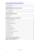
Figure 1 shows the connection location for the
dsPICDEM MCHV-2 Development Board.
FIGURE 1: INTERNAL OP AMP
CONFIGURATION BOARD
Hardware Compatibility
Table 1 provides information on the hardware versions
of the motor control boards that are compatible with this
PIM. Refer to the user's guide for the specific motor
control board for hardware version identification
information.
TABLE 1: HARDWARE COMPATIBILITY
Development Board Part Number Compatible Hardware Version(s)
dsPICDEM™ MCHV Development Board DM330023 Not compatible
dsPICDEM™ MCLV Development Board DM330021 Not compatible
dsPICDEM™ MCSM Development Board DM330022 Not compatible
dsPICDEM™ MCHV-2 Development Board DM330023-2 All revisions
dsPICDEM™ MCLV-2 Development Board DM330021-2 All revisions
Warning:
Do not connect non-isolated oscilloscope probes to the test points on the dsPIC33EP256MC506 Internal Op amp
Motor Control PIM while using the PIM with the dsPICDEM™ MCHV-2 Development Board. Use a high voltage
differential probe rated in excess of 600 VRMS (common mode). Failure to heed this warning could result in hardware
damage.
dsPIC33EP256MC506 Plug-In Module (PIM)
Information Sheet for Internal Op amp Configuration

dsPIC33EP256MC506
DS52062A-page 2 © 2012 Microchip Technology Inc.
Table 2 provides the static mapping between the 100-pin PIM pins and the device pins.
TABLE 2: 64-PIN DEVICE TO 100-PIN PIM MAPPING
Device
Pin # dsPIC33EP256MC506
Device Functional Description PIM Pin # PIM Functional Description Device
Pin # dsPIC33EP256MC506
Device Functional Description PIM Pin # PIM Functional
Description
1TDI/RA7 —Not connected 33 CVREF2O/SDO1/RP20/T1CK/RA4 —Used by Op amp circuit
2RPI46/PWM1H/T3CK/RB14 94 PWM Out – H1 34 SDI1/RPI25/RA9 77 HALLC/INDX/STP_PWM
3RPI47/PWM1L/T5CK/RB15 93 PWM Out – L1 35 SCK1/RPI51/RC3 79 AC input zero cross
4RP118/RG6 84 Switch/UART TX 36 SDA1/RPI52/RC4 69 LIN Fault
5RPI119/RG7 83 Switch 37 SCL1/RPI53/RC5 49 UART RX
6RP120/RG8 76 HALLB/QEB/USB TX 38 VDD 2, 16, 37,
46, 62, 86 N/A
7MCLR 13 Device Master Clear 39 OSC1/CLKI/RC12 63 OSCI
8RPI121/RG9 72 HALLA/QEA/USB RX 40 OSC2/CLKO/RC15 64 OSCO
9 VSS 15, 36,
45, 65, 75 N/A 41 VSS 15, 36,
45, 65, 75 N/A
10 VDD 2, 16, 37,
46, 62, 86 N/A 42 RD8 —Debug test point
11 AN10/RPI28/RA12 35 DC_BUS voltage (scaled) 43 PGED2/ASDA2/RP37/RB5 27 PGED2
12 AN9/RPI27/RA11 25 IA/IPFC current 44 PGEC2/ASCL2/RP38/RB6 26 PGEC2
13 AN0/OA2OUT/RA0 42 V_M2 motor phase voltage 45 RPI58/RC10 61 HOME signal (QEI)
14 AN1/C2IN1+/RA1 22, 41 QEA/IA/V_M1/POT 46 RP39/INT0/RB7 19 PFC Fault/UART TX
15 PGED3/VREF-/AN2/C2IN1-/SS1/RPI32/CTED2/RB0 43 V_M3/IBUS/HALLC 47 RC13 82 General purpose I/O
16 PGEC3/VREF+/AN3/OA1OUT/RPI33/CTED1/RB1 59 Op amp 1 output 48 TCK/CVREF1O/ASCL1/RP40/T4CK/RB8 68 BTN/LINCS
17 PGEC1/AN4/C1IN1+/RPI34/RB2 21 QEB/IB/V_M2 49 TMS/ASDA1/RP41/RB9 78 PFC PWM/CAN RX
18 PGED1/AN5/C1IN1-/RP35/RB3 —Used by Op amp circuit 50 RP54/RC6 47 HALLB/QEB
19 AVDD 30 N/A 51 RP55/RC7 70 BTN/RX
20 AVSS 31 N/A 52 RP56/RC8 88 CAN TX
21 AN6/OA3OUT/C4IN1+/OCFB/RC0 58 Op amp 3 output 53 RD5 60 Debug LED2
22 AN7/C3IN1-/C4IN1-/RC1 —Used by Op amp circuit 54 RD6 1Debug LED1
23 AN8/C3IN1+/U1RTS/BCLK1/FLT3/RC2 20 INDX/POT/V_M3 55 RP57/RC9 87 CAN RX
24 AN11/C1IN2-/U1CTS/FLT4/RC11 24 IB/POT 56 VCAP —Not connected
25 VSS 15, 36,
45, 65, 75 N/A 57 VDD 2, 16, 37,
46, 62, 86 N/A
26 VDD 2, 16, 37,
46, 62, 86 N/A 58 RPI96/RF0 48 HALLC/INDX
27 AN12/C2IN2-/U2RTS/BCLK2/RE12 —Reconstructed motor neutral input 59 RP97/RF1 50 UART TX
28 AN13/C3IN2-/U2CTS/RE13 32, 33 Potentiometer 60 RP42/PWM3H/RB10 3PWM Out – H3
29 AN14/RPI94/RE14 23 IBUS / VBUS 61 RP43/PWM3L/RB11 100 PWM Out – L3
30 AN15/RPI95/RE15 34 General purpose I/O 62 RPI44/PWM2H/RB12 99 PWM Out – H2
31 SDA2/RPI24/RA8 80 HALLA/QEA 63 RPI45/PWM2L/CTPLS/RB13 98 PWM Out – L2
32 FLT32/SCL2/RP36/RB4 18 Overcurrent Fault input 64 TDO/RA10 —Not connected

© 2012 Microchip Technology Inc. DS52062A-page 3
dsPIC33EP256MC506
FIGURE 2: 100-PIN HEADER SCHEMATIC
Z9 84
Z6 81
Z3 78
X2
27 Z24 99
X5
30 Z21 96
X8
33 Z18 93
X11
36 Z15 90
X14
39 Z12 87
X17
42
X20
45
X23
48
W23
23
W20
20
W17
17
W14
14
W11
11
W8
8
W5
5
W2
2
Y3 53
Y6 56
Y9 59
Y12 62
Y15 65
Y18 68
Y21 71
Y24 74
W24
24
W25
25
W21
21
W18
18
W22
22
W19
19
W15
15
W12
12
W16
16
W13
13
W9
9
W6
6
W10
10
W7
7
W3
3
W4
4
W1
1
Z7 82
Z4 79
Z5 80
Y2 52
Y1 51
Y5 55
Y8 58
Y4 54
Y7 57
Y11 61
Y14 64
Y10 60
Y13 63
Y17 67
Y20 70
Y16 66
Y19 69
Y23 73
Y22 72
Y25 75
Z1 76
X1
26
X4
29
X3
28
Z25 100
Z22 97
Z23 98
X7
32
X10
35
X9
34
Z19 94
Z16 91
Z17 92
X13
38
X16
41
X15
40
Z13 88
Z10 85
Z11 86
X19
44
X22
47
X21
46
X25
50
Z8 83
Z2 77
X6
31
X12
37
X18
43
X24
49
Z20 95
Z14 89
U1A
V_M2
V_M1/POT
QEA/IA/V_M1
IA+
V_M3/IBUS
FLT_OUT1
QEB/IB/V_M2
IBUS-
IBUS+
REC_NEUTR
IB+
INDX/POT/V_M3
HALLA/QEA
IBUS/VBUS
GEN2
FAULT FLT_OUT2
IB/POT
VREF_EXT
PWM1H1
PWM1L1
BTN/TX/USBTX
MCLR
HALLA/QEA/USBRX
DC_BUS
IA/IPFC
HALLB/QEB/USBTX
BTN/USBTX
BTN/FAULT/LINCS
GEN1
FAULT_RST
HOME
PGEC3
PGED3
OSCO
OSCI
RX
LINFAULT
VACZ
HALLC/INDX/STP_PWM
PWM1L2
PWM1H2
PWM1L3
PWM1H3
TX
HALLC/INDX
CANRX
DGB_LED2
CANTX
BTN/RX
HALLB/QEB
PFC_PWM
VDD
VDD
VDD
VDD
VDD
AVDD
VDD
DBG_LED1
POT
POT

dsPIC33EP256MC506
DS52062A-page 4 © 2012 Microchip Technology Inc.
FIGURE 3: 64-PIN DEVICE SCHEMATIC
V_M2
V_M1/POT
QEA/IA/V_M1
VREF
IA+
V_M3/IBUS
FLT_OUT1
QEB/IB/V_M2
IBUS-
IBUS+
REC_NEUTR
IB+
INDX/POT/V_M3
HALLA/QEA
IBUS/VBUS
GEN2
VREF
REC_NEUTR
IBUS+
VREF
REC_NEUTR
IBUS+
FAULT
FLT_OUT2 IB/POT
POT
AVDD
VDD
VDD
VDD
RD8
BTN/FAULT/LINCS
GEN1
FAULT_RST
HOME
PGEC3
PGED3
DBG_TP
OSCO
OSCI
RX
LINFAULT
VACZ
HALLC/INDX/STP_PWM
CVREF20
PWM1L2
PWM1H2
PWM1L3
PWM1H3
TX
HALLC/INDX
CANRX
DBG_LED1
DGB_LED2
CANTX
BTN/RX
HALLB/QEB
PFC_PWM
PWM1H1
PWM1L1
BTN/TX/USBTX
MCLR
HALLA/QEA/USBRX
DC_BUS
IA/IPFC
HALLB/QEB/USBTX
BTN/USBTX
0.1 µF
C1
0.1 µF
C2
0.1 µF
C3
0.1 µF
C4
VDD
0.1uF
C6
10 µF
C5
C7 DNP
C8 DNP
C12 DNP
C13 DNP
470pFC9
470pFC14
470pFC16
470pFC17
470pFC19
470pFC11
C20 DNP
1000pF
C10
1000pF
C18
1000pF
C15
1KR3
1KR16 1KR17
1KR211KR20
1KR22 1KR23
1KR4 1KR5
R15
DNP
R6
DNP
R18
DNP
30K
R11
30K
R19
TDI/RA7
1
RPI46/PWM1H/T3CK/RB14
2
RPI47/PWM1L/T5CK/RB15
3
RP118/RG6
4
RPI119/RG7
5
RP120/RG8
6
MCLR
7
RPI121/RG9
8
VSS
9
VDD
10
AN10/RP128/RA12
11
AN9/RP127/RA11
12
AN0/OA2OUT/RA0
13
AN1/C2IN1+/RA1
14
PGED3/VREF-/AN2/C2IN1-/SS1/RP132/CTED2/RB0
15
PGEC3/VREF+/AN3/OA1OUT/RP133/CTED/RB1
16
PGEC1/AN4/C1IN1+/RP134/RB2
17
PGED1/AN5/C1IN1-/RP35/RB3
18
AVDD
19
AVSS
20
AN6/OA3OUT/C4IN1+/OCFB/RC0
21
AN7/C3IN1-/C4IN1-/RC1
22
AN8/C3IN1+/U1RTS/BCLK1/FLT3/RC2
23
AN11/C1IN2-/U1CTS/FLT4/RC11
24
VSS
25
VDD
26
AN12/C2IN2-/U2RTS/BCLK2/RE12
27
AN13/C3IN2-/U2CTS/RE13
28
AN14/RP194/RE14
29
AN15/RP195/RE15
30
SDA2/RP124/RA8
31
FLT32/SCL2/RP36/RB4
32 CVREF20/SDO1/RP20/T1CK/RA4 33
SDI1/RP125/RA9 34
SCK1/RP151/RC3 35
SDA1/RP152/RC4 36
SCL1/RP153/RC5 37
VDD 38
OSC1/CLK1/RC12 39
OSC2/CLKO/RC15 40
VSS 41
RD8 42
PGED2/ASDA2/RP37/RB5 43
PGEC2/ASCL2/RP38/RB6 44
RP158/RC10 45
RP39/INT0/RB7 46
RC13 47
TCK/CVREF10/ASCL1/RP40/T4CK/RB8 48
TMS/ASDA1/RP41/RB9 49
RP54/RC6 50
RP55/RC7 51
RP56/RC8 52
RD5 53
RD6 54
RP57/RC9 55
VCAP 56
VDD 57
RP196/RF0 58
RP97/RF1 59
RP42/PWM3H/RB10 60
RP43/PWM3L/RB11 61
RPI44/PWM2H/RB12 62
RP145/PWM2L/CTPLS/RB13 63
TDO/RA10 64
U1
dsPIC33EP256MC506
30KR24
30KR1
30K
R7
30KR101KR8
2K
R9
* All Resistors are 1%
R30
DNP
R31
DNP
R32
DNP
1KR13 1KR14
R12
DNP
1KR2
VREF_EXT
CVREF20
VREF
R25
0R
R27
DNP
A_GND
DNP
R26
DNP
2K
R28
15K
R29
AVDD

© 2012 Microchip Technology Inc. DS52062A-page 5
dsPIC33EP256MC506
In the schematic shown in Figure 3, resistors R25, R26
and R27 are used to choose the reference voltage
(VREF) from motor control board (VREF_EXT) or
device internal reference (CVREF20) or a simple volt-
age divider (R28-R29), respectively. By default, the
PIM is configured to source the reference voltage from
the motor control board.
Table 3 classifies the passive components according to
their functionality and also quotes the design equations
applicable in each case.
TABLE 3: ANALOG FUNCTIONALITY LISTING
Op amp
#Analog
Function Passive Components Design Equations
1Low Pass Filter R13, R14, R16, R17,
C14, C15, C16
Reference Voltage Bias R10, R11
Voltage Divider R8, R9
Differential Amplifier Input R13, R14, R16, R17
Differential Amplifier Feedback R11
2Low Pass Filter R2, R3, R4, R5,
C9, C10, C11
Reference Voltage Bias R1, R7
Differential Amplifier Input R2, R3, R4, R5
Differential Amplifier Feedback R7
3Low Pass Filter R20, R21, R22, R23,
C17, C18, C19
Reference Voltage Bias R24, R19
Differential Amplifier Input R20, R21, R22, R23
Differential Amplifier Feedback R19
R13 R14 R16 R17 R====
C14 C16 C==
Common mode f-3dB 1
2πRC
---------------
≅
Differential mode f-3dB 1
2π2R()
C
2
----C15
+
⎝⎠
⎛⎞
--------------------------------------------
≅
DifferentialAmplifierGain R11
2R
--------
=
R10 R11=
R2R3R4R5R====
C9C11 C==
Common mode f-3dB 1
2πRC
---------------
≅
Differential mode f-3dB 1
2π2R()
C
2
----C10
+
⎝⎠
⎛⎞
--------------------------------------------
≅
DifferentialAmplifierGain R7
2R
-------
=
R1R7=
R20 R21 R22 R23 R====
C17 C19 C==
Common mode f-3dB 1
2πRC
---------------
≅
Differential mode f-3dB 1
2π2R()
C
2
----C18
+
⎝⎠
⎛⎞
--------------------------------------------
≅
DifferentialAmplifierGain R19
2R
--------
=
R24 R19=

dsPIC33EP256MC506
DS52062A-page 6 © 2012 Microchip Technology Inc.
FIGURE 4: OP AMP CIRCUIT BLOCK DIAGRAM
VREF
IA+
IBUS+
Filter,
Feedback
and Bias
Circuit
14
15
AN1/RA1
AN2/RB0 Op amp 2 AN0/RA0 V_M2
From Shunt
Resistor (IA) +
–
VREF
IBUS-
Filter,
Feedback
and Bias
Circuit
17
18
AN4/RB2
AN5/RB3 Op amp 1 AN3/RB1 FLT_OUT1
From Shunt
Resistor (IBUS) +
–
VREF
IB+
IBUS+
Filter,
Feedback
and Bias
Circuit
23
22
AN8/RC2
AN7/RC1 Op amp 3 AN6/RC0 FLT_OUT2
From Shunt
Resistor (IB) +
–
IBUS-
Voltage
Divider
1k 1k
470pF
1k 1k
1000pF
470pF
Filter, Feedback and Bias Circuit
D
C
30k 30k DNP
E
F
B
A
Differential Amplifier Gain 30kΩ
21kΩ×
--------------------15==
Differential mode f 3dB–1
2π21kΩ×()
470pF
2
----------------1000pF+
⎝⎠
⎛⎞
--------------------------------------------------------------------------------65kHz≅≅
Common mode f 3dB–1
2π1kΩ()470pF()
--------------------------------------------340kHz≅≅
13
16
21
dsPIC33EP256MC506
D
C
D
C
D
C
B
A
B
A
B
A
E
F
E
F
E
F

© 2012 Microchip Technology Inc. DS52062A-page 7
Information contained in this publication regarding device
applications and the like is provided only for your convenience
and may be superseded by updates. It is your responsibility to
ensure that your application meets with your specifications.
MICROCHIP MAKES NO REPRESENTATIONS OR
WARRANTIES OF ANY KIND WHETHER EXPRESS OR
IMPLIED, WRITTEN OR ORAL, STATUTORY OR
OTHERWISE, RELATED TO THE INFORMATION,
INCLUDING BUT NOT LIMITED TO ITS CONDITION,
QUALITY, PERFORMANCE, MERCHANTABILITY OR
FITNESS FOR PURPOSE. Microchip disclaims all liability
arising from this information and its use. Use of Microchip
devices in life support and/or safety applications is entirely at
the buyer’s risk, and the buyer agrees to defend, indemnify and
hold harmless Microchip from any and all damages, claims,
suits, or expenses resulting from such use. No licenses are
conveyed, implicitly or otherwise, under any Microchip
intellectual property rights.
Trademarks
The Microchip name and logo, the Microchip logo, dsPIC,
KEELOQ, KEELOQ logo, MPLAB, PIC, PICmicro, PICSTART,
PIC32 logo, rfPIC and UNI/O are registered trademarks of
Microchip Technology Incorporated in the U.S.A. and other
countries.
FilterLab, Hampshire, HI-TECH C, Linear Active Thermistor,
MXDEV, MXLAB, SEEVAL and The Embedded Control
Solutions Company are registered trademarks of Microchip
Technology Incorporated in the U.S.A.
Analog-for-the-Digital Age, Application Maestro, chipKIT,
chipKIT logo, CodeGuard, dsPICDEM, dsPICDEM.net,
dsPICworks, dsSPEAK, ECAN, ECONOMONITOR,
FanSense, HI-TIDE, In-Circuit Serial Programming, ICSP,
Mindi, MiWi, MPASM, MPLAB Certified logo, MPLIB,
MPLINK, mTouch, Omniscient Code Generation, PICC,
PICC-18, PICDEM, PICDEM.net, PICkit, PICtail, REAL ICE,
rfLAB, Select Mode, Total Endurance, TSHARC,
UniWinDriver, WiperLock and ZENA are trademarks of
Microchip Technology Incorporated in the U.S.A. and other
countries.
SQTP is a service mark of Microchip Technology Incorporated
in the U.S.A.
All other trademarks mentioned herein are property of their
respective companies.
© 2012, Microchip Technology Incorporated, Printed in the
U.S.A., All Rights Reserved.
Printed on recycled paper.
ISBN: 978-1-62076-116-8
Note the following details of the code protection feature on Microchip devices:
• Microchip products meet the specification contained in their particular Microchip Data Sheet.
• Microchip believes that its family of products is one of the most secure families of its kind on the market today, when used in the
intended manner and under normal conditions.
• There are dishonest and possibly illegal methods used to breach the code protection feature. All of these methods, to our
knowledge, require using the Microchip products in a manner outside the operating specifications contained in Microchip’s Data
Sheets. Most likely, the person doing so is engaged in theft of intellectual property.
• Microchip is willing to work with the customer who is concerned about the integrity of their code.
• Neither Microchip nor any other semiconductor manufacturer can guarantee the security of their code. Code protection does not
mean that we are guaranteeing the product as “unbreakable.”
Code protection is constantly evolving. We at Microchip are committed to continuously improving the code protection features of our
products. Attempts to break Microchip’s code protection feature may be a violation of the Digital Millennium Copyright Act. If such acts
allow unauthorized access to your software or other copyrighted work, you may have a right to sue for relief under that Act.
Microchip received ISO/TS-16949:2009 certification for its worldwide
headquarters, design and wafer fabrication facilities in Chandler and
Tempe, Arizona; Gresham, Oregon and design centers in California
and India. The Company’s quality system processes and procedures
are for its PIC® MCUs and dsPIC® DSCs, KEELOQ® code hopping
devices, Serial EEPROMs, microperipherals, nonvolatile memory and
analog products. In addition, Microchip’s quality system for the design
and manufacture of development systems is ISO 9001:2000 certified.
QUALITYMANAGEMENT
S
YSTEM
CERTIFIEDBYDNV
== ISO/TS16949==

DS52062A-page 8 © 2012 Microchip Technology Inc.
AMERICAS
Corporate Office
2355 West Chandler Blvd.
Chandler, AZ 85224-6199
Tel: 480-792-7200
Fax: 480-792-7277
Technical Support:
http://www.microchip.com/
support
Web Address:
www.microchip.com
Atlanta
Duluth, GA
Tel: 678-957-9614
Fax: 678-957-1455
Boston
Westborough, MA
Tel: 774-760-0087
Fax: 774-760-0088
Chicago
Itasca, IL
Tel: 630-285-0071
Fax: 630-285-0075
Cleveland
Independence, OH
Tel: 216-447-0464
Fax: 216-447-0643
Dallas
Addison, TX
Tel: 972-818-7423
Fax: 972-818-2924
Detroit
Farmington Hills, MI
Tel: 248-538-2250
Fax: 248-538-2260
Indianapolis
Noblesville, IN
Tel: 317-773-8323
Fax: 317-773-5453
Los Angeles
Mission Viejo, CA
Tel: 949-462-9523
Fax: 949-462-9608
Santa Clara
Santa Clara, CA
Tel: 408-961-6444
Fax: 408-961-6445
Toronto
Mississauga, Ontario,
Canada
Tel: 905-673-0699
Fax: 905-673-6509
ASIA/PACIFIC
Asia Pacific Office
Suites 3707-14, 37th Floor
Tower 6, The Gateway
Harbour City, Kowloon
Hong Kong
Tel: 852-2401-1200
Fax: 852-2401-3431
Australia - Sydney
Tel: 61-2-9868-6733
Fax: 61-2-9868-6755
China - Beijing
Tel: 86-10-8569-7000
Fax: 86-10-8528-2104
China - Chengdu
Tel: 86-28-8665-5511
Fax: 86-28-8665-7889
China - Chongqing
Tel: 86-23-8980-9588
Fax: 86-23-8980-9500
China - Hangzhou
Tel: 86-571-2819-3187
Fax: 86-571-2819-3189
China - Hong Kong SAR
Tel: 852-2401-1200
Fax: 852-2401-3431
China - Nanjing
Tel: 86-25-8473-2460
Fax: 86-25-8473-2470
China - Qingdao
Tel: 86-532-8502-7355
Fax: 86-532-8502-7205
China - Shanghai
Tel: 86-21-5407-5533
Fax: 86-21-5407-5066
China - Shenyang
Tel: 86-24-2334-2829
Fax: 86-24-2334-2393
China - Shenzhen
Tel: 86-755-8203-2660
Fax: 86-755-8203-1760
China - Wuhan
Tel: 86-27-5980-5300
Fax: 86-27-5980-5118
China - Xian
Tel: 86-29-8833-7252
Fax: 86-29-8833-7256
China - Xiamen
Tel: 86-592-2388138
Fax: 86-592-2388130
China - Zhuhai
Tel: 86-756-3210040
Fax: 86-756-3210049
ASIA/PACIFIC
India - Bangalore
Tel: 91-80-3090-4444
Fax: 91-80-3090-4123
India - New Delhi
Tel: 91-11-4160-8631
Fax: 91-11-4160-8632
India - Pune
Tel: 91-20-2566-1512
Fax: 91-20-2566-1513
Japan - Osaka
Tel: 81-66-152-7160
Fax: 81-66-152-9310
Japan - Yokohama
Tel: 81-45-471- 6166
Fax: 81-45-471-6122
Korea - Daegu
Tel: 82-53-744-4301
Fax: 82-53-744-4302
Korea - Seoul
Tel: 82-2-554-7200
Fax: 82-2-558-5932 or
82-2-558-5934
Malaysia - Kuala Lumpur
Tel: 60-3-6201-9857
Fax: 60-3-6201-9859
Malaysia - Penang
Tel: 60-4-227-8870
Fax: 60-4-227-4068
Philippines - Manila
Tel: 63-2-634-9065
Fax: 63-2-634-9069
Singapore
Tel: 65-6334-8870
Fax: 65-6334-8850
Taiwan - Hsin Chu
Tel: 886-3-5778-366
Fax: 886-3-5770-955
Taiwan - Kaohsiung
Tel: 886-7-536-4818
Fax: 886-7-330-9305
Taiwan - Taipei
Tel: 886-2-2500-6610
Fax: 886-2-2508-0102
Thailand - Bangkok
Tel: 66-2-694-1351
Fax: 66-2-694-1350
EUROPE
Austria - Wels
Tel: 43-7242-2244-39
Fax: 43-7242-2244-393
Denmark - Copenhagen
Tel: 45-4450-2828
Fax: 45-4485-2829
France - Paris
Tel: 33-1-69-53-63-20
Fax: 33-1-69-30-90-79
Germany - Munich
Tel: 49-89-627-144-0
Fax: 49-89-627-144-44
Italy - Milan
Tel: 39-0331-742611
Fax: 39-0331-466781
Netherlands - Drunen
Tel: 31-416-690399
Fax: 31-416-690340
Spain - Madrid
Tel: 34-91-708-08-90
Fax: 34-91-708-08-91
UK - Wokingham
Tel: 44-118-921-5869
Fax: 44-118-921-5820
Worldwide Sales and Service
11/29/11
/