
Vess A6600/A7600 (VES0603)
Vess A6800/A7800 (VES0604)
Storage Appliance for
Video Surveillance
Quick Start Guide
Version 1.2
© 2023 Promise Technology. All Rights Reserved.

Warning
This is a Class A product. In a domestic
environment this product may cause radio
interference in which case the user may be
required to take adequate measures.
Warning
The electronic components within the enclosure
are sensitive to damage from Electro-Static
Discharge (ESD). Observe appropriate precautions
at all times when handling the Vess A7000 or its
subassemblies.
Warning
Turn off the power and disconnect the power cord
before servicing this device.
ii
Promise Technology


About this guide .......................................................................................... 1
introduction ................................................................................................ 1
Models included in this guide ..................................................................... 1
Front PAnel ................................................................................................ 2
reAr PAnel ................................................................................................. 4
Vess A7600 / Vess A7800 ReAR PAnel oVeRView ....................................... 4
Vess A6600 / Vess A6800 ReAR PAnel oVeRView ....................................... 6
secure cover .............................................................................................. 8
instAlling the coVeR ................................................................................... 9
setuP tAsks ........................................................................................... 10
tAsk 1: unPAcking ................................................................................... 10
PAcking list ............................................................................................ 10
tAsk 2: Mounting in A RAck ................................................................... 11
tAsk 3: instAlling disk dRiVes ............................................................... 15
drive slot numbering ............................................................................... 15
removing the drive cArrier ...................................................................... 17
instAlling 3.5” disk drive in the cArrier .................................................. 19
instAlling 2.5” disk drive in the cArrier .................................................. 20
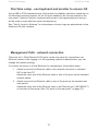
tAsk 4: MAnAgeMent i/o connections .................................................. 21
FiRst tiMe setuP - use keyboARd And MonitoR to Access os ...................... 22
MAnAgeMent PAth - netwoRk connection .................................................. 22
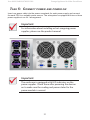
tAsk 5: connect PoweR And PoweR on ................................................. 23
PoweR on................................................................................................ 24
FRont PAnel led behAVioR ....................................................................... 26
disk dRiVe leds ...................................................................................... 26
Psu leds .............................................................................................. 27
ReAR PAnel led behAVioR ......................................................................... 27
tAsk 6: login to windows .................................................................... 28
Promise Technology
iv
Quick Installation Guide

tAsk 7: cReAte logicAl dRiVes ..............................................................29
logging into PRoMise MAnAgeMent gui ..................................................29
choose A lAnguAge - PRoMise MAnAgeMent gui ......................................30
creAting Your logicAl drives ..................................................................31
systeM shutdown ...................................................................................37
technicAl suPPort .................................................................................38
v
Vess A3120 Storage Appliance for Video Surveillance

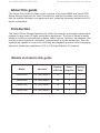
About this guide
This Quick Start Guide provides a brief overview of the Vess A6000 and Vess A7000
Series Storage Appliance for Video Surveillance, and then provides instructions to in-
stall the system hardware in an equipment rack, make the necessary network and I/O
device connections.
Model Interface Number
of Drives
Power
Supplies
Cooling
Units
Vess A6600 2 x 1000 BASE-T 16 2 2
Vess A6800 2 x 1000 BASE-T 24 3 2
Vess A7600 2 x 1000 BASE-T 16 2 2
Vess A7800 2 x 1000 BASE-T 24 3 2
Models included in this guide
Introduction
The Vess A Series Storage Appliance for Video Surveillance is specially engineered for
medium to large scale IP video surveillance deployment. The Vess A Series is ideally
suited for continuous surveillance in banks, malls, casinos, factories, warehouses, and
similarly sized commercial, residential, governmental or private enterprises. The sub-
systems are capable of continuous recording and playback operation without dropping
frames for networked installations of 32 to 100 High-Denition IP cameras.
1
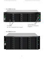
Vess A6600 /A6800/A7600/A7800 Storage Appliance for Video Surveillance

Drive carriers
See “Task 3: Installing Disk Drives” on page 15
Power and Status LEDs
See “Front panel LED behavior”
on page 26
Vess A7600 front view
Vess A7800 front view
The front panel hardware components on the Vess A6600, Vess A6800 are similar
to the Vess A7600 and Vess A7800. The differences are cosmetic, for the purpose
of easy identication. The Vess A6600 and Vess A6800 use a different style of disk
carrier and feature black colored front panel, where the Vess A7600 and Vess A7800
have a silver front panel.
A defective drive may be replaced without interruption of data availability to the host
computer. If so congured, a hot spare drive will automatically replace a failed drive,
securing the fault-tolerant integrity of the logical drive. The self-contained hardware-
based RAID logical drive provides maximum performance in a compact external enclo-
sure.
Front Panel
2
Promise Technology Quick Start Guide


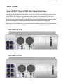
Vess A7800 rear view
Vess A7600 rear view
Rear Panel
Vess A7600 / Vess A7800 Rear Panel Overview
The rear panel hardware components on the Vess A7800 are nearly the same as the
Vess A7600. This is where you connect power cables, I/O connections, IPMI port,
audio out/in, video (VGA), USB serial ports, COM1 (serial port) and SAS port Backend
Controller card. Both enclosures include PCIe slots for added system versatility. See
the Product Manual for details about what PCIe components are supported.
Please see more detailed close-up view of power supplies and controller components
in the illustration on the next page.
4
Promise Technology Quick Start Guide

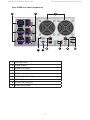
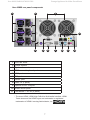
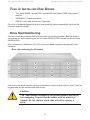
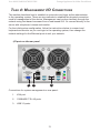
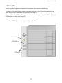
Vess A7800 rear panel components
1 2
4 5 6 7 8 9
3
1PSU fan vents
2Power inserts
3System fan vents
4Serial port (COM1)
5VGA port
61000BASE-T RJ-45 (2 ports)
7USB 3.0 (4 ports)
8RJ-45 IPMI LAN port
9Audio In/Out ports
5
Vess A6600 /A6800/A7600/A7800 Storage Appliance for Video Surveillance

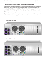
Vess A6600 rear view
Vess A6800 rear view
Vess A6600 / Vess A6800 Rear Panel Overview
The rear panel hardware components on the Vess A6800 are nearly the same as the
Vess A6600. This is where you connect power cables, I/O connections, audio out/
in, video (VGA), USB ports, and SAS port Backend Controller card. Both enclosures
include PCIe slots for adding additional hardware such as an RS-232 console port
(available for purchase from Promise). See the Product Manual for details about what
PCIe components are supported.
Please see more detailed close-up view of power supplies and controller components
in the illustration on the next page.
6
Promise Technology Quick Start Guide

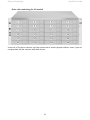
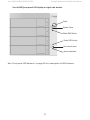
Vess A6800 rear panel components
1 2
10
11
3
4 6 7 95 8
1PSU fan vents
2Power inserts
3System fan vents
4PS/2 mouse/keyboard port
5VGA port
6DVI port
7HDMI* port
8USB 3.0 (4 ports)
9Optical SPDIF Out port
10 Audio In/Out ports
11 1000BASE-T RJ-45 (2 ports)
* The terms HDMI, HDMI High-Denition Multimedia Interface, HDMI
Trade dress and the HDMI Logos are trademarks or registered
trademarks of HDMI Licensing Administrator, Inc.
7
Vess A6600 /A6800/A7600/A7800 Storage Appliance for Video Surveillance

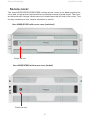
Vess A6600/A7600 with secure cover (unlocked)
Tubular cam lock
Vess A6800/A7800 with secure cover (locked)
Tubular cam lock
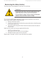
Secure cover
The Vess A6600/A6800/A7600/A7800 include secure covers to for better physical se-
curity and to help prevent unintended or accidental removal of hard drives. The cover
are secured with a single tubular cam lock located near the left side of the cover. Turn
the key clockwise to lock, counter clockwise to unlock.
8
Promise Technology Quick Start Guide

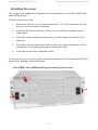
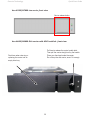
Vess A7800 / Vess A6800 installing and removing secure cover
Installing the cover
The secure cover hardware is operated in the same fashion on the Vess A7600 and
Vess A6600 models.
To attach the secure cover:
1. Make sure the lock is in the unlocked position. To unlock, insert the key into
the lock and turn counter clockwise.
2. Insert the tab on the right side of the cover into the slot receptacle on the
right handle.
3. Place the cover in position and push in the latch release (to the left of the
keyhole).
4. Push the cover into position so that the tab on the right side inserts into the
receptacle on the right handle when releasing the latch.
5. Insert the key and turn clockwise to lock.
To remove the cover, unlock it, press the latch release on the left side and pull the left
end out rst, holding it with both hands.
9
Vess A6600 /A6800/A7600/A7800 Storage Appliance for Video Surveillance

Task 1: Unpacking
Note that the two models are nearly identical, except for the number of disk drive bays.
Packing List
The box contains the following items:
• One of the following Vess storage appliances:
• Vess A6600
• Vess A6800
• Vess A7600
• Vess A7800
• Screws for disk drives
• Three 1.5m (4.9 ft) power cords
• Front panel bezel cover
• (Optional) Sliding rail assembly for rack mounting
This item is optional. Please ask your reseller for purchasing details.
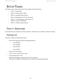
Setup taSkS
The basic setup tasks described in the guide are the following:
• “Task 1: Unpacking”
• “Task 2: Mounting in a Rack”
• “Task 3: Installing Disk Drives”
• “Task 4: Management I/O Connections”
• “Task 5: Connect power and power on”
• “Task 6: Login to Windows”
• “Task 7: Create Logical Drives”
10
Promise Technology Quick Start Guide

Task 2: MoUnTing in a Rack
The instructions here apply to 3U 16-bay models, Vess A7600 and Vess A6600 , as
well as the 4U 24-bay models, Vess A7800 and Vess A6800.
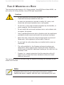
Cautions
* Do not populate any enclosure hardware with hard drives until
it has been securely installed in the rack.
* At least two persons are required to safely lift, place, and
attach the enclosure hardware into a rack system.
* Do not lift or move the enclosure hardware by the handles, or
power supplies. Hold the system itself.
* Do not install the enclosure hardware into a rack without rails
to support the system.
* Only a qualied technician who is familiar with the installation
procedure should mount and install the enclosure hardware.
* Mount the rails to the rack using the appropriate screws and
ange nuts, fully tightened, at each end of the rail.
* Do not load the rails unless they are installed with screws as
instructed.
* The rails available for the Promise enclosure hardware are
designed to safely support that Promise enclosure hardware
when properly installed. Additional loading on the rails is at the
customer’s risk.
* Promise, Inc. cannot guarantee that the mounting rails will
support your Promise enclosure hardware unless you install
them as instructed.
The enclosure installs to the rack using the optional mounting rails available for pur-
chase from Promise.
Note
To lighten the enclosure, you can remove the power supplies.
Replace the power supplies after the unit is mounted in your rack.
11
Vess A6600 /A6800/A7600/A7800 Storage Appliance for Video Surveillance

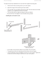
To install the enclosure hardware into a rack with the supplied mounting rails:
1. Check the t of the mounting rails in your rack system.
2. Adjust the length of the mounting rails as needed.
• The rear half of the rail slides inside the front half. The rail halves are riveted
together, so no adjustment screws are needed.
• The front-left and front-right mounting rail ends are labeled.
• Be sure the front rail support is on the bottom facing inward.
Installing the rails onto the rack
• All rail ends, front and rear, attach at the outside of the rack posts.
• The guide pins at the rail ends align with the holes in the rack posts.
• Use the attaching screws and ange nuts from your rack system. Tighten the
screws and nuts according to instructions for your rack system.
12
Promise Technology Quick Start Guide
Support ange on the
front end of each rail
Front right label
Front left label
Guide pins on rails align with
holes in the rack post

Rail ends aach to the outside of each post
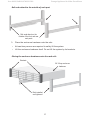
3. Place the enclosure hardware onto the rails.
• At least two persons are required to safely lift the system.
• Lift the enclosure hardware itself. Do not lift the system by its brackets.
Placing the enclosure hardware onto the rack rails
13
Vess A6600 /A6800/A7600/A7800 Storage Appliance for Video Surveillance
Rail ends attach on the
outside of the front and rear
rack posts
Rails installed
and tightened
Brackets
3U 16-bay enclosure
hardware

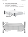
4. Secure the enclosure hardware or to the rack.
• The unit attaches to the rack posts using the included screws and ange nuts.
One screw each side, in the upper hole only.
• Use the attaching screws and ange nuts that came with the enclosure
hardware.
Secure to rack
System installed in rack
14
Promise Technology Quick Start Guide
Screws and ange nuts
attach the enclosure
hardware to the rack
posts
Handles mount outside
the rack post
Mounting rails mount
outside the rack post
Vertical rack post

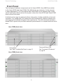
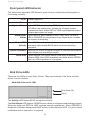
Drive slot numbering for 3U models
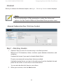
Task 3: insTalling Disk DRives
The Vess A6600, Vess A7600, Vess A6800 and Vess A7800 subsystems
support:
• SATA/SAS 3.5-inch hard disks
• SAS 2.5-inch hard disk drives (Optional)
For a list of supported physical drives, download the latest compatibility list from the
Promise support website.
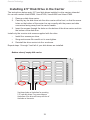
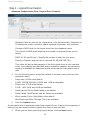
Drive Slot Numbering
You can install any suitable disk drive into any slot in the enclosure. See the illustra-
tions below for slot numbering on the 3U Vess A6600 /A7600, as well as the 4U Vess
A6800/A7800.
Slot numbering is reected in the GUI of the web-based system management user
interface.
Insert all of the drive carriers into the enclosure to ensure proper airow, even if you do
not populate all the carriers with disk drives.
Caution
The Vess models included in this guide support disk drive
hot-swapping. To avoid hand contact with an electrical
hazard, do not remove more than one drive carrier a
time.
15
Vess A6600 /A6800/A7600/A7800 Storage Appliance for Video Surveillance
Page is loading ...
Page is loading ...
Page is loading ...
Page is loading ...
Page is loading ...
Page is loading ...
Page is loading ...
Page is loading ...
Page is loading ...
Page is loading ...
Page is loading ...
Page is loading ...
Page is loading ...
Page is loading ...
Page is loading ...
Page is loading ...
Page is loading ...
Page is loading ...
Page is loading ...
Page is loading ...
Page is loading ...
Page is loading ...
Page is loading ...
-
 1
1
-
 2
2
-
 3
3
-
 4
4
-
 5
5
-
 6
6
-
 7
7
-
 8
8
-
 9
9
-
 10
10
-
 11
11
-
 12
12
-
 13
13
-
 14
14
-
 15
15
-
 16
16
-
 17
17
-
 18
18
-
 19
19
-
 20
20
-
 21
21
-
 22
22
-
 23
23
-
 24
24
-
 25
25
-
 26
26
-
 27
27
-
 28
28
-
 29
29
-
 30
30
-
 31
31
-
 32
32
-
 33
33
-
 34
34
-
 35
35
-
 36
36
-
 37
37
-
 38
38
-
 39
39
-
 40
40
-
 41
41
-
 42
42
-
 43
43


Promise Technology a7600 Quick start guide
- Type
- Quick start guide
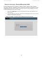
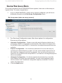
Ask a question and I''ll find the answer in the document
Finding information in a document is now easier with AI
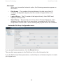
Related papers
-
Promise Technology A3340P Quick start guide
-
Promise Technology A8020 Quick start guide
-
-
-
-
 Vess A2600S User manual
-
Promise Technology VSky A1100 User manual
-
Promise Technology F40VA2600000013 Datasheet
-
-

Other documents
-
Sony SASW5 User manual
-
Hyundai IONIQ ELECTRIC Quick Reference Manual
-
-
-
-
-
-
artisan 99881 User manual
-
-
Lenovo IdeaTab A Series IdeaTab A7600 Owner's manual