Hoover F5837-900 Owner's manual

Category
Scrubber
Type
Owner's manual
SUPREME
DELUXE
ULTRA
SteamVac TMWith Attached
Tools And Automatic Tool
Conversion
SteamVacs with the automatic tool conversion
feature were first introduced in mid-1997. Fig. 1
Characteristics of the three types:
Supreme: No rotating brushes
Deluxe: Five rotating brushes (for carpet only).
Ultra: Five rotating brushes for carpet and a
powered hand nozzle for upholstery.
These are the third generation of Steam Vats made
by Hoover for the domestic market.
5 OUNCES/
15Oral
Easy,One-handed
tankremoval
liJ
All models have:
1 gallon tanks, solution and recovery
8 foot hoses
Quick cord release (back of handle)
Tool/floor mode indicator Fig. 2
Automatic tool conversion
16 oz. pre-cleaner-spray bottle
16 oz. carpet/upholstery detergent
Bare floor cleaning tool, fits front of nozzle. Fig. 3
Upholstery nozzle
1 Speed motor
Measuring eup/eap on solution tank.Fig. 4
Over flow float in recovery tank
Foot operated on and off switch
One handed recovery tank removal. Fig. 5
10/97
TURBINE _-
BRUSIt BLOCK
J._ E:t
ELECTRICAL SYSTEM
Deluxe and Ultra models have 5 mlcllocking rotating
brushes. Fig. 6
Tile brushes are driven by an air pOWeled turbine
Fig. 7
Rotation of tile brush can be viewed though a cleai
cover on the hood. The Speed of the brush depends
on air flow and is adjustable for Lo or Hi rotation or
can be turned off completely as might be desired
when cleaning bare floors. Fig. 8
There are 3 major systems in Steam Vacs:
1. Electrical
2. Distribution
3. Recovery
The Electrical System - Fig. 9 consists of the
power supply cord, motor and on/off switch. Close
the switch, the motor runs and provides suction for
recovery at the floor or the upholstery tool. It also
generates air flow to drive the turbine to rotate the
brushes at the floor and in the powere d wand plus
drive the pump to force solution to the upholstery
tool.
The Distribution System - Fig. 10 When the solu-
tion tank is placed on the unit, a valve in the tank
opens and fills the reservoir and the tube leading to
the pump. With the unit turned on and the handle in
the upright position, the pump runs and sends water
to the wand for above the floor cleaning Fig. 10A
SUN TEA VALVE
RESERVOIR
I0197
DISTRIBUTION SYSTEM
CAP
SOLUTION
,TANK
POPPET
PLUNGER
/SLIDE
VALVE
__ MOTOR
PUMP
_TURBINE
MOTOR
)
ROTATING
BRUSHES
When the handle is lowered to tile operating positiot,
the pump shuts off and the floor brushes (5) start to
rotate (unless turned off manually) Fig. 10B
When the trigger on the handle is depressed, a solu-
tion valve in tile reservoir is opened and water flows.
to the rotating brushes.
Tile Recovery System. Recovery from tile floor is
shown in Fig. 11 With the handle in the operating
position, the pump is off and the valve to the tools
closed. All suction is at the floor nozzle.
Recovery at the upholstery tool is shown in Fig. 12.
With the handle in the storage position the pump
runs, and the valve to the floor is closed diverting all
suction to the upholstery tool.
Key components of the SteamVac Ultra are shown ir
the cut away views on the next page.
Refer to the Hoover Service Manual for repair proce
dures and the Microfiche Parts Catalog, purple head-
er for spare parts.
TANK
RECOVERY
TANK LID
MOTOR
HOSE
MOTOR
DIRTY CLEAN
AIR - AIR
WATER
FRONT
FLOOR
VALVE
DIRTY CLEAN
AIR - AIR
WATER
PUMP
FLOOR
10/97
HOSE
SOIM_ON TANK
MEASURING
CI_/CAP
SOLI.rrION
TRIGGER
CLEAN
TANK
HANDLE
RECOVERYTANK
HANDLE
TANK
SOLUTION
CONTROL
ROD
BAREH.f)OR
TOOL
PUMP
BRUSH BLOCK
RESERVOIR
CORD
HOOK
ON/OFF PEDAL
10/97
FROM
PUMP
FROM
_-_ PUMP
10/9"/
SERVICE INSTRUCTIONS
CARPET CLEANING MACHINE
STEAMVAC
Service Support 10/97
Latch R H
Svatch Button
Duct
I
I
Seal
Hose
I
Actuator Arm
Motor Cover /
Valve Assembly
Seal
Motor
w
Seal
Switch
Pedal
Attachment
Cord
Brush Bloct( Assembly
Whee_
Hand_P°wered Tool_
Tool Holder
Upper Control Rod
Lower SWitChRod
//
S_alo Relief
Lower Handle
SolutionTube
Cover
Float
, Trigger
Recovery Tank Lid
Recovery Tank
Foam F_ter
I. General
The SteamVac TM with Automated Tool
Conversion is a self contained extractor designed
for deep cleaning of carpet and rugs
These models feature the Automated Tool
Conversion actuated by the handle movement.
Mid line models include 5 rotating brushes for
carpet and bare floor agitation. While top end
models also include an air driven hand nozzle.
This instruction deals with top of the line models.
Instructions that pertain to low end models will be
noted.
II. Operation
The units are controlled by the on/off pedal
located on the LH. side.
ON/OFF
PEDAL
Solution is gravity fed to the floor from the
solution tank through the reservoir assembly to
the distributor/brushes.
ROTATING
BRUSHES
CLEAN SOLUTION
The reservoir is opened by actuating the trigger
in the handle.
Suction is directed to the floor through the smoke
colored nozzle and air duct. The suction air is
then drawn up through the valve and into the
recovery tank where the air and water are
separated, A float and foam filter prevent the
recovery tank from being overfilled.
The pump operates on the suction from the
motor. Suction is directed to the pump through
the pump duct (an integral part of the mainbody),
and is completed at the valve which is actuated
by raising the handle into the upright position.
The pump has a constant flow of solution from
the solution tank through the reservoir assembly.
The five rotating brushes are driven by a turbine,
which operates on the suction from the motor.
The recovery tank can be unlatched by rotating
the handle 90° and lifting out of position. To
empty tank continue rotating handle an additional
90° and lift lid from tank.
The Automatic Tool Conversion uses a valve
which diverts the suction from the nozzle to the
hose when the handle is placed in the upright
position.
III. Disassembly
A. Solution Tank
To remove, unlatch and pull tank assembly out of
position as illustrated (Fig. 1).
HANDLE
Fig. 1
Replaceable components of the tank assembly,
cap gasket and poppet valve.
B. Cap Assembly
1. Twist off to remove (Fig. 2)
Fig. 2
2. Slide gasket offto replace (Rib on gasket
faces toward cap).
C. Poppet Valve
1. Insert screwdriver through tank opening and
push valve until it snaps out of seat. (Fig. 3)
Fig. 3
2. Work valve stem out of tank from underneath.
3. The spring, brass washer and valve seal will
stay trapped in the valve seat. Remove through
tank opening.
Note position in Fig 3A.
Fig. 3A
SPRING.-._
WASHER7_
VALVESE*L--C
VALVE STEM -_
The cupped end of the valve seal faces
downward upon reassembly.
To reassemble valve:
1. Slide valve assembly into valve seat through
opening in bottom of tank (Fig. 4). Use a small
amount of soap on seal to ease assembly.
/"
2. With small screwdriver, work rubber washer
into housing (Fig. 5).
3. Continue to slide shaft in until it stops.
4. Valve should spring open and closed when
fully seated.
D. Upper Handle Assembly
1. Removetwo bolts and slide handle off (Fig.6)
Fig. 6
The upper handle is replaced as an assembly.
To replace upper handle rod:
Ultra Models
1. Remove Powered Hand Tool, (Note:
Powered Hand Tool door can be removed by
opening until door snaps off of hinges).
2. Remove tool holder Fig. 7 by snapping out of
position.
Fig. 7
3, Upper handle rod may then be removed by
twisting "jiggling" out of position.
Note: To reposition rod slide up and into handle
with fin labeled "Front" facing the front of the
cleaner. Rod will latch into position.
For models other than those with the Powered
Hand Tool, steps 1 and 2 are omitted.
E. Recovery Tank
1. Release handle to lowest position, (R.H.
Pedal).
2. Rotate tank handle 90° upward and lift out of
position (Fig. 8).
J
Fig. 8
3. To remove lid assem, rotate handle an
additional 90 ° and lift lid from tank.
The lid is carried in service as an assembly that
includes the lid, float retainer, float, and tank
filter.
F. Recovery Tank Duct
1. Remove (3) screws (Fig. 9) and lift out of
)osition.
J
i
Fig. 9
G. Hood
1. Remove agitator speed actuator button.
2. Remove (2) screws (Fig. 10).
Screw
_crew
Fig. 10
3. Carefully pry inward on rear panels of hood to
release (Fig. 11).
Fig. 11
Note: On Ultra Models or models with outer flaps
on hood, flex hood to clear tab on inside of main
body. Hint: Start on same side as standpipe.
4. Pivot hood forward out of position.
H. Hose
1. Hose Connection
a. Flex tab (Fig. 12) to free hose connection to
valve.
Fig. 12
2. Hose Strain Relief
a. Release tab by pushing up and in on lower
tab and then release upper tab to slip hose clear
from handle (Fig. 13).
Fig. 13
I. Hose Service
The hose is replaced as an assembly. To service
grip end:
1. Remove the two screws in the hand grip and
remove cover.
2. Depress the nozzle/valve assembly and
unlatch the trigger. The nozzle/valve assembly is
spring loaded. ( Fig. 14)
Fig. 14
J. Valve Lever
1. Remove screw while holding spring in position.
Note position of spring before removing (Fig. 15)
2. Slide control arm off of valve and release from
lever and spring.
3. Remove turbine control arm and spring
assem by depressing tab on turbine (Fig. 16).
Fig. 16
4. Lift lever slightly and slide forward until lever
is free from unit.
5. Slide actuator arm forward off of pump.
K. Turbine (Deluxe and Ultra Models Only)
The turbine will be replaced as a turbine
assembly complete.
1. Remove (2) screws from bottom (Fig. 17).
I Screw
,_* Screw
Fig. 15 Fig. 17
2. Remove (2)screws located at front of turbine.
3. Disconnect hose from turbine and lift out of
position.
K. Pump
1. Remove (1) screw located on pump
doghouse.
2. Release tab with flat blade screwdriver from
bottom of unit (Fig. 18).
Fig. 18
3. Disconnect hoses from pump.
L. Motor CoverNalve Assembly
1. Remove standpipe seal.
2. Remove (6) screws (Fig. 19)
3. To lift out of position flex outer walls of main
body to clear tabs.
4. Feed tubes through motor cover and remove.
M. Motor
1. Remove hood.
2. Remove recovery tank duct.
3. Remove hose connection at valve.
4. Remove valve lever.
5. Remove turbine assembly.
6. Remove motor cover/valve assembly.
7. Disconnect all lead wires.
8. Lift motor out of position.
Note: Motor is replaced as an assembly only.
N. Attachment Cord
1. Disconnect all lead wires.
2. Remove strain relief from underneath unit by
squeezing tabs and pushing through housing.
Note: Upon reassembly, route cord as shown in
Fig. 20. Also, it is very important to reconnect
the ground lead.
Fig. 19 Fig. 20
O. Brush Block Assembly (Deluxe/Ultra
Models)
To remove brush block assembly simply squeeze
block at tabs shown in Fig. 18 and slip brush
block assembly out of position. To reinstall brush
block assembly align slides on sides of block with
slots in main body and snap brush block
assembly back into position.
P. Handle Release Lever
The RH trunnion traps the handle release lever.
Slide lever inward then up to remove. (Fig. 21)
Fig. 21
Q. SwitchlSwitch Pedal
1. The L.H. trunnion houses the on/off switch
and traps the switch lever. (Fig. 22)
TRUNNION
SWITCH
SWITCH
2. Disconnect leads and snap switch out of
_osition.
3. The switch pedal can be removed once the
trunnion is lifted.
R. Handle Cover
1. Remove upper handle.
2. Release two tabs and lift cover off. (Fig. 23)
Fig. 23
S. Lower Rod
1. Trapped in place by handle cover. Lift out to
remove. (Fig. 24)
:7.
Fig. 22 Fig. 24
T. Reservoir Assembly
1. Release two clips and remove from cradle in
lower handle (Fig. 25)
Fig. 25
The reservoir is replaced as an assembly which
does not include tubing.
The reservoir assembly can be inspected by
removing the diaphragm valve and checking the
chamber valve (Fig. 26).
toremove __ /
t
Fig. 26
Note: Tubing is available in service. Pump
tubing is 3/8" ID. All other is 1/4" ID.
Note tubing routing through motor cover for
reassembly.
U. Motor Seal
The motor seal is positioned below the motor as
shown. (Fig. 27)
Fig. 27
V. Standpipe Seal
1. Press fit to standpipe (Fig. 28).
Fig. 28
W. Rear Wheel
1. Remove "E" clip and slide wheel shaft out of
housing. (Fig. 29)
F MAIN _)OY
Fig. 29
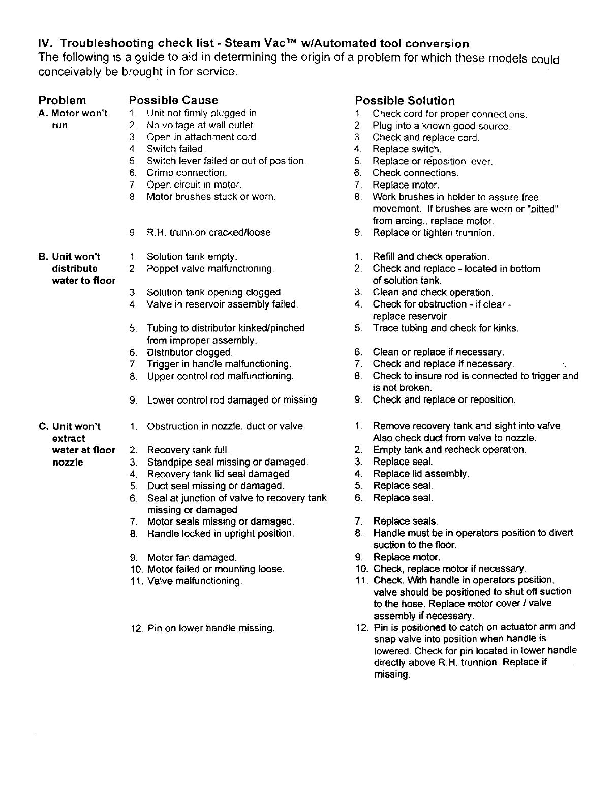
IV. Troubleshooting check list - Steam Vac TM w/Automated tool conversion
The following is a guide to aid in determining the origin of a problem for which these models could
conceivably be brought in for service.
Problem
A. Motor won't
run
Possible Cause
1 Unit not firmly plugged in
2. No voltage at wall outlet.
3 Open in attachment cord
4 Switch failed
5. Switch lever failed or out of position
6. Crimp connection.
7. Open circuit in motor.
8. Motor brushes stuck or worn.
9. R.H. trunnion cracked/loose.
Possible Solution
1 Check cord for proper connections.
2 Plug into a known good source
3 Check and replace cord.
4. Replace switch.
5. Replace or reposition lever.
6. Check connections.
7. Replace motor.
8 Work brushes in holder to assure free
movement. If brushes are worn or "pitted"
from arcing., replace motor.
9. Replace or tighten trunnion.
B. Unit won't
distribute
water to floor
1 Solution tank empty.
2. Poppet valve malfunctioning.
3. Solution tank opening clogged.
4 Valve in reservoir assembly failed.
5. Tubing to distributor kinked/pinched
from improper assembly.
6. Distributor clogged.
7. Trigger in handle malfunctioning.
8. Upper control rod malfunctioning.
9. Lower control roddamaged or missing
1. Refill and check operation.
2. Check and replace - located in bottom
of solution tank.
3. Clean and check operation.
4. Check for obstruction - if clear -
replace reservoir.
5. Trace tubing and check for kinks.
6. Clean or replace if necessary.
7. Check and replace if necessary.
8. Check to insure rod is connected to trigger and
is not broken.
9. Check and replace or reposition.
C, Unit won't
extract
water at floor
nozzle
1. Obstruction in nozzle, duct or valve
2. Recovery tank full
3. Standpipe seal missing or damaged.
4. Recovery tank lid seal damaged.
5. Duct seal missing or damaged.
6. Seal at junction of valve to recovery tank
missing or damaged
7. Motor seals missing or damaged.
8. Handle locked in upright position.
9. Motor fan damaged.
10. Motor failed or mounting loose.
11. Valve malfunctioning.
12. Pin on lower handle missing.
1. Remove recovery tank and sight intovalve.
Also check duct from valve to nozzle.
2. Empty tank and recheck operation.
3. Replace seal.
4. Replace lid assembly.
5. Replace seat.
6. Replace seal.
7. Replace seals.
8. Handle mustbe in operators position to divert
suction tothe floor.
9. Replace motor.
10. Check, replace motor ifnecessary.
11. Check. With handle inoperators position,
valve shouldbe positionedto shut off suction
to the hose. Replace motorcover / valve
assembly if necessary.
12. Pin is positionedto catch on actuator arm and
snap valve intopositionwhen handle is
lowered. Check for pin located in lower handle
directly above R.H. trunnion. Replace if
missing.
IV. Troubleshooting check list - Steam Vac TM wlAutomated tool conversion
The following is a guide to aid in determining the origin of a problem for which these models could
conceivably be brought in for service.
Problem
Possible Cause
Possible Solution
D. Unit won't 1 Solution tank empty
pump. 2 Poppet valve malfunctioning.
(no spray
from hose) 3 Solution tank opening clogged
4 Handle not locked into upright position
5 Reservoir assembly clogged
6. Tubing to pump or from pump to solution
hose coupler kinked.
7. Pump air intake duct clogged.
8. Pump failed.
9. Actuator Arm malfunctioning.
10. Solution hose to wand clogged.
11. Solution hose to wand damaged.
12. Valve in hose grip failed.
1 Refill and check operation
2 Check and replace - located in bottom
of solution tank.
3 Clean and check operation
4. Raise handle and check operation
5 Check and clean or replace
6 Trace tubing and check for kinks -
7. Clean and check operation.
8 Check to insure pump is securely mounted
and that suction air is present at mounting
point. Replace pump if failed,
9. The actuator arm connects to the valve crank
arm and is forced forward when the handle is
raised to the upright position. This exposes the
pump inlet.
10. Solution hose is routed inside of the suction
hose. Attempt to flush hose if clogged,
11. Replace hose assembly.
12. Replace wand / valve assembly
E. Brushes 1. Turbine switch in off position.
will not 2. Brush block jammed.
run, 3. Drive pin on center brush broken.
4. Spring on turbine arm broken or
missing,
5. Actuator arm on turbine broken. 5.
6. Air flow to or from turbine clogged. 6.
7. Cleaning indicator not showing "floor cleaning" 7.
1. Turn on turbine.
2. Remove object causing jam.
3. Replace brush block assembly.
4. Replace spring.
8. Turbine failed.
1. Handle not in upright position.
2. Air vents clogged on hand tool.
3. Brushes jammed.
4. Turbine in hand tool failed.
5. Cleaning indicator not showing" tool
cleaning".
6. Hose connection loose.
F. Brushes on
Hand tool
wile not run
8,
Replace turbine.
Remove clog. Check screen in hood assembly
Check to insure handle is in operators position.
Turbine will not run with handle locked upright.
Replace turbine - check items 1-9 prior
to replacing turbine,
1. Lift handle until itlocks into upright
position.
2. Clean vents.
3. Remove object causing jam.
4. Replace hand tool.
5. Check valve and lever for proper
assembly.
6. Check hose connection at valve. Also
check strain relief for proper assembly.
Troubleshooting Guide
SteamVac w/Automated Tool Conversion
The following is a guide to aid in determining the origin of a problem for which these models could conceivably
be brought in for service..
Problem Possible Cause
Possible Solution
A. Motor won't
run
1 Unit not firmly plugged in.
2. No voltage at wall outlet.
3. Open in attachment cord.
4. Switch failed.
5. Switch lever failed or out of position.
6. Crimp connection.
7. Open circuit in motor.
8. Motor brushes stuck or worn.
9. L.H. trunnion cracked/loose.
1. Check cord for proper connections
2. Plug into a known good source
3 Check and replace cord.
4. Replace switch.
5. Replace or reposition lever.
6 Check connections
7. Replace motor.
8. Work brushes in holder to assure free
movement. If brushes are worn or "pitted"
from arcing., replace motor.
9. Replace or tighten trunnion.
B. Unit won't
distribute
water to floor
1. Solution tank empty.
2. Poppet valve malfunctioning.
3. Solution tank opening clogged.
4. Valve in reservoir assembly failed.
5. Tubing to distributor kinked/pinched
from improper assembly.
6. Distributor clogged.
7. Trigger in handle malfunctioning.
8. Upper control rodmalfunctioning.
9. Lower control roddamaged or missing
1. Refill and check operation.
2. Check and replace - located in bottom
of solutiontank.
3, Clean and check operation.
4. Check for obstruction- if clear -
replace reservoir.
5. Trace tubingand check for kinks.
6. Clean or replace ifnecessary.
7. Check and replace ifnecessary.
8. Check to insure rod isconnected to trigger and
is not broken.
9. Check and replace or reposition.
C. Unit won't
extract
water at floor
nozzle
1. Obstruction in nozzle, duct or valve
2. Recovery tank full.
3. Standpipe seal missingor damaged.
4. Recovery tank lid seal damaged.
5_ Duct seal missing or damaged.
6. Seal at junction of valve to recovery tank
missing or damaged
7. Motor seals missing or damaged.
8. Handle locked in upright position.
9. Motor fan damaged.
10. Motor failed or mountingloose.
11. Valve malfunctioning.
12. Pin or_lower handle missing.
1. Remove recovery tank and sight intovalve.
Also check duct from valve to nozzle.
2. Emptytank and recheck operation.
3. Replace seal.
4. Replace lidassembly.
5. Replace seal.
6. Replace seal.
7. Replace seats.
8. Handle must be in operators position to divert
suction to the floor.
9. Replace motor.
10. Check, replace motor if necessary.
11. Check. With handle in operators position,
valve shouldbe positionedto shut off suction
to the hose. Replace motor cover / valve
assembly if necessary.
12, Pin is positionedto catch on actuator arm and
snap valve into position when handle is
lowered. Check for pin located in lower handle
directly above R.H. trunnion. Replace if
missing.
  • Page 1 1
  • Page 2 2
  • Page 3 3
  • Page 4 4
  • Page 5 5
  • Page 6 6
  • Page 7 7
  • Page 8 8
  • Page 9 9
  • Page 10 10
  • Page 11 11
  • Page 12 12
  • Page 13 13
  • Page 14 14
  • Page 15 15
  • Page 16 16
  • Page 17 17
  • Page 18 18
  • Page 19 19
  • Page 20 20
  • Page 21 21

Hoover F5837-900 Owner's manual

Category
Scrubber
Type
Owner's manual

Ask a question and I''ll find the answer in the document

Finding information in a document is now easier with AI