NOTE: Installation and service of this dryer
requires basic mechanical and electrical
skills. It is your responsibility to contact a
TXDOL¿HG LQVWDOOHU WR PDNH WKH HOHFWULFDO
connections.
Installation
Instructions
Electric Dryer
01
BEFORE YOU BEGIN
Read these instructions completely and carefully.
•
IMPORTANT- Save these instructions for local
inspector’s use.
• IMPORTANT- Observe all governing codes and
ordinances.
• Note to Installer - Be sure to leave these instructions with the
customer.
• Note to Customer - Keep these instructions with your Owner’s
Manual for future reference.
• Before the old dryer is removed from service or discarded,
remove the dryer door.
• Inspect the dryer exhaust outlet and straighten the outlet
walls if they are bent.
• Service information and the wiring diagram are located in the
control console.
• Do not allow children on or in the appliance. Close supervision
of children is necessary when the appliance is used near
children.
• Install the dryer where the temperature is above 50°F for
satisfactory operation of the dryer control system.
• Product failure due to improper installation is not
covered under the warranty.
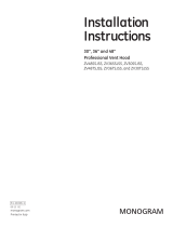
TOOLS YOU WILL NEED
SLIP JOINT PLIERS
FLAT BLADE SCREWDRIVER
PHILLIPS SCREWDRIVER
LEVEL
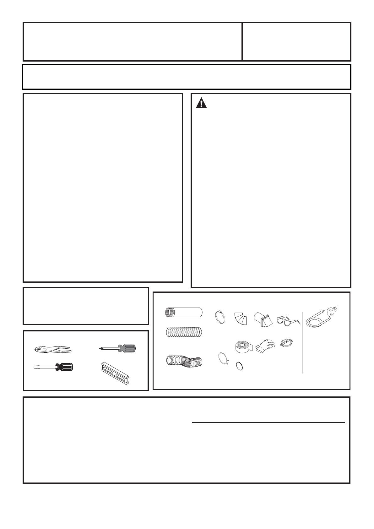
TOOLS YOU WILL NEED
GLOVES
SAFETY
GLASSES
DRYER POWER
CORD KIT
(NOT PROVIDED
WITH DRYER)
4" DUCT
CLAMPS (2)
OR
4" SPRING
CLAMPS (2)
EXHAUST
HOOD
3/4" STRAIN
RELIEF
UL RECOGNIZED
4" DIA. METAL
ELBOW
4" DIA. FLEXIBLE METAL (SEMI-RIGID)
UL LISTED TRANSITION DUCT
(IF NEEDED)
KIT WX08X10077 (INCLUDES 2 ELBOWS)
4" DIA. METAL DUCT
(RECOMMENDED)
4" DIA. FLEXIBLE METAL (FOIL TYPE)
UL LISTED TRANSITION DUCT (IF NEEDED.)
DUCT TAPE
UL RATED
120/240V,30A
WITH 3 OR 4 PRONGS.
IDENTIFY THE PLUG
TYPE AS PER THE
HOUSE RECEPTACLE
BEFORE PURCHASING
LINE CORD.
4” COVER PLATE (IF NEEDED
(KIT WE1M454)
234D2046P001 31-16719 05-13 GE
Step 1 Prepare the Area and Exhaust for Installation of
New Dryer (see section 1).
Step 2 Check and Ensure the Existing External Exhaust
is Clean (see section 1) and Meets Attached Installation
6SHFL¿FDWLRQVVHHVHFWLRQ
6WHS5HPRYHWKH)RDP6KLSSLQJ3DGVVHHVHFWLRQ
Step 4 Move the Dryer to the Desired Location.
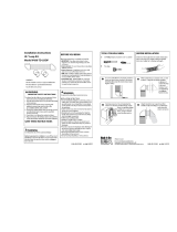
Step 5 Connect the Power Supply (see section 2).
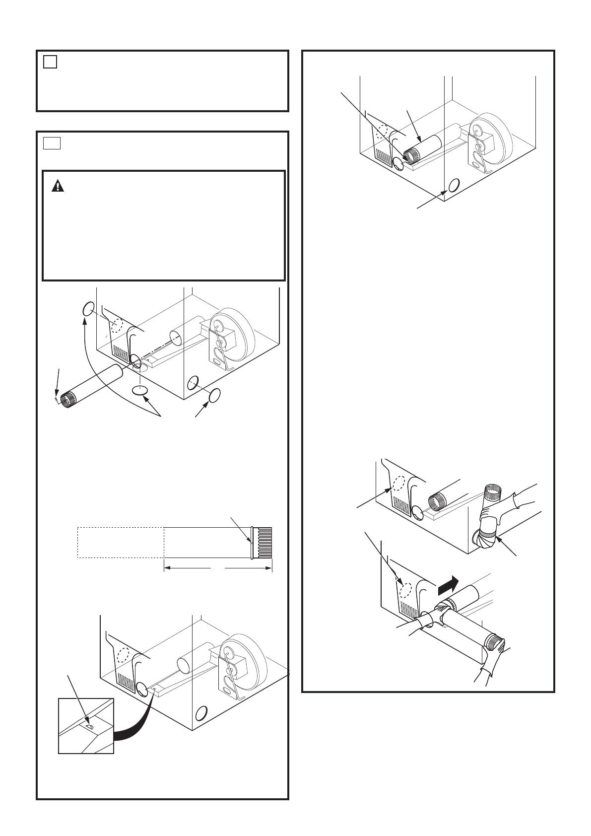
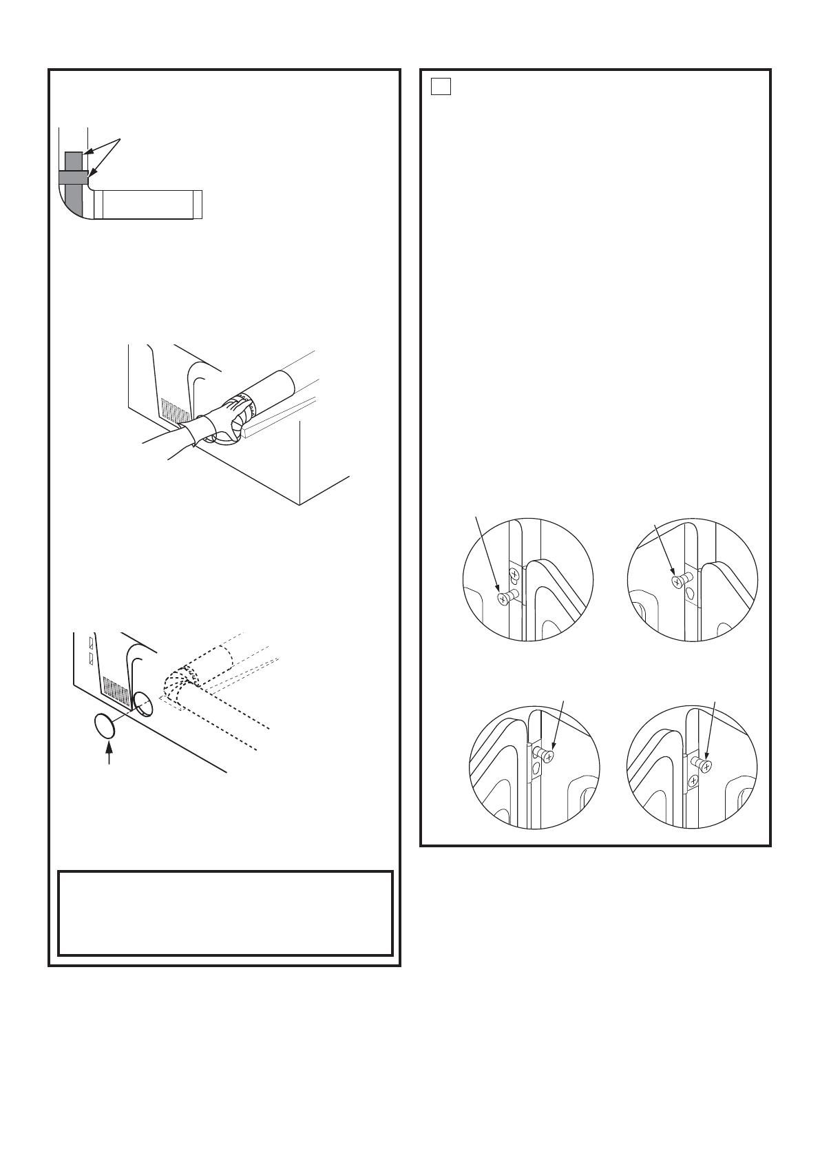
Step 6 Connect the External Exhaust (see section 4).
Step 7 Level Your Dryer (see section 5).
Step 8 Check the Operation of the Power Supply & Venting.
Step 9 Place the Owner’s Manual and the Installation
Instructions in a location where they will be noticed by the
owner.
For Alcove or Closet Installation, see section 6.
For Bathroom or Bedroom Installation, see section 7.
For Mobile or Manufactured Home see, section 8.
For garage installation (if allowed by local codes), see section 9.
For side or bottom exhaust, see section 10.
WARNING RISK OF FIRE
• To reduce the risk of severe injury or death, follow all
installation instructions.
• Clothes dryer installation must be performed by a
TXDOL¿HGLQVWDOOHU
• Install the clothes dryer according to these instructions
and in accordance with local codes.
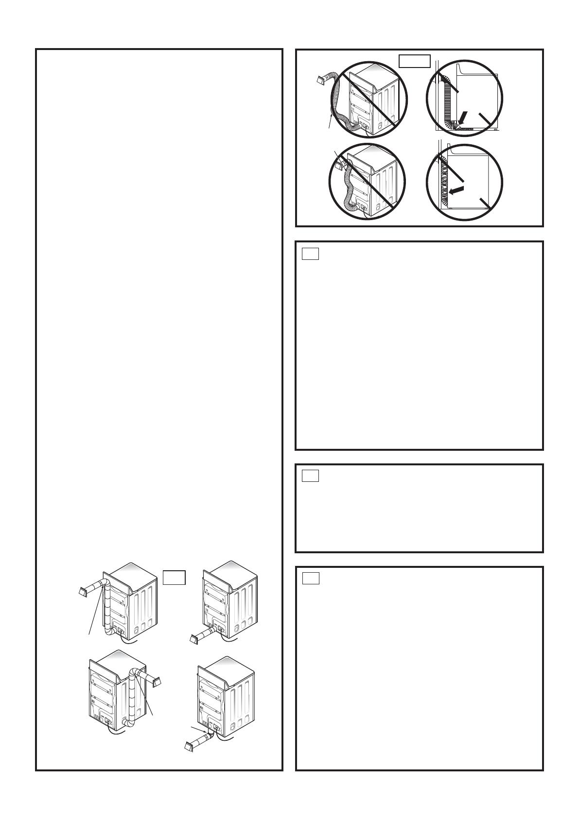
• This dryer must be exhausted to the outdoors.
• Use only 4” rigid metal ducting for exhausting the
clothes dryer to the outdoors.
• DO NOTLQVWDOODFORWKHVGU\HUZLWKÀH[LEOHSODVWLFGXFWLQJ
PDWHULDOV,IÀH[LEOHPHWDOVHPLULJLGRUIRLOW\SHGXFWLV
installed, it must be UL listed and installed in accordance
with the instructions found in Connecting The Dryer To
House Vent on page 5 of this manual. Flexible venting
materials are known to collapse, be easily crushed, and
WUDSOLQW7KHVHFRQGLWLRQVZLOOREVWUXFWGU\HUDLUÀRZDQG
LQFUHDVHWKHULVNRI¿UH
• Do not install or store this appliance in any location
where it could be exposed to water and or weather.
• Save these instructions. (Installers: Be sure to leave
these instructions with the customer).
• Install the clothes dryer according to the manufacturer’s
instructions and local codes.
Questions? Call 800.GE.CARES (800.432.2737) or visit our Web site at: GEAppliances.com
In Canada, call 1.800.561.3344 or visit www.GEAppliances.ca
Printed in Mexico