Honeywell FocusBT AP-100-BT User manual
- Category
- Bar code readers
- Type
- User manual
This manual is also suitable for

AP-010-BT and AP-100-BT
Access Point Device with Bluetooth
®
Wireless Technology
Installation Guide

Copyright
© 2008 Metrologic Instruments Inc. All rights reserved. No part of this work
may be reproduced, transmitted, or stored in any form or by any means
without prior written consent, except by reviewer, who may quote brief
passages in a review, or provided for in the Copyright Act of 1976.
Trademarks
Metrologic is a registered trademark of Metrologic
Instruments, Inc.
Products identified in this document are hereby acknowledged as
trademarks, registered or otherwise, of Metrologic Instruments, Inc. or their
respective companies.

ii
TABLE OF CONTENTS
Introduction
Product Overview ............................................................................................. 1
Base Kit Components and Optional Accessories ............................................. 1
Components ..................................................................................................... 2
Mounting Specifications.................................................................................... 3
Cable Removal................................................................................................. 3
Product Labels ................................................................................................. 4
Installation
Cable to Access Point Connection ................................................................... 5
RS232 Host Connections ................................................................................. 5
USB Host Connections..................................................................................... 6
Keyboard Wedge Host Connections ................................................................ 6
RS485 Host Connections ................................................................................. 6
Establishing Communication
Between the Scanner and the Access Point Device......................................... 7
Access Point Device Operation
Page/Disconnect Button................................................................................... 8
Visual Indicators ............................................................................................... 8
Configuration Procedures
Metro Protocol Compatibility............................................................................. 9
CodeXML Protocol Compatibility.................................................................... 10
Access Point Device Configuration in CodeXML Mode.................................. 11
Optional Configuration Bar Codes.................................................................. 12

iii
TABLE OF CONTENTS
Uploading and Downloading Settings
Uploading Settings via MetroSet2 .................................................................. 15
Downloading Settings via MetroSet2.............................................................. 16
Upgrading the Firmware..................................................................................... 17
Upgrading the Firmware in the Access Point Device...................................... 17
Upgrading FocusBT Firmware via the Access Point Device........................... 18
Design Specifications ......................................................................................... 19
Device and Cable Terminations
Device Pinout ................................................................................................. 20
Cable Pinout Connections .............................................................................. 21
Regulatory Compliance
EMC ............................................................................................................... 23
Limited Warranty ................................................................................................ 25
Index .................................................................................................................. 26
Contact Information and Office Locations........................................................... 27

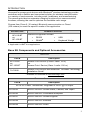
1
INTRODUCTION
Honeywell’s access point devices with Bluetooth
®
wireless technology provide
customers with a flexible and convenient solution for wireless communication
in a variety of environments, including retail, healthcare, and manufacturing.
The access point device separates charging functions from communication
functions, allowing the user to optimize the available radio range.
Choose from Class II (10 meters) Bluetooth communication or Class I
(100 meters) to meet the specific needs of the application.
ACCESS POINT INTERFACE SUPPORT
Interfaces supported include:
AP-010-BT
OR
AP-100-BT
• RS232
• RS485
S
• USB
• Keyboard Wedge
S
Applicable for IBM
®
Host applications.
Base Kit Components and Optional Accessories
BASIC KIT
Part # Description
AP-010-BT
OR
AP-100-BT
Access Point Device (Class 2 radio: 10 m)
OR
Access Point Device (Class 1 radio: 100 m)
70-79035
Access Point Device with Bluetooth
®
Wireless Technology
Installation Guide*
* Available for download at www.metrologic.com
OPTIONAL ACCESSORIES
Part # Description
AC to DC Power Transformer- Regulated 5.2VDC @ 1A output.
46-00525 90VAC-255VAC United States, Canada, and Japan
46-00526 90VAC-255VAC Continental European
46-00527 90VAC-255VAC United Kingdom
46-00528 90VAC-255VAC Australia
46-00529 90VAC-255VAC China

www.metrologic.com 2
INTRODUCTION
OPTIONAL ACCESSORIES
Part # Description
55-55500-3 RS232 Straight PowerLink Cable, Black
55-55502-N-3 Keyboard Wedge Straight Cable, Black
55-55512-3 RS485
S
Applications,Straight PowerLink Cable
55-55535-N-3 USB Type A Straight Cable, Black
55-55567-3 AUX Cable, Black
S
Applicable for IBM
®
host applications.
Other items may be ordered for the specific protocol being used. To order additional items,
contact the dealer, distributor or call Metrologic’s Customer Service Department at
1-800-ID-METRO or 1-800-436-3876.
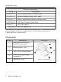
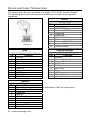
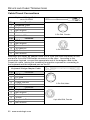
Components
ITEM NO. DESCRIPTION LOCATION
1
Page/Disconnect Button &
Blue LED (see page 8)
2 Mounting Holes, Qty. 2
3 10-Pin RJ45, Female Socket
4
Pinhole for Cable Release
(see page 5)
5 Address Bar Code
Figure 1. Components
3
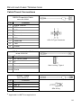
INTRODUCTION
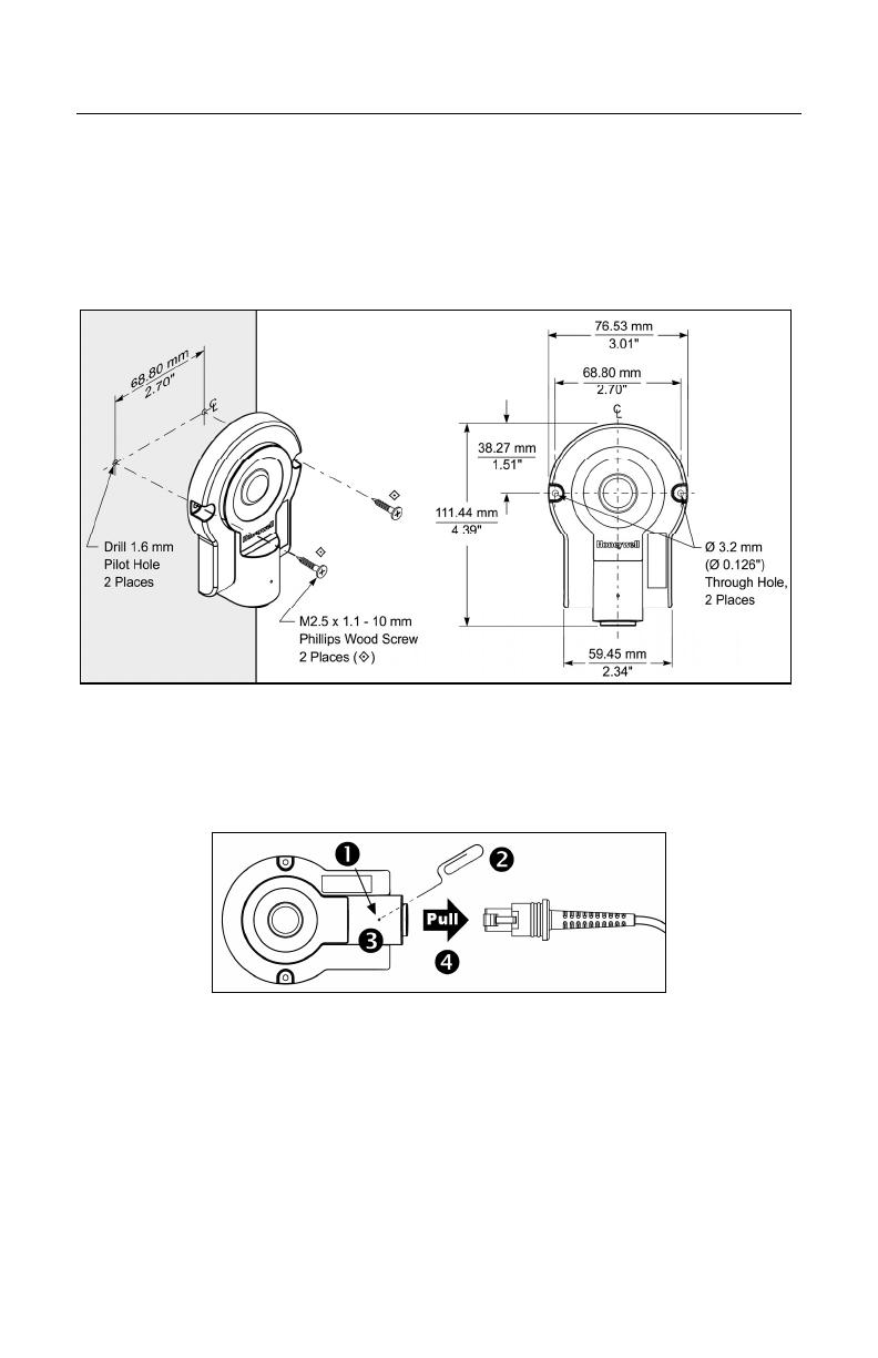
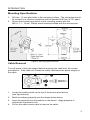
Mounting Specifications
1. Drill two, 1.6 mm pilot holes in the mounting surface. The pilot holes should
be located on a common centerline and be spaced 68.80 mm (2.70") apart.
2. Secure the access point device to the mounting surface with the
M2.5 x 1.1 - 10 mm, Phillips wood screws provided with the access point.
Figure 2. Mounting Specifications
Cable Removal
Turn off power to the host system before removing the cable from the access
point device. If the cable is a PowerLink cable, disconnect the power supply on
the cable.
Figure 3. Cable Removal
1. Locate the small pinhole on the top of the access point device
(see figure above).
2. Bend an ordinary paperclip into the shape shown above.
3. Insert the paperclip into the pinhole on the device. Apply pressure to
release the connector’s lock.
4. Pull on the cable’s strain-relief to remove the cable.
www.metrologic.com 4
INTRODUCTION
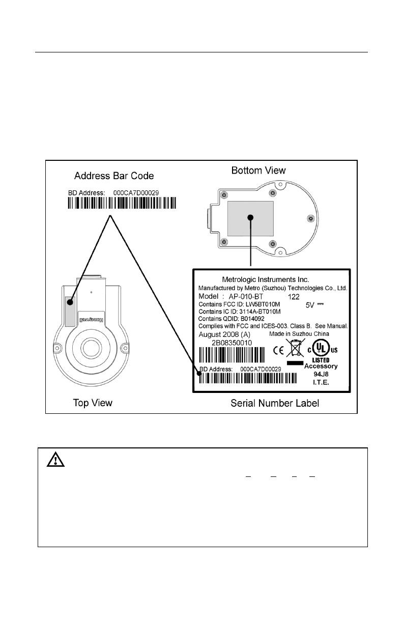
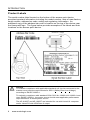
Product Labels
The serial number label located on the bottom of the access point device
provides important information including the model number, date of manufacture,
serial number, address bar code, safety and regulatory information. An
additional copy of the address bar code is location on the top of the device near
the Honeywell logo. The figure below provides examples of the labels and their
locations on the access point device.
Figure 4. Label Location with Examples
Caution
To maintain compliance with applicable standards, all circuits connected to the
scanner must meet the requirements for SELV (Safety Extra Low Voltage)
according to EN/IEC 60950-1.
To maintain compliance with standard CSA C22.2 No. 60950-1/UL 60950-1 and
norm EN/IEC 60950-1, the power source should meet applicable performance
requirements for a limited power source.
The AP-010-BT and AP-100-BT are intended for use with Listed UL computer
and/or Listed PS with LPS/Class 2 output.
5
INSTALLATION
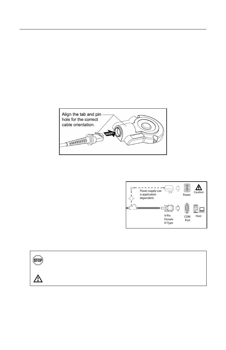
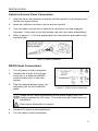
Cable to Access Point Connection
1. Align the tab on the modular connector with the pinhole on the access point
device (see figure below).
2. Insert the modular connector into the device’s socket.
3. Test the cable’s connection to ensure the connector lock has engaged.
Important: If the cable is not fully latched, the unit can power intermittently.
4. Refer to pages 5 – 6 for the appropriate host connections applicable to the
interface type.
Figure 5. Cable Installation
RS232 Host Connections
1. Turn off power to the host system.
2. Connect the female, 9-Pin D-type
connector to a dedicated RS232
communication port on the host
system.
3. Plug the external power supply into
the power jack on the PowerLink
cable.
Check the AC input requirements of the power supply verify the
voltage matches the AC outlet. The outlet must be located near the
equipment.
See caution information on page 4.
4. Connect AC power to the transformer.
5. Turn on power to the host system.
Figure 6. RS232 Host Connections

www.metrologic.com 6
INSTALLATION
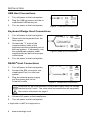
USB Host Connections
1. Turn off power to the host system.
2. Plug the USB connector into the to
a dedicated USB serial port.
3. Turn on power to the host system.
Keyboard Wedge Host Connections
1. Turn off power to the host system.
2. Disconnect the keyboard from the
host system.
3. Connect the “Y” ends of the
communication cable to the
keyboard and the keyboard port on
the host system. If necessary, use
the male/female adapter cable
supplied with the device for proper
connections.
4. Turn on power to the host system.
RS485
S
Host Connections
1. Turn off power to the host system.
2. Connect the SDL connector into
a dedicated Port 9 on the host
system.
3. Plug the external power supply
into the power jack on the
PowerLink cable
Check the AC input requirements of the power supply verify the voltage
matches the AC outlet. The outlet must be located near the equipment.
See caution information on page 4.
4. Connect AC power to the transformer.
5. Turn on power to the host system.
S
Applicable for IBM
®
Host applications.
Figure 8. KBW Host Connections
Figure 7. USB Host Connections
Figure 9. RS485 Host Connections

7
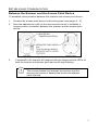
ESTABLISHING COMMUNICATION
Between the Scanner and the Access Point Device
To establish communication between the scanner and access point device:
1. Connect the access point device to the host system (see pages 5 - 6).
2. Scan the address bar code on the access point device to establish a
communication connection between the scanner and the access point
device.
Figure 10. Address Bar Code
3. If successful, the scanner will respond with two beeps and the LED's on
both the scanner and access point device will stop flashing.
Important Note:
The communication link between the scanner and the
access point device is determined by the last address
code scanned.
www.metrologic.com 8
ACCESS POINT DEVICE OPERATION
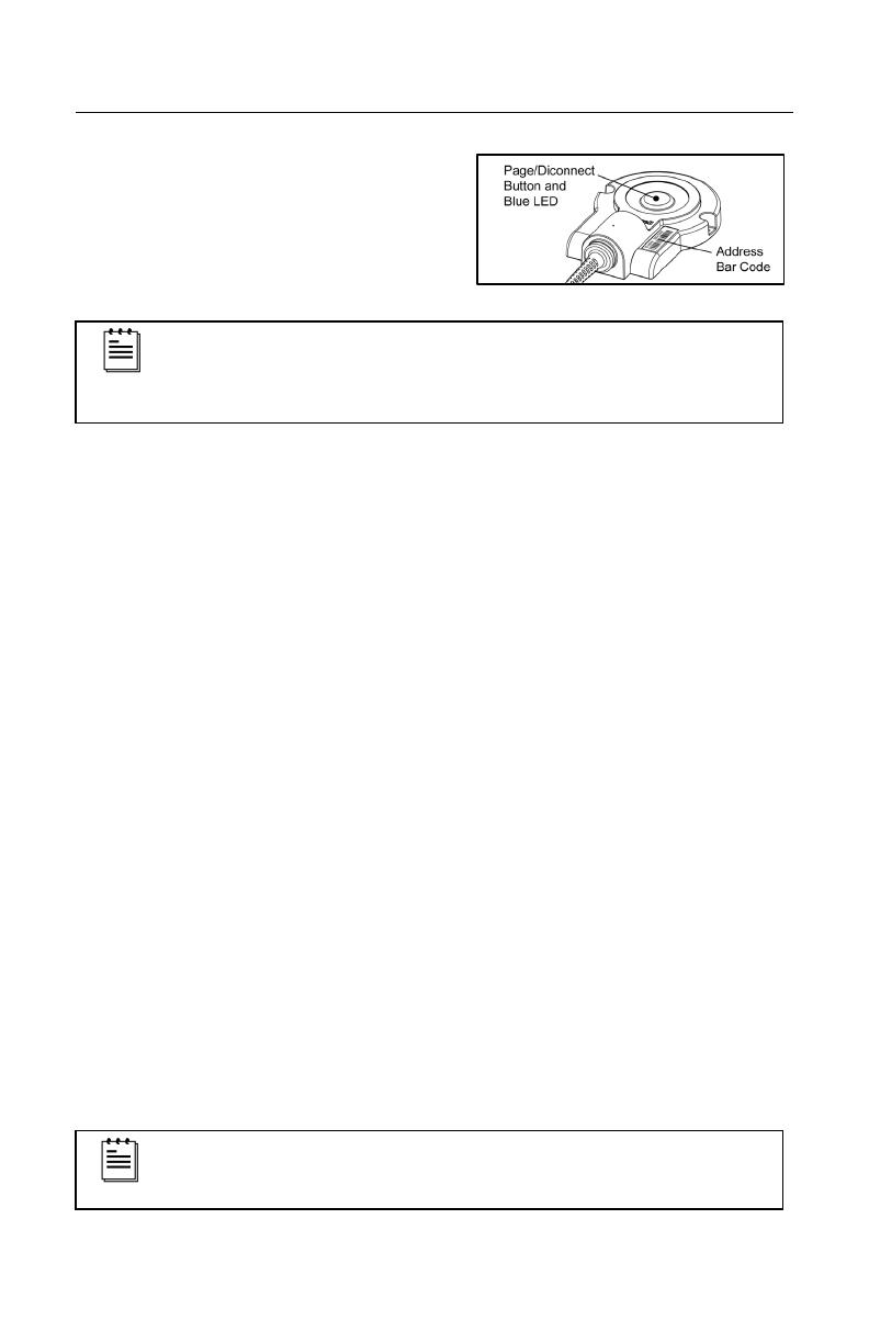
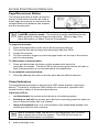
Page/Disconnect Button
The access point has a button located on
the top of the device that can be used to
either page the scanner or disconnect the
communication link between the scanner
and the access point.
Figure 11.
The page and disconnect button features are not supported in
CodeXML protocol mode. The scanner must be configured for the
Metro protocol mode for feature functionality. Refer to page 9 for
more information on Metro Protocol Compatibility.
To page the scanner:
1. Press the page button on the top of the access point device.
2. The scanner will start to beep and alternately flash the LEDs.
3. Locate the scanner.
4. Pull the scanner’s trigger or press the page button on the top of the access
point to stop paging.
To disconnect communication:
1. Press and hold down the button on the access point device for
more than 3 seconds. The blue LED on the access point device will start to
flash indicating there is no communication link established.
To re-establish communication:
1. Scan the address bar code on access point device with the scanner.
Visual Indicators
The page/disconnect button is also the blue LED status indicator (see figure
above). The activity of the blue LED reflects the connection, operation and
communication status of the access point device.
If the blue LED is:
• not illuminated, the access point device is not receiving power.
• flashing on and off, the access point device is receiving power but does not
have a communication link to a scanner.
• always illuminated there is a communication link established between the
access point device and a scanner.
After a successful scan, the Blue LED will temporarily turn off while
data is being sent to the host system. The LED will turn back on
when data transmission is complete.
9
CONFIGURATION PROCEDURES
The following information is for replacement applications or situations requiring
scanner reconfiguration. Some of the configuration procedures require the user
to scan the recall defaults bar code. If the recall defaults code is scanned, the
scanner’s factory pre-configurations and custom configurations will be lost.
The scanner will need to be reconfigured in order to work with the access point
device.
Metro Protocol Compatibility
By default, the Metro protocol is enabled before the access point device and
scanner leave the factory. The protocol supports page/disconnect functions,
scanner firmware upgrades through the access point device, and all features
supported by the Code XML protocol.
When a scanner is using the Metro protocol, configuration data is stored in the
access point device. The stored data is automatically sent to the scanner when a
communication link is established between the scanner and the access point
device. Scanned data and custom configuration settings will be lost if a
communication link is not established between the scanner and the access
point.
Scanner configuration changes can be done either by scanning configuration bar
codes in the MetroSelect
Single-Line Configuration Guide (MLPN 00-02544
x
), or
with the MetroSet2
®
program, version 3.2.0.16 or higher.
Metro Protocol Firmware Requirements
Scanner Model and REV Firmware Version
FocusBT (A) 40268 or higher
FocusBT (B) 40268 or higher
Focus BT (F) all versions are compatible
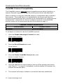
To configure a scanner to use the Metro protocol:
1. Scan the Recall Defaults bar code then the Enable Metro Protocol bar
code.
Recall Defaults
³999998
Enable Metro Protocol
³125614
2. Scan the address bar code located on the top of the access point device
(see Figure 11, on page 8) to establish a communication link between the
scanner and access point.
3. The scanner will beep and the access point’s blue LED will flash once.
4. The scanner will receive the configuration from the access point device
automatically.

www.metrologic.com 10
CONFIGURATION PROCEDURES
CodeXML Protocol Compatibility
The CodeXML protocol does not support page/disconnect button functions, or
scanner firmware upgrades through the access point device and Metroset2.
When a scanner is using the CodeXML protocol, configuration data is stored in
the scanner. The stored data is not transmitted to the access point device.
Special configuration steps are required for the customization of system formats
and protocols. Instructions on how to configure a scanner in the CodeXML
protocol mode via the access point device are outlined on page 11.
CodeXML Firmware Requirements
Scanner Model Firmware Version
Focus BT 15701 or higher
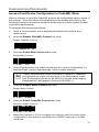
To configure a scanner to use the CodeXML protocol:
1. Scan the Disable Metrologic Protocol bar code.
Disable Metro Protocol
³125604
2. Scan the Recall Defaults bar code.
Recall Defaults
³999998
3. Scan the Enable CodeXML Protocol bar code.
Enable CodeXML Protocol
³125617
4. Scan the address bar code located on the top of the access point device
(see Figure 11, on page 8) to establish a communication link between the
scanner and access point.
5. The scanner will beep to indicate a connection has been established.

11
CONFIGURATION PROCEDURES
Access Point Device Configuration in CodeXML Mode
When a scanner is using the CodeXML protocol all configuration data is stored in
the scanner. Since the data is not transmitted to the access point device, the
following process is required to configure the device for custom system formats
or protocol requirements.
To configure the access point device:
1. Verify a communication link is established between the scanner and
access point.
2. Scan the Disable CodeXML Protocol bar code.
Disable CodeXML Protocol
³125607
3. Scan the Enable Metro Protocol bar code.
Enable Metro Protocol
³125614
4. Scan all configuration bar codes required for the custom configuration (i.e.
keyboard type, country keyboard type, suffix or prefix settings).
Country keyboard bar codes are located on page 14. Additional
configuration bar codes can be found in the MetroSelect Single-
Line Configuration Guide (PN 00-02544
x
) and the Area Imaging
Supplemental Configuration Guide (PN 00-02281
x
).
5. Scan the Disable Metro Protocol bar code.
Disable Metro Protocol
³125604
6. Scan the Enable CodeXML Protocol bar code.
Enable CodeXML Protocol
³125617
† MetroSet2 (version 3.2.0.16 or higher) can also be used for access point
configuration if the device is connected to an RS232 com port or a USB
serial port.

www.metrologic.com 12
CONFIGURATION PROCEDURES
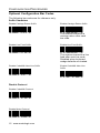
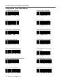
Optional Configuration Bar Codes
The following bar codes are for reference only.
Suffix Characters
Disable Carriage Return Suffix
³116603
Enable Carriage Return Suffix
³116613
The scanner transmits a
carriage return after each
bar code.
Disable Line Feed Suffix
³116602
Enable Line Feed Suffix
³116612
The scanner transmits a line
feed after each bar code.
Disabled when keyboard
wedge defaults are loaded.
Disable CodeXML New Line Suffix
³125606
Enable CodeXML New Line
Suffix
³125616
Disable Protocol
Disable CodeXML Protocol
³125607
Disable Metro Protocol
³125604

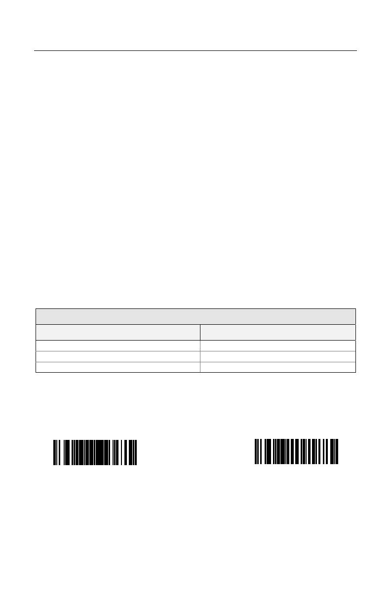
13
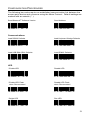
CONFIGURATION PROCEDURES
The following bar codes require an established communication link between the
access point device and a scanner using the Metro Protocol. Default settings are
marked with an asterisk ( * ).
Send Bluetooth
®
Software Version
³998044
Send Address
³998045
Communications
Load RS232 Defaults
³999992
Load Keyboard Wedge Defaults
³999994
Load USB IBM OEM Defaults
³999970
Load RS485 Defaults
³999952
LED
* Enable LED
³118310
Disable LED
³118300
* Enable LED Flash
when Disconnected
³123712
Disable LED Flash
when Disconnected
³123702
* Bright LED
³123906
Dim LED
³123916

www.metrologic.com 14
CONFIGURATION PROCEDURES
Country/Scan Code Table Selects
* Enable USA Keyboard
³416260
Enable Swiss Keyboard
³416280
Enable Spanish Keyboard
³416250
Enable Italian Keyboard
³416240
Enable German Keyboard
³416230
Enable French Keyboard
³416220
Enable UK Keyboard
³416210
Enable Belgium Keyboard
³416200
Enable Japanese Keyboard
³4162100
Enable IBM 4700 Financial
Keyboard
³416270
Enable Sweden/Finland Keyboard
³416290
Enable Russian Keyboard
³4162130
Enable Turkish Keyboard
³4162120
Enable Slovenian Keyboard
³4162110
15
UPLOADING AND DOWNLOADING SETTINGS
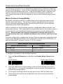
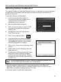
Uploading Settings via MetroSet2
The upload
†
feature in MetroSet2 allows the user to retrieve the current software
number and configuration settings of an access point device connected to a
personal computer.
To upload settings via MetroSet2:
1. Verify the access point device is
connected to the host system and a
communication link has been
established with a scanner.
2. Start the MetroSet2 software.
3. Click on the plus sign (+) next to POS
Scanners to expand the supported
scanner list.
4. Choose the Focus BT with Access
Point
‡
from the list.
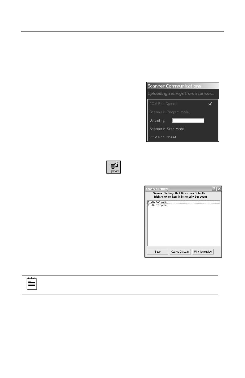
5. Click on the Upload button.
6. A communications window will open
displaying the progress of the upload.
A message will appear in the window
when the upgrade is complete.
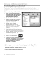
7. Click on the Tools menu at the top of the
screen.
8. Select View Current Settings from the
drop down list.
9. The Scanner Settings window will open
listing the custom settings uploaded
from the access point device. Default
settings will not be listed (see example
in
Figure 13).
All the settings shown in
Figure 13 are for illustrative purposes only
and will differ depending upon the configuration.
†
Minimum system requirements: A personal computer with Microsoft
®
Windows
®
95 or greater with an available RS232 serial or USB port and
MetroSet2 (minimum software version 3.2.016).
‡ Scanner model is application dependent.
Figure 12. Scanner Communications
Figure 1
3
. Scanner Settings
www.metrologic.com 16
UPLOADING AND DOWNLOADING SETTINGS
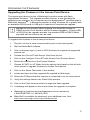
Downloading Settings via MetroSet2
The download
†
feature in MetroSet2 allows the user to download custom
configuration settings selected in MetroSet2 to the access point and the linked
scanner
‡
.
To download settings via MetroSet2:
1. Verify the access point device is
connected to the host system and
a communication link has been
established with a scanner.
2. Start the MetroSet2
†
software.
3. Click on the plus sign (+) next to
POS Scanners to expand the
supported scanner list.
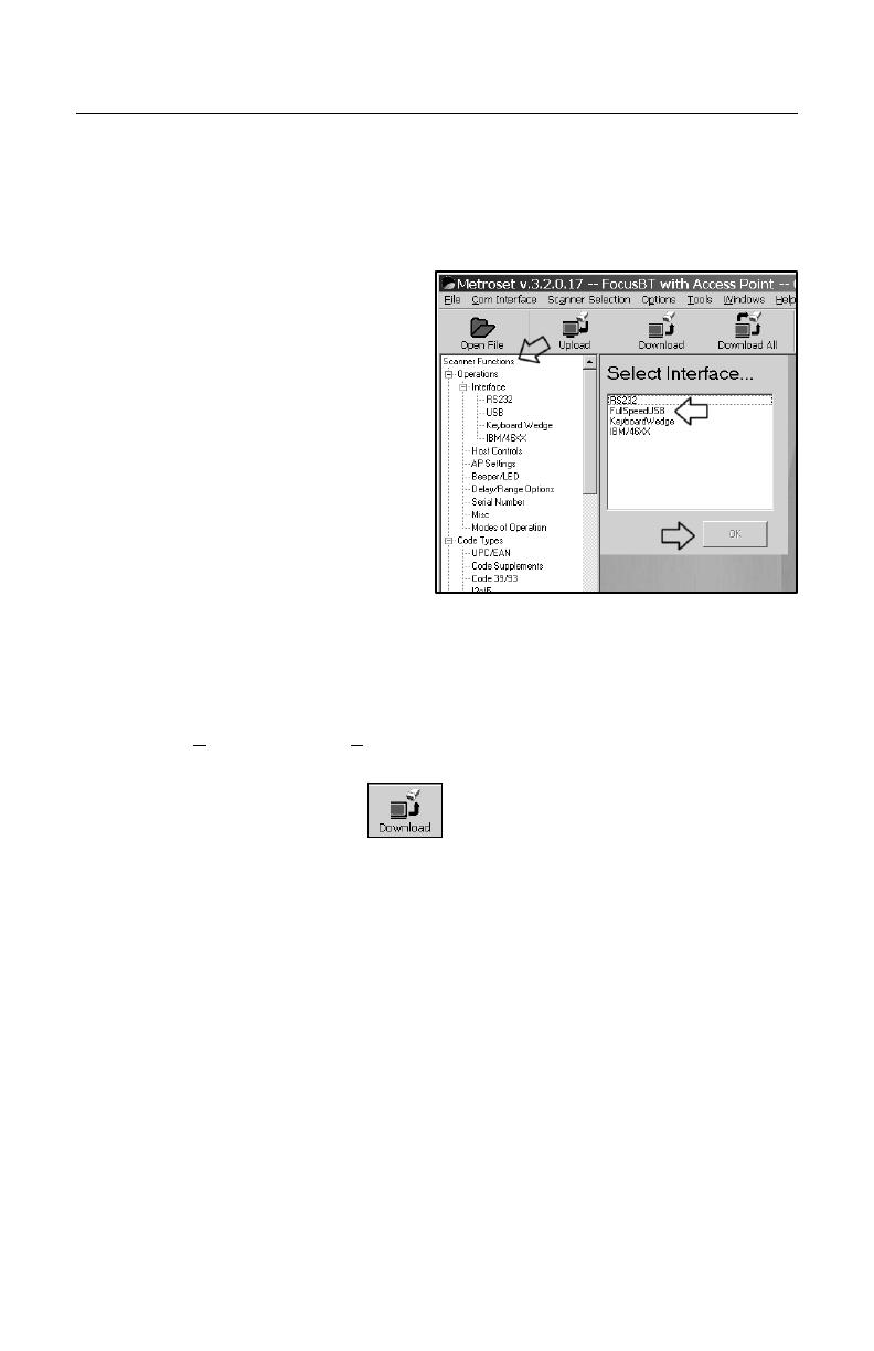
4. Choose Focus BT with
Access Point
‡
from the list.
5. Select an interface (i.e. RS232,
Keyboard Wedge, USB) then
click OK.
6. Select and modify the configuration
options in the Scanner Functions Menu.
7. Choose Save As from the File menu to
save the configuration.
8. Click on the Down button.
9. A communications window will open
displaying the progress of the download.
The unit will beep and a message will
appear in the window when the
download is complete.
† Minimum system requirements: A personal computer with Microsoft®
Windows® 95 or greater with an available RS232 serial or USB port and
MetroSet2 (minimum software version 3.2.016).
‡ Scanner model is application dependent.
Figure 14. Global Defaults Page
Page is loading ...
Page is loading ...
Page is loading ...
Page is loading ...
Page is loading ...
Page is loading ...
Page is loading ...
Page is loading ...
Page is loading ...
Page is loading ...
Page is loading ...
Page is loading ...
-
 1
1
-
 2
2
-
 3
3
-
 4
4
-
 5
5
-
 6
6
-
 7
7
-
 8
8
-
 9
9
-
 10
10
-
 11
11
-
 12
12
-
 13
13
-
 14
14
-
 15
15
-
 16
16
-
 17
17
-
 18
18
-
 19
19
-
 20
20
-
 21
21
-
 22
22
-
 23
23
-
 24
24
-
 25
25
-
 26
26
-
 27
27
-
 28
28
-
 29
29
-
 30
30
-
 31
31
-
 32
32


Honeywell FocusBT AP-100-BT User manual
- Category
- Bar code readers
- Type
- User manual
- This manual is also suitable for
Ask a question and I''ll find the answer in the document
Finding information in a document is now easier with AI
Related papers
-
Honeywell MS7120 User manual
-
Honeywell MS5145 Eclipse User guide
-
Honeywell 53-53235X-N-3 User guide
-
Metrologic VoyagerGS 9590 User manual
-
Honeywell MS9540 Voyager User manual
-
Metrologic Instruments MS1633 User manual
-
-
Metrologic 5S-5S235-3 User manual
-
-
Metrologic MS9500 User manual
Other documents
-
HandStands XV-G2 User guide
-
Metrologic Instruments MS9590i User manual
-
-
BTC 9116 User manual
-
-
-
-
-
-