
AMPLIFIERS
INSTALLATION GUIDE
SI
-
SI
-
SI
-

2
WWW.NILESAUDIO.COM
Thank you for purchasing a Niles Systems Integration Amplier
®
, one of the most
exible and convenient ampliers ever offered. Like all Niles products, your new
amplier is built to the highest standards of quality control and reliability. With
proper installation and operation, you’ll enjoy years of trouble-free use.
TABLE OF CONTENTS
Introduction 4
Features and benefits 5
Installation Considerations 7
Front and rear panel details 11
Installation 13
Operation 17
Troubleshooting guide 18
Specifications 20
CONGRATULATIONS!

3
NILES AUDIO CORPORATION – 1-800-BUY-HIFI – 1-760-710-0992
2 Channel, BridgaBle Power amPlifiers
ImpORTANT SAFETy INSTRUCTIONS
1. Read these instructions.
2. Keep these instructions.
3. Heed all warnings.
4. Follow all instructions.
5. Do not use this apparatus near water.
6. Clean only with a dry cloth.
7. Do not block any ventilation openings. Install in
accordance with the manufacturer’s instructions.
8. Do not install near any heat sources such as
radiators, heat registers, stoves or other apparatus
(including ampliers) that produce heat.
9. Do not defeat the safety purpose of the polarized
or grounding-type plug. A polarized plug has two
blades with one wider than the other. A grounding-
type plug has two blades and a third grounding
prong. The wide blade or the third prong is provided
for your safety. If the provided plug does not t into
your outlet, consult an electrician for replacement of
the obsolete outlet.
10. Protect the power cord from being walked on
or pinched, particularly at plugs, convenience
receptacles and the point where they exit from the
apparatus.
11. Only use attachments/accessories specied by
the manufacturer.
12. Use only with the cart, stand,
tripod, bracket or table specied
by the manufacturer or sold with
the apparatus. When a cart is
used, use caution when moving
the cart/apparatus combination to
avoid injury from tip-over.
13. Unplug this apparatus during lightning storms or
when unused for long periods of time.
14. Refer all servicing to qualied service personnel.
Servicing is required when the apparatus has been
damaged in any way, such as power supply cord or
plug is damaged, liquid has been spilled or objects
have fallen into the apparatus, the apparatus has
been exposed to rain or moisture, does not operate
normally, or has been dropped.
15. Do not expose this apparatus to dripping or
splashing and ensure that no objects lled with
liquids, such as vases, are placed on the apparatus.
16. To completely disconnect this apparatus from
the AC Mains, disconnect the power supply cord
plug from the AC receptacle.
17. The power supply cord (sometimes referred
to as the “Mains Plug”) is used as the disconnect
device and shall remain accessible and operable at
all times.
18. Do not expose batteries to excessive heat such
as sunshine, re or the like.
19. Open ame sources, such as lighted candles,
should NOT be placed on the apparatus.
WARNING: To reduce the risk of fire or electric
shock, do not expose this apparatus to rain or
moisture.
The lightning ash with arrowhead
symbol, within an equilateral triangle, is
intended to alert the user to the
presence of uninsulated “dangerous
voltage” within the product’s enclosure
that may be of sufcient magnitude to constitute a
risk of electric shock to persons.
The exclamation point within an
equilateral triangle is intended to alert
the user to the presence of important
operating and maintenance (servicing)
instructions in the literature accompanying the
product.
FCC Required Text:
NOTE: This equipment has been tested and found
to comply with the limits for a Class B digital
device, pursuant to part 15 of the FCC Rules.
These limits are designed to provide reasonable
protection against harmful interference in a
residential installation. This equipment generates,
uses, and can radiate, radio frequency energy
and, if not installed and used in accordance with
the instructions, may cause harmful interference
to radio communications. However, there is no
guarantee that interference will not occur in a
particular installation. If this equipment does cause
harmful interference to radio or television reception,
which can be determined by turning the equipment
off and on, the user is encouraged to try to correct
the interference by one or more of the following
measures:
—Reorient or relocate the receiving antenna.
—Increase the separation between the equipment
and receiver.
—Connect the equipment into an outlet on a
circuit different from that to which the receiver is
connected.
—Consult the dealer or an experienced radio/TV
technician for help.
Changes or modications not expressly approved
by the party responsible for compliance could void
the user’s authority to operate the equipment.

4
WWW.NILESAUDIO.COM
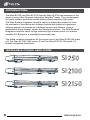
INTROdUCTION
BRIdGABLE pOwER AmpLIFIERS
SI
-
SI
-
SI
-
The Niles SI-250, the Niles SI-2100 and the Niles SI-2150 are members of the
award-winning Niles Systems Integration Amplier
®
family. They are designed
for home theaters and whole house audio systems requiring high power.
The Niles System Integration Amplier family is specically created to solve
the problems of interfacing with different brands and models of equipment,
different acoustic environments in different rooms, and different kinds of
applications: home theater, stereo, and background music. The Niles Systems
Integration Amplier family brings extremely high current power to a custom
installed A/V System in a remarkably convenient way.
This guide contains information for the proper use of the Niles SI-250 (50 watts
x 2), the Niles SI-2100 (100 watts x 2) and the Niles SI-2150 (150 watts x 2)
System Integration Ampliers
®
.

5
NILES AUDIO CORPORATION – 1-800-BUY-HIFI – 1-760-710-0992
2 Channel, BridgaBle Power amPlifiers
FEATURES ANd BENEFITS
REAL wORLd pOwER
The SI-250, the SI-2100 and the SI-2150 deliver 50 watts, 100 watts, and 150
watts per channel at 8 ohms and 100 watts, 220 watts, 270 watts per channel at
4 ohms respectively. You’ll get tremendous bass and dynamics from every pair
of speakers connected.
TRANSpARENT SOUNd
The audio circuitry of the Niles System Integration Ampliers
®
is constructed
using the nest parts available; including 1% metal lm resistors, high quality
capacitors, and oversized heat sinks. All this attention to technical detail creates
a sound that is clear and uncolored with phenomenal imaging.
FREEdOm FROm CROSSTALk
Each channel of the Niles System Integration Amplier is powered via its
own independent power supply. This increases the isolation between the two
channels and eliminates cross talk, guaranteeing you absolute silence as the
backdrop to your music.
CURRENT FOR REACTIvE LOAdS
The high current design of the Niles System Integration Ampliers assures that
even unusual and reactive loads are handled with ease. A massive toroidal
transformer (SI-250) and cutting edge digital power supplies (SI-2100, SI-2150)
provide more than ample current to your system.
FREEdOm FROm FAN NOISE
The oversized heat sinks inside the System Integration Ampliers allow the
amplier circuitry to stay cool even when operating into low impedance loads
without the distracting noise created when using fan-cooled ampliers.
INdEpENdENT LEvEL CONTROLS
Each amplier channel features an independent level control enabling precise
volume matching to the rest of the system. These level controls can also limit
volume to prevent abuse of the system.

6
WWW.NILESAUDIO.COM
FEATURES ANd BENEFITS
LIFETImE CONNECTIONS
The Niles System Integration Amplier
®
family features gold plated stereo
inputs, cascade stereo outputs, and ve way binding posts to ensure perfect
connections without corrosion for years to come.
TURN-ON mOdES
The Niles System Integration Amplier
®
family features three turn-on modes:
1. Music Sense, 2. External Voltage Trigger, 3. Manual Turn-On via the front
panel switch. You can congure a Niles Systems Integration Amplier
®
to
interface with any kind of system and have the unit automatically turn on.
AUTOmATIC pROTECTION
The Niles System Integration Amplier
®
family is equipped with sophisticated
protection circuits. In the unlikely event that a problem occurs, the amplier
shuts itself off. When conditions return to normal, regular operation resumes.
STATUS dISpLAy FOR TROUBLEShOOTING
LED indicators on the front panel indicate: Power, Active Status, and a
Protection Warning. With a glance at the front panel, a troubleshooter is quickly
provided with key information!
CONTROL OUTpUT
A 12 Volt DC output is provided whenever the amplier is on, allowing you to
operate voltage triggered devices like motorized screens and curtains.
BRIdGEd mOdE
The Niles System Integration Amplier
®
family can be operated in a bridged mono
conguration. In this conguration, the SI-250, the SI-2100 and the SI-2150
deliver 225 watts, 400 watts, and 550 watts respectively. Bridged mode is perfect
for subwoofer, rock speakers or any applications requiring high power output.
COmpACT 1U dESIGN
The SI-250, the SI-2100 and the SI-2150 all share the same compact low prole
design requiring only a single rack space (1U).
dESIGNEd ANd ENGINEEREd IN ThE USA
Limited two-year parts and labor warranty.

7
NILES AUDIO CORPORATION – 1-800-BUY-HIFI – 1-760-710-0992
2 Channel, BridgaBle Power amPlifiers
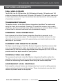
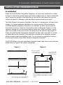
INSTALLATION CONSIdERATIONS
pLACEmENT
Place the Niles System Integration Amplier
®
on a at level surface like a table
or shelf. It should be placed upright so that its weight rests on the four attached
feet. Placing the weight of the amplier on the rear or front panel for even an
instant will result in damage to the amplier’s connectors and controls.
The Niles System Integration Amplier
®
, like any hi- component, will last much
longer if it is given adequate ventilation for proper cooling. When installing
the Niles System Integration Amplier
®
in a cabinet, be sure that the rear of
the cabinet is open to fresh air to provide proper cooling (see Figure 1). If the
cabinet’s design will not accommodate an open rear, install two small “boxer
fans” to provide continuous air ow into and out of the cabinet (see Figure 2).
Place the Niles System Integration Amplier
®
so that there is at least 7” of free
air space above the chassis. If the amplier is located on a carpeted surface,
place a board under the amplier’s feet. Do not block the ventilation holes on
the top and bottom of the Niles System Integration Amplier
®
.
CAUTION! When using low impedance speaker loads (less than 8 ohms Normal
Mode) refer to Figure 2 for proper placement.
Allow a minimum of 2” of depth behind unit
to accommodate cables and connectors.
If the cabinet rear is not open to fresh air or if you’re
using low impedance loads, install two “boxer fans”
to provide continuous air ow into and out of the
cabinet.
Boxer Fan (55 CFM)
directly centered 2”
behind the Amplier.
Boxer Fan (55 CFM)
directly centered 7”
on top of the Amplifer.
Figure 1
Figure 2
Make sure that there is a minimum of 7” of free air
space above the amplier for proper ventilation.

8
WWW.NILESAUDIO.COM
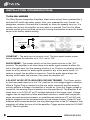
INSTALLATION CONSIdERATIONS
TURN-ON mOdES
The Niles System Integration Amplier
®
draws more current than a preamplier’s
switched AC outlet can safely supply. Also, your preamplier may “thump” at
dangerous volumes if the amplier is already on when the preamp turns on. It is
usually best to turn the amplier on only when it is needed. The Turn-On Mode
selector switch gives you three options for turning the amplier on and off. Audio
sense is the factory default setting.
CONSTANT - The auto turn-on circuitry is off. The front panel master power
switch operates the amplier. In is “On”, out is “Off”.
AUDIO SENSE - The master switch on the front panel must be in the “On”
position. The amplier is off when there is no audio signal present at either the
left or the right input, but the sensing circuitry is on. The turn-on sensing circuitry
looks for a tiny amount of audio signal present at any of the audio inputs. If it
detects a signal, the amplier is turned on. Once the audio signal stops, the
sensing circuit waits two minutes, then turns the amplier off.
3-24 VOLT AC/DC OPTO-ISOLATED VOLTAGE TRIGGER - The Power switch
on the front panel must be in the “On” position for the voltage trigger to function.
When a Trigger Plug is inserted into the rear panel connector and the sensing
circuitry detects a voltage, the amplier is turned on. Once the Trigger voltage is
turned off, the sensing circuit instantly turns the amplier off. The amplier is off
when there is no 3-24V AC or DC voltage detected at the trigger input. Voltage
triggers can be supplied by Niles automated switchers, some video projectors,
some surround sound processors, or something as simple as a 12 volt AC wall
adapter plugged into the switched outlet of your stereo receiver. Linear DC wall
adapters are not recommended; the long discharge time of the DC adapter’s lter
capacitor will delay the turn-off of the amplier. Trigger sources must be 3-24VAC
or DC, 20mA or greater.
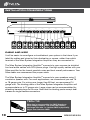
INSTALLATION CONSIdERATIONS
100-120V / 220-240V~
50 / 60Hz 600W
Systems
Integration
Amplif ier
®
TURN ON MODE
AUDIO SENSE
CONSTANT
3-30V
AC/DC
TRIGGER
INPUT
12V
CONTROL
OUT
L R
L
R
BUS
OUTPUT
FOR
BRIDGED
MODE
L
R
LEVELS
MAIN BUS
INPUT
STEREO
BRIDGED
CLASS 2 WIRING
LEFT RIGHT
This device complies with Part 15 of the FCC Rules.
Operation is subject to the following two conditions:
(1) this device may not cause harmful interference, and
(2) this device must accept any interference received,
including interference that may cause undesired
operation.
Niles Audio, Carlsbad, California, USA
Designed and Engineered in the U.S.A. Made in China
T5AL, 250V
Serial No.
CAUTION: replace only with same type and rating of fuse.
ATTENTION: remplacer uniquement avec le même type
et calibre du fusible.
Minimum impedance:
2.66 Ω (stereo mode)
4 Ω (bridged mode)

9
NILES AUDIO CORPORATION – 1-800-BUY-HIFI – 1-760-710-0992
2 Channel, BridgaBle Power amPlifiers
INSTALLATION CONSIdERATIONS
BRIdGEd mOdE
The Niles System Integration Amplier
®
bridged mode switch allows you to create
a more powerful amplier by combining both channels into one (8 ohm minimum).
Stereo mode is the factory default setting.
In the bridged mode, connect the speakers to the left red positive terminal and
the right red positive terminal. In the bridged mode the right channel’s red terminal
becomes positive and the left channel’s red terminal becomes negative.
DO NOT USE THE BLACK NEGATIVE (-) TERMINALS. THE SIGNAL IS AT THE RED
POSITIVE (+) TERMINALS ONLY.
The line level input signal must connect to the left channel input of the amplier
when using bridged mode.
mULTIpLE SpEAkER LOAdS
The Niles System Integration Amplier
®
is stable into very low impedance loads.
This means you can safely operate three pairs of 8 ohm speakers (a 2.67 ohm load)
directly connected to the amplier. Note that the System Integration Amplier
®
does
not have on/off speaker switching built in. When the amplier is on, so are all of the
speakers.
Niles makes a number of different speaker selection and impedance matching
systems. Speaker selection systems allow each pair of speakers to be turned on
and off from your equipment location (or even via remote control). That way, you
know that the speakers in the bedroom are off so you can avoid waking a sleeping
spouse! These speaker selectors provide an easy way to terminate all of the wires
for more than three pairs. Testing and troubleshooting a new system is much easier
with the individual room labels and on/off switches of a Niles speaker selection
system. Additionally, Niles speaker selection systems offer impedance matching
features which will allow you to connect up to ten pairs of speakers to your Niles
System Integration Amplier
®
.

10
WWW.NILESAUDIO.COM
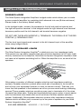
INSTALLATION CONSIdERATIONS
CABLE ANd wIRE
It will be easier to recongure or troubleshoot your system in the future if you
label the cables and wires for their destination or source, rather than which
terminal of the Niles System Integration Amplier
®
they are connected to.
The Niles System Integration Amplier
®
connects to your sources via shielded
line level audio cables with RCA phono plugs. Use high quality cables with your
Niles amplier for the lowest possible noise and best overall performance. Your
Niles dealer can recommend the proper cable.
The Niles System Integration Amplier
®
connects to your speakers using 2
conductor speaker wire. For most applications, we recommend you use 16
or 18 gauge wire. For wiring runs longer than 80 feet, we recommend 14
gauge wire. The binding posts of the Niles System Integration Amplier
®
will
accommodate up to 12 gauge wire. Larger sizes can be accommodated by
attaching banana plugs to the wire. Note that the binding posts accept dual
banana or single banana connectors.
SPEAKER 6
L+ L- R- R+
AM PLIFIER
L+ L- R- R+ L+ L- R- R+ L+ L- R- R+ L+ L- R- R+ L+ L- R- R+
SPEAKER 5 SPEAKER 4 SPEAKER 3 SPEAKER 2
L+ L- R- R+
SPEAKER 1
CONSTA NT
PRO TECTION
ON OFF
Niles Audio
Corporation,Inc.
Miam i, Florida USA
NILES
Systems Integration Amplif ier
®
TECh TIp
Wire size is expressed by its AWG (American
Wire Gauge) number. The lower the number,
the larger the wire, i.e. twelve AWG is physically
larger than fourteen AWG.

11
NILES AUDIO CORPORATION – 1-800-BUY-HIFI – 1-760-710-0992
2 Channel, BridgaBle Power amPlifiers
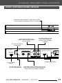
FRONT ANd REAR pANEL dETAILS
SI -250
Systems Integration Amplif ier
®
Front panel “Master Power” switch turns off the
entire amplier, including the Turn-On circuitry.
SI-250
Systems
Integration
Amplif ier
®
TURN ON MODE
AUDIO SENSE
CONSTANT
3-30V
AC/DC
TRIGGER
INPUT
12V
CONTROL
OUT
L R
L
R
BUS
OUTPUT
FOR
BRIDGED
MODE
L
R
LEVELS
MAIN BUS
INPUT
STEREO BRIDGED
CLASS 2 WIRING
LEFT
RIGHT
This device complies with Part 15 of the FCC Rules.
Operation is subject to the following two conditions:
(1) this device may not cause harmful interference, and
(2) this device must accept any interference received,
including interference that may cause undesired
operation.
This Class B digital apparatus complies with Canadian
ICES-003.
Cet appareil numérique de la classe B est conforme à la
norme NMB-003 du Canada.
Niles Audio, Carlsbad, California, USA
Designed and Engineered in the U.S.A. Made in China
T5AL, 250V
Serial No.
CAUTION: replace only with same type and rating of fuse.
ATTENTION: remplacer uniquement avec le même type
et calibre du fusible.
Minimum impedance:
2.66 Ω (stereo mode)
4 Ω (bridged mode)
100-120V / 220-240V~
50 / 60Hz 200W
Main Inputs enable you to
route a stereo line level source
to the amplier.
3.5 mm mini-jack for
voltage input
3.5 mm mini-jack for
12V DC control output
“Turn-On Mode”
switch
Bridge mode switch
Level Adjustment screws enable you to
preset the maximum system volume (or
match levels with another amplier)
Cascade Outputs of the
main input enable you
to daisy chain multiple
ampliers

12
WWW.NILESAUDIO.COM
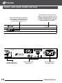
FRONT ANd REAR pANEL dETAILS
SI -250
Systems Integration Amplif ier
®
Power LED illuminates to conrm
the amplier is connected to a
live AC power outlet and that the
master power switch is on
Bicolor Status LED illuminates
“green” when the amplier circuitry
has been turned on by the Turn-On
circuits, and illuminates “red” to
indicate activation of the amplier’s
built-in protection circuitry
SI-250
Systems
Integration
Amplif ier
®
TURN ON MODE
AUDIO SENSE
CONSTANT
3-30V
AC/DC
TRIGGER
INPUT
12V
CONTROL
OUT
L R
L
R
BUS
OUTPUT
FOR
BRIDGED
MODE
L
R
LEVELS
MAIN BUS
INPUT
STEREO BRIDGED
CLASS 2 WIRING
LEFT RIGHT
This device complies with Part 15 of the FCC Rules.
Operation is subject to the following two conditions:
(1) this device may not cause harmful interference, and
(2) this device must accept any interference received,
including interference that may cause undesired
operation.
This Class B digital apparatus complies with Canadian
ICES-003.
Cet appareil numérique de la classe B est conforme à la
norme NMB-003 du Canada.
Niles Audio, Carlsbad, California, USA
Designed and Engineered in the U.S.A. Made in China
T5AL, 250V
Serial No.
CAUTION: replace only with same type and rating of fuse.
ATTENTION: remplacer uniquement avec le même type
et calibre du fusible.
Minimum impedance:
2.66 Ω (stereo mode)
4 Ω (bridged mode)
100-120V / 220-240V~
50 / 60Hz 200W
Binding posts for
speaker connections
IEC receptacle for
AC power cord
Replaceable main
power fuse

13
NILES AUDIO CORPORATION – 1-800-BUY-HIFI – 1-760-710-0992
2 Channel, BridgaBle Power amPlifiers
INSTALLATION
SETTING ThE TURN-ON mOdE SwITCh
The Niles System Integration Amplier
®
has three turn-on modes. Select which
mode you desire by sliding the mode switch. See Installation Considerations on
page 6 for more information about each of the turn-on modes. Audio sense is
the factory default setting.
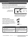
CONTROL OUTpUT
This terminal provides a 12V DC signal
suitable for triggering Niles automated
switchers, some motorized screens, some
electric curtain controls, etc. The trigger
voltage is present only when the amplier is
active or “on”. When the amplier turns “off”,
the 12 Volt signal is off.
STEP DESCRIPTION
STEP DESCRIPTION
1. Check the requirements of the device you
want to control.
The control output has a maximum
current capability of 12V DC 150 mA.
2. Connect the 3.5 mm Jack to the control
output maintaining proper polarity
(tip = +).
Niles makes an accessory cable plug
FG00933.
100-120V / 220-240V~
50 / 60Hz 600W
Systems
Integration
Amplif ier
®
TURN ON MODE
AUDIO SENSE
CONSTANT
3-30V
AC/DC
TRIGGER
INPUT
12V
CONTROL
OUT
L R
L
R
BUS
OUTPUT
FOR
BRIDGED
MODE
L
R
LEVELS
MAIN BUS
INPUT
STEREO BRIDGED
CLASS 2 WIRING
LEFT RIGHT
This device complies with Part 15 of the FCC Rules.
Operation is subject to the following two conditions:
(1) this device may not cause harmful interference, and
(2) this device must accept any interference received,
including interference that may cause undesired
operation.
Niles Audio, Carlsbad, California, USA
Designed and Engineered in the U.S.A. Made in China
T5AL, 250V
Serial No.
CAUTION: replace only with same type and rating of fuse.
ATTENTION: remplacer uniquement avec le même type
et calibre du fusible.
Minimum impedance:
2.66 Ω (stereo mode)
4 Ω (bridged mode)
Slide the switch with
your ngernail or a 1/8”
slotted screwdriver blade
TIP: To conserve energy set the TURN ON mode to
either AUDIO SENSE or TRIGGER INPUT. Use of the
CONSTANT mode will prevent the amplifier from
turning off when not in use wasting energy.

14
WWW.NILESAUDIO.COM
INSTALLATION
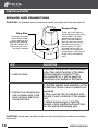
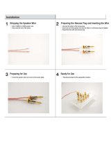
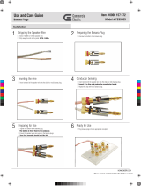
SpEAkER wIRE CONNECTIONS
CAUTION! All speaker wire connections must be made with the amplier off.
CAUTION! Avoid even a single strand of wire touching the chassis or another
connector.
STEP DESCRIPTION
1. Label all wires.
If you label the wires for their destination,
rather than which terminal of the Niles
System Integration Amplifier
®
they
are connected to, it will be easier to
reconfigure your system in the future.
2. Connect one stripped wire
end or banana plug to the
black terminal and one to
the red terminal.
A. Split the speaker wire insulation so that
at least two inches of each conductor are
separated.
B. Strip one half inch of insulation from
the end of each conductor of the speaker
wire.
C. Attach banana plugs or twist the
strands of wire together and insert them
into the appropriate binding post.
Bare Wire
Unscrew the red or
black plastic knob,
insert the bare wire
end into the opening,
and then tighten the
knob until the wire is
securely clamped
Banana Plugs
There are many types of
banana plugs, some crimp,
some solder. The Niles
gold banana plug has 3
quick-connect binding
post for the bare wire on
the body of the plug. A
banana plug is simply
inserted into the jack at
the end of the amplier’s
binding post. Dual banana
plugs will t the binding
post.

15
NILES AUDIO CORPORATION – 1-800-BUY-HIFI – 1-760-710-0992
2 Channel, BridgaBle Power amPlifiers
INSTALLATION
LINE LEvEL AUdIO INpUT
CAUTION! The amplier must be off whenever you make changes to the input
connections.
CASCAdE AUdIO OUTpUTS
The “Cascade Audio Outputs” enable you to connect another amplier to
your preamplier output. The connectors are gold-plated RCA phono jacks.
Connect them to another amplier’s inputs with a standard audio patch cable.
The outputs are not buffered; if you wish to daisy-chain more than 5 Niles
System Integration Amplier
®
ampliers you will need a Niles AVDA-3 buffered
distribution amplier. A single AVDA-3 will allow you to daisy-chain 5 ampliers
from each of its three outputs, allowing for as many as 30 Niles System
Integration Amplier
®
models to be fed from the same master preamplier. If
your preamp has a vacuum tube output stage, you must use a Niles AVDA-3 to
drive more than a single Niles System Integration Amplier
®
.
STEP DESCRIPTION
1. Label all of the interconnecting cables
for the sources they connect to.
Use audio patch cables with RCA
phono plugs attached to the ends.
2. Connect the sources by inserting the
RCA plugs into the amplifier’s jacks.
Connect outputs from your sources
to inputs on the amplifier. Never
connect a source or preamplifier’s
input (e.g., record inputs) to
the inputs of your Niles System
Integration Amplifier
®
.

16
WWW.NILESAUDIO.COM
INSTALLATION
AC pOwER pLUG
CAUTION! Typically a preamp/receiver’s switched outlet is not rated for a power
amplier. The SI- 250, the SI-2100 and the SI-2150 draw 200 watts, 300 watts,
and 400 watts maximum from an AC wall outlet respectively. Use a dedicated
AC wall outlet along with the amplier’s auto turn on circuit to ensure adequate
power.
STEP DESCRIPTION
1. Plug the female IEC socket of the
supplied AC power cord (the supplied
power cord is designed for 120V AC
wall outlets), or use an appropriate
IEC AC power cord to match the
electrical wall outlet you are using
(e.g. 240V AC), into the IEC receptacle
on the rear of the amplifier.
Just like a computer or printer, the
Niles System Integration Amplifier
®
has an AC cord which unplugs
either at the amp or at the wall for
your convenience.
2. Plug the male end of the AC power
cord into a correctly grounded wall
outlet.
If you use a grounded power strip,
surge suppressor or extension
cord, verify that proper ground is
maintained.

17
NILES AUDIO CORPORATION – 1-800-BUY-HIFI – 1-760-710-0992
2 Channel, BridgaBle Power amPlifiers
OpERATION
pOwER SwITCh
The front panel switch is a master or “vacation” power switch. No matter which
turn-on mode you have selected, the master power switch will turn off all
circuitry including the sensing circuitry. If you will not be using the amplier for
an extended period of time, turn the master power switch “Off” (push button
switch out). When you would like to return to normal operation, turn the switch
“On” (push button switch in).
Important Notes: Equipment is not completely disconnected from main power
source when power switch is in the “OFF” position.
pOwER LEd
The power LED indicates that the AC cord is plugged into a working AC power
receptacle and that the power switch is in the “On” position.
BICOLOR STATUS LEd
The bicolor Status LED illuminates “green” when the amplier circuitry has been
turned on by the Turn-On circuits, and illuminates “red” to indicate activation of
the amplier’s built-in protection circuitry due to either a fault in the wiring or the
speaker, or with the Niles System Integration Amplier
®
itself.
LEvEL AdjUSTmENT SCREwS
The rear panel level adjustment screws allow you to adjust the level of the Niles
System Integration Amplier
®
relative to other ampliers in your system. Use
a 1/8” slotted screwdriver to adjust the screws. If the Niles System Integration
Amplier
®
is the only amplier in your system, leave the screws at their factory
default setting (12:00 position).
CLEANING ANd mAINTENANCE
The internal parts of the Niles System Integration Amplier
®
are electronic
and require no maintenance. Once a year it is appropriate to twist the RCA
connectors on each input to remove corrosion and improve conductivity. You
can clean the amplier with soft cloth or paper towel dampened with water or a
mild detergent. Do not use any spray-type, abrasive cleaners on the amplier.

18
WWW.NILESAUDIO.COM
TROUBLEShOOTING GUIdE
When there is a problem, consult this guide rst. If the problem persists, or you
have additional questions, call your local Niles dealer or Niles Technical Support
at 1-800-BUY-HIFI (289-4434) or (760) 710-0992. The most common problems
relate to hook up. Call from your telephone extension nearest the system.
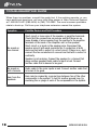
Symptom Possible Causes and Test Procedure
No sound on
one channel
Short circuit or loose wire at the speaker or amplifier terminals.
Check that the connections are secure and that there are no
loose strands of wire crossing from the positive to the negative
terminals at the back of the amplifier and /or the speaker.
Short circuit or a break in the speaker wire. Disconnect the
speaker wire at both ends, separate the 2 conductors at both
ends and test with a meter for a short circuit. If there is no
short,
connect the two conductors at one end and test with a meter for
continuity.
Speaker is not working. Connect the speaker to a channel that
plays another speaker. Audio cable to input is bad. Connect
another cable that is known to be good.
No sound on
both channels
Audio cable to the main inputs is bad. Connect another cable that
is known to be good.
Hum from the
speakers
Hum may be caused by a ground loop between two of the other
components in the system. To test for another ground loop, try
reversing the ac plugs of each of the components in the system.

19
NILES AUDIO CORPORATION – 1-800-BUY-HIFI – 1-760-710-0992
2 Channel, BridgaBle Power amPlifiers
TROUBLEShOOTING GUIdE
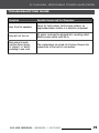
Symptom Possible Causes and Test Procedure
Hum from the speakers
Check for faulty cables, faulty source material, an
ungrounded phono system or a defective component.
Amp will not turn on
AC power cord must be plugged into a working outlet.
Master power switch must be on.
Bass sound is weak
and the stereo image
is “phasey” or “blurry”
sounding in one room
The loudspeakers are wired out of phase. Reverse the
connections at the back of one speaker.

20
WWW.NILESAUDIO.COM
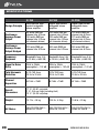
SI-250 SI-2100 SI-2150
Design Principle
Fully discrete, high
current bridgeable
stereo amplifier
Digital, high current
bridgeable stereo
amplifier
Digital, high current
bridgeable stereo
amplifier
Continuous
Average Power
Output
50 watts RMS per
channel into 8 Ohms,
100 watts RMS per
channel into 4 Ohms
(all channels driven)
100 watts RMS per
channel into 8 Ohms,
220 watts RMS per
channel into 4 Ohms
(all channels driven)
150 watts RMS per
channel into 8 Ohms,
270 watts RMS per
channel into 4 Ohms
(all channels driven)
Continuous
Average Power
Output Bridged
225 wats RMS per
channel into 8 Ohms
400 wats RMS per
channel into 8 Ohms
550 wats RMS per
channel into 8 Ohms
Frequency
Response
Bandwidth from 5 Hz
to 25 kHz (=0dB/-3B)
Bandwidth from 5 Hz
to 25 kHz (=0dB/-3B)
Bandwidth from 5 Hz
to 25 kHz (=0dB/-3B)
Signal to Noise
Ratio
20Hz to 20kHz
unweighted > 102 dB
20Hz to 20kHz
unweighted > 102 dB
20Hz to 20kHz
unweighted > 102 dB
Total Harmonic
Distortion
0.2% THD from
20 Hz to 20 kHz
0.2% THD from
20 Hz to 20 kHz
0.2% THD from
20 Hz to 20 kHz
Channel
Separation
@ 1kHz >70dB @ 1kHz >70dB @ 1kHz >70dB
Overall
Dimensions
17 ¼” (43.81 cm) wide
2 ¼” (5.6 cm) high (including feet)
13 ½” (34.35 cm) deep
Weight
10.7 lb., 4.8 kg. 10.8 lb., 4.9 kg. 10.8 lb., 4.9 kg.
AC Mains:
100-120/220-240 V~,
50/60 Hz, 200 W
100-120/220-240 V~,
50/60 Hz, 300 W
100-120/220-240 V~,
50/60 Hz, 400 W
SpECIFICATIONS
Page is loading ...
Page is loading ...
Page is loading ...
Page is loading ...
-
 1
1
-
 2
2
-
 3
3
-
 4
4
-
 5
5
-
 6
6
-
 7
7
-
 8
8
-
 9
9
-
 10
10
-
 11
11
-
 12
12
-
 13
13
-
 14
14
-
 15
15
-
 16
16
-
 17
17
-
 18
18
-
 19
19
-
 20
20
-
 21
21
-
 22
22
-
 23
23
-
 24
24


Niles SI-2100 User manual
- Category
- Audio amplifiers
- Type
- User manual
Ask a question and I''ll find the answer in the document
Finding information in a document is now easier with AI
Related papers
Other documents
-
Lepai LP-2020TI User manual
-
 Commercial Electric Y611393 User manual
-
 Commercial Electric Y293035 Operating instructions
-
Niles Audio SI-275 User manual
-
ATI AT6000 SIGNATURE SERIES Owner's manual
-
Orion ORGLI100 Owner's manual
-
-
Harman Kardon PA 2000 Owner's manual
-
-
Pyramid PSV40 User manual

