
Frymaster, a member of the Commercial Food Equipment Service Association, recommends
using CFESA Certified Technicians.
*8196606*
24-Hour Service Hotline
1-800-551-8633
Price: $6.00
819-6606
NOV 10
UHC-HD
Service, Parts Manual for 6, 3-Row Models

NOTICE
IF, DURING THE WARRANTY PERIOD, THE CUSTOMER USES A PART FOR THIS ENODIS
EQUIPMENT OTHER THAN AN UNMODIFIED NEW OR RECYCLED PART PURCHASED DIRECTLY
FROM FRYMASTER DEAN, OR ANY OF ITS AUTHORIZED SERVICE CENTERS, AND/OR THE
PART BEING USED IS MODIFIED FROM ITS ORIGINAL CONFIGURATION, THIS WARRANTY WILL
BE VOID. FURTHER, FRYMASTER DEAN AND ITS AFFILIATES WILL NOT BE LIABLE FOR ANY
CLAIMS, DAMAGES OR EXPENSES INCURRED BY THE CUSTOMER WHICH ARISE DIRECTLY
OR INDIRECTLY, IN WHOLE OR IN PART, DUE TO THE INSTALLATION OF ANY MODIFIED PART
AND/OR PART RECEIVED FROM AN UNAUTHORIZED SERVICE CENTER.
THE CABINET IS NOT SUITABLE FOR OUTDOOR USE. WHEN OPERATING THIS UNIT, IT
MUST BE PLACED ON A HORIZONTAL SURFACE.
THE CABINET IS NOT SUITABLE FOR INSTALLATION IN AN AREA WHERE A WATER JET
CAN BE USED. THIS APPLIANCE MUST NOT BE CLEANED WITH A WATER JET.
FOR YOUR SAFETY
DO NOT STORE OR USE GASOLINE OR OTHER FLAMMABLE VAPORS AND LIQUIDS IN
THE VICINITY OF THIS OR ANY OTHER APPLIANCE.
DO NOT OPERATE OR SERVICE THE CABINET WITHOUT FIRST READING THIS MANUAL.
DO NOT OPERATE THE CABINET UNLESS IT HAS BEEN PROPERLY INSTALLED AND
CHECKED.
DO NOT OPERATE THE CABINET UNLESS ALL SERVICE AND ACCESS PANELS ARE IN
PLACE AND PROPERLY SECURED.
DO NOT ATTEMPT TO REPAIR OR REPLACE ANY COMPONENT OF THE CABINET UNLESS
ALL POWER TO THE UNIT HAS BEEN DISCONNECTED.
USE CAUTION WHEN SETTING UP, OPERATING, OR CLEANING THE CABINET TO AVOID
CONTACT WITH HEATED SURFACES.
USE CAUTION WHEN LIFTING THE UHC-D. THE UNIT WEIGHS 200 POUNDS. THREE TO
FOUR PEOPLE, USING STANDARD SAFE LIFTING PRACTICES, WILL BE NECESSARY TO
HANDLE THE CABINET.

Table of Contents
Theory of Operation 1-1
Service/Software Procedures 2-1
Troubleshooting 3-1
Illustrated Parts List 4-1
Wiring Diagrams 5-1

Cabinet Service Procedures
1-1
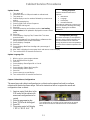
1 Functional Description
1.2 Theory of Operation
The cabinet operates on 208-250VAC 50 or 60 cycle single-phase power. The main switch activates
a relay, which supplies line voltage to two distribution boards, three cooling fans and a power
supply. The power supply provides 5VDC to the master control board and the distribution boards.
A ribbon cable connects the master control board to both distribution boards. Ribbon cables also
connect the distribution boards to the displays. The resistance of RTD’s, attached to the heater
plates, is monitored by the distribution boards. The board switches power through solid-state relays
to the heater plates when the resistance, which is used as an indicator of temperature, falls out of the
range for the product held in the cabinet.
The switch, relay, master control, master control board, LON board, LON filter, cooling fans and
power supply are mounted under the top of the unit. The cabinet is programmed using the key pad
on the front bezel.
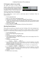
Timer keys
Note: Theillustrationsfor
theseserviceprocedures
areofthe6‐rowfullsize
UHC
‐
HD
.
Row Mode key
Timer: displays on row
board remaining time for
all active timers.
Temperature: displays on
row board plate
temperature, alternating
between top and bottom.
Power switch
Timer key
Master Control Display

Cabinet Service Procedures
1-2
1.3 Start Up Indicators and Test Points
Upon startup, the cabinet beeps. LED’s on the distribution boards flash. The displays show the
version number of the cabinet’s firmware and then the row’s status.
Distribution boards
shown with ribbon
cables removed.

Cabinet Service Procedures
2-1
2 Service Procedures
DANGER: Failure to disconnect power from the unit before servicing could result in serious
injury or death. The cabinet power switch DOES NOT disconnect all incoming power to the
cabinet.
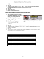
2.1 Updating Software/Capturing Configurations
The five sections of software on the cabinet can be updated individually. To ensure compatibility between cabinet
software and replacement boards, the software should be updated to the latest version at any board replacement. Follow
the directions below.
Software updates use the master control display to enter programming codes, scroll to areas to be revised, respond to
questions and exit. The control is annotated above. The arrow and OK buttons are illuminated when active.
Check Existing Versions
1. With the unit powered up, press the programming key.
2. Screen scrolls Enter Access Sequence.
3. Enter 090809 on keypad.
4. Press OK.
5. Scroll with arrow keys to view all software revision numbers:
• Main
• Boot Loader
• Master Display
• Distribution Board
• Row Display
6. Press OK.
Fig.1:Thesides
areheldinplace
byscrewsnear
thebaseofthe
unitoneachside.
Fig.2:Tabsinthetopcapextendto
holesinthecabinet.Thetopissecured
withatthetabswithscrews.
Programming key:
Press prior to entering
programming code.
OK: Press to confirm
choices.
Arrows: Scroll to
choices.
Power Switch: Cycle
power between each
revision u
p
date.
Keypad: Enter
programming
d
NOTE: If the master control
displays an error message
during the install process, turn
the cabinet off for 30 seconds
and back on. Repeat install
steps.

Cabinet Service Procedures
2-2
Update: Boards
1. Turn power off.
2. Insert flash drive in USB port located on cabinet bezel.
3. Turn power on.
4. Cabinet displays version numbers followed by current menu
setting.
5. Press programming key.
6. Screen scrolls Enter Access Sequence.
7. Enter 98765 with keypad.
8. Press OK.
9. Scroll with arrow key until software section (see loading
sequence box) to be updated is displayed on master control
board.
10. Press OK.
11. Screen displays Copying Files, Please Wait. This takes
several minutes.
12. Screen messages will vary, depending on software section
being installed. Follow screen instructions.
13. Screen displays Complete.
14. Press OK.
15. Screen displays Main Boot Loading and a percentage of
completion.
16. After 100% is displayed, screen goes blank and returns to menu display.
17. Turn cabinet off for 30 seconds and back on.
Update: Language File
1. With the unit on, press program button.
2. Enter 090709 with the keypad.
3. Press OK.
4. Screen displays Reconfigure OK or Cancel.
5. Press OK.
6. Screen displays Please Wait Lang Bin.
7. Screen displays 9 files copied.
8. Press OK.
9. Screen returns to normal display.
10. Turn cabinet off for 30 seconds and back on.
Capture Cabinet Menus/Configurations
The menu items and cabinet configurations in a cabinet can be captured and used to configure
cabinets with identical software setups. Follow the instructions below to capture the menus and
configuration from a cabinet.
1. Insert an empty flash drive in the
USB socket on the cabinet with
menus and configurations to be
copied.
2. Press the programming key.
3. Enter 759248 with the keypad.
4. Press OK.
5. The master control will display
Copy from UHC to
LoadingSequence
Softwareshouldbeloadedinthis
sequence:
• MainBoard
• Language
• RowDisplay
• DistributionBoards
Ifthesoftwareupdateonlyinvolvesafew
ofthecomponents,followingtheloading
sequence,skippingtheunneeded
com
p
onent.
IncompatibilityMessage
Thecabinetcandisplayanincompatibility
messageduringsoftwareupgrades.The
buttonswillremainactive.Followthe
loadingsequenceandtheincompatibilityis
correctedasthesoftwarecomponentsare
loaded.
The configuration of a cabinet can be captured on an empty
flash drive for transfer to cabinets with the same software
setup.

Cabinet Service Procedures
2-3
USB.
6. Press OK.
7. The master control displays Please Wait… as files are transferred to the flash drive,
changing to the number of files copied when the process is complete.
8. Press OK.
9. Remove flash drive.
10. Cabinet returns to normal display.
Configure Cabinet with Menu/Configuration Captured on another Cabinet
1. Place a flash drive with only a captured
menu/cabinet configuration in the root file
into the USB port of a cabinet to be
identically configured.
2. Press the programming key and enter
090709 with the keypad.
3. Press OK.
4. The master control will display
Reconfigure OK or
Cancel.
5. Press OK.
6. The master control will display Please wait… as the files are updated, changing to the
number of files copied.
7. Press OK.
8. The cabinet will return to the original menu setting, changing row position displays to match
items introduced with the configuration transfer.
Cabinet Access Codes
Code Function
759248 Capture cabinet configuration to flash drive
98765 Load software updates from USB drive
1955 Enter manual programming mode (see operation manual).
4557 LON Works service pin
090809 View software versions
1111 Service test mode
090709 Update language file
A cabinet configuration can be transferred to multiple
cabinets with a captured configuration held on a flash
drive.

Cabinet Service Procedures
2-4
2.2 Placing the cabinet in Service Mode
The cabinet can be put in service mode, a
diagnostic settings which allows the heater plates
to be controlled individually, brightness settings on
the displays adjusted and re-addressing for unique
arrangements of bezels. Follow the steps below :
Switching Heater Plates Off Individually
When troubleshooting, it may be useful to switch heater plates off individually. Follow the
instructions below:
1. Press the programming key.
2. Enter 1111 at the Enter Access Sequence prompt.
3. The screen will scroll Row 1 Top Heater Off; pressing OK turns it back on.
4. Voltage can be measured between the plate-specific heater leads on the distribution board
and the common block to the right of the distribution board as the heater plates are switched,
individually, on and off.
5. Scroll to other plates with WX.
6. Ensure the plates are on before backing out of the Service Mode with the /.
Adjusting Display Brightness
When multiple row positions are timing the same item, the display with the least remaining time is
the brightest. All others are dimmer as are positions not actively timing a product. The relative
brightness of the bright display and the dim display can be adjusted. Follow the instructions below:
1. Press the programming key.
2. Enter 1111 at the Enter Access Sequence prompt.
3. Press OK.
4. The screen will scroll Row 1 Top Heater Off.
5. Scroll with X through all the Heater Plate prompts until the screen displays Press OK to
Adjust Bright Row Display.
6. Press OK.
7. The cabinet’s row displays become
Decrease Increase 88888 20
8. Press the timer button next to the Decrease display to lessen the brightness; the number
displayed at the right will decrease. Press the timer button next to the Increase display to
increase the brightness; 20 is the maximum.
9. Press OK. The display becomes Adjust Dim Intensity. The cabinet’s row displays become
Decrease Increase 88888 03
10. Press the timer button next to the Decrease display to lessen the brightness; the number
displayed at the right will decrease. Press the timer button next to the Increase display to
increase the brightness; 1 is the minimum.
11. Press OK.
12. Cabinet returns to menu display.

Cabinet Service Procedures
2-5
Readdressing the Cabinet
Addressing, or assigning a position-specific component such as a display or distribution board, is
done automatically by the cabinet on startup. Communication errors can occur on start-up after a
board installation however. If so, follow the instructions below to readdress the cabinet. This process
can also be used during troubleshooting when displays are connected out of synch with their
associated bezel on the same row level.
1. Press the programming key.
2. Enter 1111 at the Enter Access Sequence prompt.
3. The screen will scroll Row 1 Top Heater Off.
4. Scroll with X through all the Heater Plate prompts until the screen displays Press OK to Re-
Address.
5. Press OK.
6. Screen Displays Please Power Cycle Off.
7. Turn the cabinet off and back on.
8. The cabinet will start in the normal start-up sequence.

Cabinet Service Procedures
2-6
2.3 Accessing the Electronic Components
1. The component shelf is accessed by removing two screws on each side of the unit (Fig. 1).
2. Lift and remove the sides, which exposes screws that hold the top in place (Fig. 2).
3. The components are annotated below (Fig. 3).
All the components are readily removed. There are no replaceable components on the circuit boards.
2.4 Circuit Board LED Diagnostics
Master Control Board:
• HB LED is a heartbeat; should
be flashing when in the normal
in- use mode. Flash rate is not
critical.
• ACT LED similar to HB but
flashes at a faster rate.
• OK LED toggles each time a valid communication packet is sent and received. Normally a
very fast flicker.
Rela
y
Fans: are specific to
regions of the cabinet
and ducted to direct
the air flow.
Fig.4:MasterControlBoardLED's
Figure 3
Master
Display
Board
LON
filter
Master Control
Board
LON board
LON
filter
Power
supply
Cooling
fans
NOTE:Thecoolingfans
restonducts,andcool
specificregionsofthe
cabinet.

Cabinet Service Procedures
2-7
• ERR LED toggles when a communication error is detected; it’s not unusual to see a flash,
but regular flashing means communications problems.
• LED5 and LED6 used for programming/debugging; have no diagnostic function.
• LED7 When lit, the master control is executing a time or temp query operation on the front
side.
• LED8 When lit, the master control is executing a time or temp query operation on the back
side.
Distribution Board
• HB LED is a heartbeat LED; toggles on / off to indicate
processor is running.
• ACT LED flashes when it receives a valid communication
packet; it should be flashing every few seconds or faster.
• LED3 Toggles if there is a communications error on a packet
directed to the distribution board. Can flash on occasion;
shouldn’t flash regularly.
• LED1 flashes if there is voltage being applied to one or more
heaters on that distribution board; one or more plate is calling
for heat.
2.5 Tests
2.5.1 Power Supply
1. Disconnect power and check all terminals and
connections for loose or disconnected wires.
2. Apply power and check for 5VDC at the power-in
terminal on the distribution board and chassis
ground.
2.5.2 RTD
1. Remove the leads from the suspect RTD and test for
resistance. Selected temperatures and resistances are
show in chart at right.
NOTE: After testing, reconnect all leads to their
original positions.
2.5.3 Distribution Boards
1. Check for line voltage between the heater plate
terminal on the board and the terminal block for the
Sensor
(°F)
Resistance
Sensor
(°C)
60 106.065 15.55
70 108.224 21.11
80 110.380 26.66
90 112.532 32.22
100 114.680 37.77
110 116.825 43.33
120 118.966 48.88
130 121.104 54.44
140 123.239 60.00
150 125.369 65.55
160 127.496 71.11
170 129.620 76.66
180 131.740 82.22
190 133.856 87.77
200 135.969 93.33
210 138.078 98.88
220 140.184 104.44
230 142.286 110.00
240 144.385 115.55
250 146.480 121.11
260 148.570 126.66
RTD resistance chart
Fig.5:DistributionBoardLED's

Cabinet Service Procedures
2-8
suspect heater. Note: Line voltage is only seen when the row is calling for heat.
2. Check for line voltage between the
power input terminal and the terminal
block.
3. Check for +5VDC at the power-in
terminal and the terminal block for the
power supply.
NOTE: After testing, reconnect all
connections to their original positions.
2.5.4 Display
1. Remove power from unit.
2. Connect the ribbon cable from a
suspect display to the connector of a
properly working display to isolate the
problem to the display or the
distribution board.
3. Reapply power to cabinet.
2.5.5 Shorted Triac
1. Turn the suspect row off and measure
voltage between the suspect heater lead on the distribution board and the terminal block. With
the row off, there should be no line voltage. If the triac is shorted, you will measure AC line
voltage. If the triac is half waving, you will get DC voltage of approximately one-half the line
AC voltage.
2.5.6 Heater Plate
1. Disconnect power to the cabinet. Remove side and top panels. Disconnect the black heater lead
and the RTD leads (brown and red) of the suspect plate from distribution board. Measure
resistance of the heater from the black lead to any terminal on the white terminal block.
Resistance should be 140-150 ohms.
2. Measure resistance across the brown and red RTD leads. Resistance must be within a range of
104-148 ohms. Resistance at room temperature is approximately 107 ohms. See chart on Page
2-4 for resistance at different temperatures. If either resistance is incorrect, replace the heater
plate.
2.5.7 Display Meanings
1. ROW TEMP HIGH OR ROW TEMP LOW and no audible alarm. This is normal when
the row is changing temperature in association with a menu change.
2. LLLL means the RTD indicates a temperature below 50°F (10°C). Unit will automatically heat
at 20 percent until temperature is above 50°F (10°C), then operate normally.
Fig.6:Distributionboardshownwithdisplaycablesremoved.

Cabinet Service Procedures
2-9
Fig.7:Twoscrews(seearrows)atthe
baseofeachsideofthecabinetsecure
thesides.
3. HHHH means RTD indicates the temperature is above 255°F (124°C), but below "Open" circuit
resistance, which causes SENS ALARM.
4. UHC VERSION _ _ _ (version number will vary)
appears for five seconds when the unit is turned on.
5. The cabinet also displays a variety of error messages, which are
shown on page 3-1.
2.6 Removing/Replacing Bezels
1. Remove power from unit.
2. Remove screws at the base of each side and remove side
panels. (See figure 7.)
3. Unplug the bezel from the distribution board.
4. Plug the replacement bezel into the distribution board,
return power to the unit and test the bezel/cabinet for
accurate operation.
5. Remove replacement bezel and remove power from the unit.
6. Loosen the hex nut which secures the row and remove the allen screw, which holds the
bezel. Also remove, if present, the small bezel-securing screw. (See photo below.)
7. Push, if necessary, on the mounted bezel through the access port in the inner panel to
loosen the bezel. (See Figure 8 below.)
8. Remove bezel; clean and degrease the groove in the heater plate.
9. Route ribbon cable for the new bezel through the inner panel of the cabinet and press the
new bezel into place. Ensure it is firmly seated and tighten hex nuts and replace allen
screws.
10. Return sides and reposition cabinet for operation.
Fig.8:Loosenthehexboltand
removetheallenscrew(arrows,
upperphoto).Somerowpositions
mayhaveanadditionalscrew
securingthebezeltothecabinet
(lowerphoto).Pushthroughthe
accessport(arrow,upperphoto),if
necessary,toremovethebezel
fromthecabinet.

Cabinet Service Procedures
2-10
2.6. 1 Removing/Replacing a Distribution Board or Communication Board
1. Remove power.
2. Remove and mark the wires on the faulty component.
3. Remove the board by lifting it from its
standoffs.
4. Position the new board and attach
wires.
5. Reapply power.
6. Run readdress steps on page 2-4.
2.6.2 Removing a Row
1. Remove the sides and top as shown in
earlier steps. Disconnect the faulty row
from the distribution board, and
terminal block.
2. Remove the bezels on each end of the
affected row, as shown in earlier steps,
and the necessary adjacent bezels to
remove the row.
3. Remove wire wraps from wiring
harness holding heater and control
wires for affected row.
4. Lifting slightly, carefully slide the malfunctioning row out of the cabinet. Do not allow the row
to contact or damage the controls of the unit below (Fig. 9).
2.6.3 Replace Heater Plate/RTD
1. Remove row as shown above.
2. Run your fingers around the outside surface of the row assembly. There are four raised areas.
These are the setscrews, which hold the heater plate to the spacer. Punch holes in the insulation,
directly above the location of the setscrews. (Fig. 10, 11).
3. Use an allen wrench to loosen the four spacer-setscrews along the edges of the plate.
4. Slide the malfunctioning plate out of the spacer.
5. Slide the replacement plate into position. Make
sure the plate is inserted squarely. Tighten set
screws.
6. Route the wires to one end of the row and wire tie
the power wires together. Also wire tie the RTD
wires together. Stand the row on the opposite end
adjacent to the cabinet and feed the wires into the
cabinet.
7. Carefully slide the row far enough into the cabinet
to be stable.
8. On the opposite side, reach into the cavity and
direct the wires through the appropriate grommets
to reach the power and RTD connections on the distribution board.
Fig.10,11:Findthesetscrewsunderthefoil
insulationandpushthroughwithanallenwrench.
Fig.9:Arowisshownpartiallyremovedfromthecabinet.

Cabinet Service Procedures
2-11
9. Slide the row assembly completely into the
cabinet and return the spacers between the heater
plates. Ensure the row is evenly positioned in the
cabinet. There must be sufficient space to allow
the bezel tabs to fit between the outside row plate
and the cabinet interior wall.
10. Replace the bezels.
CAUTION
Ensure the heater plate setscrews are tightened securely to the spacer.
Tightening the setscrews will ensure the plate is properly grounded.
Fig.12:Theheaterplateslidesfromtheinsulation.

Cabinet Troubleshooting
3-1
The master control display and the row displays show error messages when there is a problem. The
messages are shown in the matrix below along with possible causes and diagnostic tests.
Error Message Cause Tests
Call service row display
error
Rownumberalsodisplayed*
Themastercontrolboardhaslost
communicationwiththespecified
board.
• Turnthecabinetoffandbackon.
• Ensuretherearenosoftware
incompatibilities.
• Inspectribboncableconnections.
Call service distribution
board 0 error*
Themastercontrolboardhaslost
communicationwiththetop
distributionboard.
• Adisplayconnectioncanproduce
thisdisplay.Beforereplacinga
distributionboard,removepower
fromtheunitanddisconnectthe
displaysfromtheaffected
distributionboard.Returnpower
totheunitand,oneata
time,plug
inthedisplays,cyclingpowereach
time.Iftheproblemisdisplay‐
relateditwillgoawaywiththe
affecteddisplaydisconnected.
Call service distribution
board 1 error*
Themastercontrolboardhaslost
communicationwiththebottom
distributionboard.
Call service rate of
rise top**
Row’stopplatefailedtoreach
requiredtemperatureinprescribed
timewindowafterstartuporwhen
switchingbetweenmenus.
• Turnthecabinetoffandon,which
cancleartheproblemifitis
softwarerelated.
• ChecktopplateRTDoutputagainst
chartonpage2‐4.
• Enter
servicecode(seepage2‐1)
andswitchtopplateonandoffto
ensureitisrespondingtocabinet
circuits.
Call service rate of
rise bot**
Row’sbottomplatefailedtoreach
requiredtemperatureinprescribed
timewindowafterstartuporwhen
switchingbetweenmenus.
• Turnthecabinetoffandon,which
cancleartheproblemifitis
softwarerelated.
• CheckbottomplateRTDoutput
againstchartonpage2‐4.
• Enterservicecode(seepage2‐1)
andswitchbottomplateonandoff
toensureitisrespondingto
cabinetcircuits.
Call service top row temp
too high**
RTDsensorisproducingareading
thatisoutofrange.Theproblemcan
beafailedRTD,heateror
distributionboard.
• Compareplatetemperatureto
displayedtemperature.
• CompareplateRTDresistanceto
chartonpage2‐4.
• Switchplateon/offwithservice
codetoensureitis
respondingto
cabinetcircuits.
• Withplateonandcallingforheat,
checkampdrawonleadsbetween
distributionboardandheater
plate.Ampdrawonaproperly
functioningplateshouldbe1.67.
Call service bot row temp
too high**
Call service top row temp
too cool**
Call service bot row temp
too cool**
Call service top sensor
error hi temp**
Call service bot sensor
error hi temp**
Call service top sensor
error low temp**
Call service bot sensor
error low temp**
*Shownonmastercontroldisplay.**Shownonaffectedrowdisplay.

Cabinet Troubleshooting
3-2
Failure modes not accompanied by a master control display are shown below with possible causes
and tests.
Symptom Possible Causes Tests
Unit fails to power
up; fans don’t run.
• No power to cord.
• Blown 20 amp fuse.
• Circuit breaker open.
• Check for line voltage at the switch
and the transformer.
• Reset circuit breaker.
Unit powers up and
fans run; a display
fails to light.
• Broken or improperly
seated ribbon cable.
• Defective display.
• Switch ribbon cable from functioning
display to failed component to isolate
problem.
Unit powers up and
fans run; all
displays fail to light.
• Failed power supply.
• Check for 5VDC at communication
board and distribution boards.
Rows heat
improperly or not at
all.
• Improper wiring on
distribution board.
• Defective distribution
board.
• Defective heater.
• Defective sensor.
• Ensure heater leads and power inputs
on the distribution boards are properly
seated.
• Test for 208VAC input on distribution
board and 208VAC output from heater
leads to heater plate when the unit is
calling for heat.
• Switch power leads from properly
operating row to faulty row to isolate
problem.
• Check resistance of RTD lead against
temperature chart. See Page 2-4.
• Switch RTD lead from properly
operating row to faulty row to isolate
problem.
• Test continuity of heater plate.

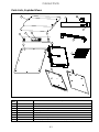
Cabinet Parts
4-1
Parts Lists, Exploded Views
Item
Part Number Description
1 108-1897 Top Cap
2 823-7636 Rear Fascia
3 807-4882 Circuit Breaker, 16 amp
4 807-5111 Time/Temperature switch
5 807-4911 Power switch
6 823-7513 Front fascia
7 807-5112 Master control overlay with ribbon cable
* 807-5156 Master display board (circuit board in master display assembly)
1
2
3
4
5
6
7
8
12
11
9
13
10
14

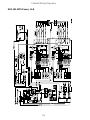
Cabinet Parts
4-2
Item
Part Number Description
8 807-5111 Time/Temperature switch
9 826-2781 Bezel, with boards, front with short ribbon cable
* 826-2782 Bezel with boards, rear, with long ribbon cable
10 108-1190 Base
11 807-4857 Heater plate/RTD
12 807-4860 Distribution board
13 108-1633 Side, left, vented
14 108-1632 Side right, not vented
* 230-7245 Bottom bezel facia, front or rear
Component Shelf
Item
Part Number Description
15 807-5150 Master control board
16 807-2665 Blower
17 807-4951 LON board, domestic
15
16
17
18
19
20
Page is loading ...
Page is loading ...
Page is loading ...
Page is loading ...
-
 1
1
-
 2
2
-
 3
3
-
 4
4
-
 5
5
-
 6
6
-
 7
7
-
 8
8
-
 9
9
-
 10
10
-
 11
11
-
 12
12
-
 13
13
-
 14
14
-
 15
15
-
 16
16
-
 17
17
-
 18
18
-
 19
19
-
 20
20
-
 21
21
-
 22
22
-
 23
23
-
 24
24


Ask a question and I''ll find the answer in the document
Finding information in a document is now easier with AI
Related papers
-
 Frymaster McDonald's UHC-HD Operating instructions
-
 Frymaster UHC-P User manual
-
 Frymaster UHC User manual
-
 Frymaster UHC-P Operating instructions
-
 Frymaster McDonald's UHC-HD Maintenance Manual
-
 Frymaster M3000 User manual
-
 Frymaster DECATHLON h50 User manual
-
 Frymaster BIELA14 User manual
-
 Frymaster 8196321 User manual
-
Frymaster filter User manual


Other documents
-
Henny Penny UHC 600 User guide
-
 Merco Products MercoMax Holding Cabinet (MHB) User manual
-
York 00497VIP User manual
-
ABB PGC5000 Series Service Instructions Manual
-
Daktronics Galaxy AF-3400 Series Display Manual
-
 Merco Products MercoMax™ Holding Cabinet (MHU) - User manual
-
 Merco Products Forced Air Holding Cabinet (MHCFA) User manual
-
Merco Products MercoMax Visual Holding Cabinet (MHC) - User manual
-
Gateway 9515 User manual
-


