Dell XPS PP19L Owner's manual
- Category
- Notebooks
- Type
- Owner's manual
This manual is also suitable for

Dell™ XPS M140 Service Manual
file:///C|/Users/santhosh_v.ASIA-PACIFIC/Desktop/Hawke/New%20folder/index.htm[2/21/2014 11:33:34 AM]
Dell™ XPS M140 Service Manual
Before You Begin
System Components
Internal Card With Bluetooth® Wireless
Technology
Hard Drive
Optical Drive
Memory Module and Modem
Hinge Cover
Keyboard
Coin-Cell Battery
Wireless Mini PCI Card
Display Assembly and Display Latch
Palm Rest
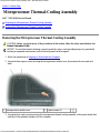
Microprocessor Thermal-Cooling
Assembly
Fan
Microprocessor Module
Speakers
System Board
BIOS Updates
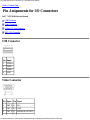
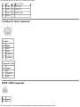
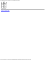
Pin Assignments for I/O Connectors
Notes, Notices, and Cautions
NOTE: A NOTE indicates important information that helps you make better use of your computer.
NOTICE: A NOTICE indicates either potential damage to hardware or loss of data and tells you how to avoid
the problem.
CAUTION: A CAUTION indicates a potential for property damage, personal injury, or death.
Information in this document is subject to change without notice.
© 2005 Dell Inc. All rights reserved.
Reproduction in any manner whatsoever without the written permission of Dell Inc. is strictly forbidden.
Trademarks used in this text: Dell, the DELL logo, and Inspiron are trademarks of Dell Inc.; Intel is a registered
trademark of Intel Corporation; Microsoft and Windows are registered trademarks of Microsoft Corporation; Bluetooth
is a trademark owned by Bluetooth SIG, Inc. and is used by Dell Inc. under license.
Other trademarks and trade names may be used in this document to refer to either the entities claiming the marks and
names or their products. Dell Inc. disclaims any proprietary interest in trademarks and trade names other than its own.
Model PP19L
October 2005 Rev. A00

Before You Begin: Dell XPS M170 Service Manual
file:///C|/Users/santhosh_v.ASIA-PACIFIC/Desktop/Hawke/New%20folder/begin0.htm[2/21/2014 11:33:36 AM]
Back to Contents Page
Before You Begin
Dell™ XPS M140 Service Manual
Preparing to Work Inside the Computer
Recommended Tools
Computer Orientation
Screw Identification
Preparing to Work Inside the Computer
CAUTION: Before you perform any of the procedures in this section, follow the safety instructions in the
Product Information Guide.
NOTICE: Only a certified service technician should perform repairs on your computer. Damage due to servicing
that is not authorized by Dell is not covered by your warranty.
NOTICE: To avoid electrostatic discharge, ground yourself by using a wrist grounding strap or by periodically
touching an unpainted metal surface (such as the back panel) on the computer.
NOTICE: Handle components and cards with care. Do not touch the components or contacts on a card. Instead,
hold a card by its edges or by its metal mounting bracket. Hold a component such as a microprocessor by its
edges, not by its pins.
NOTICE: When disconnecting a cable, pull on the cable's connector or on its strain-relief loop, not on the cable
itself. Some cables have connectors with locking tabs; before disconnecting this type of cable, press inward on
the locking tabs to release the connector. When connecting or disconnecting a cable, ensure that the connectors
are correctly oriented and aligned to avoid damage to the connector and/or the connector's pins.
NOTICE: To avoid damaging the computer, always perform the following steps before you begin working
inside the computer.
1. Ensure that the work surface is flat and clean to prevent scratching the computer cover.
2. Save any work in progress and exit all open programs.
3. Turn off the computer and all attached devices.
NOTE: Ensure that the computer is off and not in a power management mode. If you cannot shut down the
computer using the operating system, press and hold the power button for 4 seconds.
4. Disconnect the computer from the electrical outlet.

Before You Begin: Dell XPS M170 Service Manual
file:///C|/Users/santhosh_v.ASIA-PACIFIC/Desktop/Hawke/New%20folder/begin0.htm[2/21/2014 11:33:36 AM]
NOTICE: To avoid damaging the system board, wait 10 to 20 seconds before disconnecting any attached
devices.
5. Disconnect all attached devices.
6. Disconnect all external cables from the computer.
7. Close the display and turn the computer upside down on a flat work surface.
NOTICE: To avoid damaging the system board, you must remove the main battery before servicing the
computer.
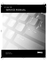
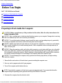
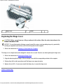
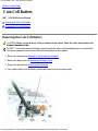
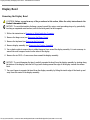
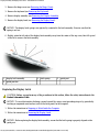
8. Slide and hold the battery bay latch release on the bottom of the computer, then pull the battery out of the
battery bay.
1 battery 2 battery bay latch release
Recommended Tools
The procedures in this document will require one or more of the following tools:
Small flat-blade screwdriver
Phillips screwdriver
Small plastic scribe
Flash BIOS update (see the Dell support website at support.dell.com)

Before You Begin: Dell XPS M170 Service Manual
file:///C|/Users/santhosh_v.ASIA-PACIFIC/Desktop/Hawke/New%20folder/begin0.htm[2/21/2014 11:33:36 AM]
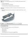
Computer Orientation
1 front 2 left 3 back
4 right
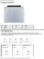
Screw Identification
The following chart provides the number of screws used to secure the various system components and their
corresponding sizes. When removing and replacing components, print the screw identification chart as a placemat to
lay out and keep track of the screws.
Optical Drive:
(1 each – optional)
Modem:
(1 each)
Bluetooth Module:
(1 each)

Before You Begin: Dell XPS M170 Service Manual
file:///C|/Users/santhosh_v.ASIA-PACIFIC/Desktop/Hawke/New%20folder/begin0.htm[2/21/2014 11:33:36 AM]
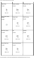
Hinge Cover:
(2 each)
Display Assembly:
(4 each)
Display Bezel (screw):
(6 each)
Display Bezel (rubber
bumper):
(6 each)
Display Panel:
(6 each)
Palm Rest (top):
(4 each)
Palm Rest (bottom):
(11 each)
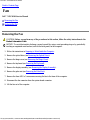
Fan:
(3 each)
Speakers:
(3 total)
System Board (top):
(1 each)
System Board (bottom):
(2 each)


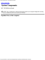
System Components: Dell™ XPS M140 Service Manual
file:///C|/Users/santhosh_v.ASIA-PACIFIC/Desktop/Hawke/New%20folder/system0.htm[2/21/2014 11:33:38 AM]
Back to Contents Page
System Components
Dell™ XPS M140 Service Manual
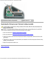
NOTICE: Only a certified service technician should perform repairs on your computer. Damage due to servicing
that is not authorized by Dell is not covered by your warranty.
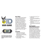
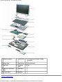
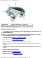
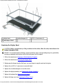
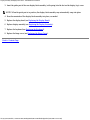
Exploded View of the Computer

System Components: Dell™ XPS M140 Service Manual
file:///C|/Users/santhosh_v.ASIA-PACIFIC/Desktop/Hawke/New%20folder/system0.htm[2/21/2014 11:33:38 AM]
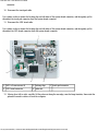
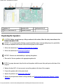
1 display assembly 6 optical drive 11 microprocessor thermal-cooling
assembly
2 hinge cover 7 main battery 12 microprocessor
3 keyboard 8 computer
base
13 fan
4 palm rest (with touch
pad)
9 hard drive
5 system board 10 speakers
Back to Contents Page

System Components: Dell™ XPS M140 Service Manual
file:///C|/Users/santhosh_v.ASIA-PACIFIC/Desktop/Hawke/New%20folder/system0.htm[2/21/2014 11:33:38 AM]

Internal Card With Bluetooth® Wireless Technology: Dell™ XPS M140 Service Manual
file:///C|/Users/santhosh_v.ASIA-PACIFIC/Desktop/Hawke/New%20folder/blue0.htm[2/21/2014 11:33:39 AM]
Back to Contents Page
Internal Card With Bluetooth® Wireless Technology
Dell™ XPS M140 Service Manual
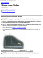
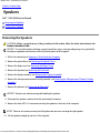
Removing the Bluetooth Module
Replacing the Bluetooth Module
NOTE: If you ordered the optional internal card with Bluetooth wireless technology at the same time that you
ordered your computer, the card is already installed.
Removing the Bluetooth Module
CAUTION: Before you perform any of the procedures in this section, follow the safety instructions in the
Product Information Guide.
NOTICE: To avoid electrostatic discharge, ground yourself by using a wrist grounding strap or by periodically
touching an unpainted metal surface (such as the back panel) on the computer.
1. Follow the instructions in Preparing to Work Inside the Computer.
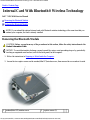
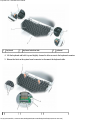
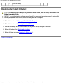
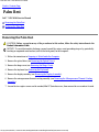
2. Loosen the two captive screws on the modem/Mini PCI/wireless cover, then remove the cover and set it aside.
1 modem/Mini PCI/wireless cover 2 captive screws (2)

Internal Card With Bluetooth® Wireless Technology: Dell™ XPS M140 Service Manual
file:///C|/Users/santhosh_v.ASIA-PACIFIC/Desktop/Hawke/New%20folder/blue0.htm[2/21/2014 11:33:39 AM]
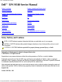
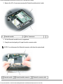
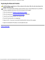
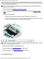
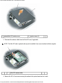
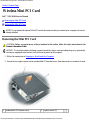
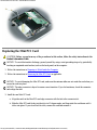
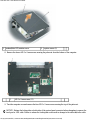
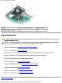
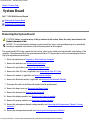
3. Remove the M2 x 3-mm screw securing the Bluetooth module and set it aside.
1 Bluetooth module 2 M2 x 3-mm screw
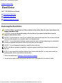
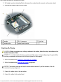
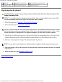
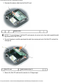
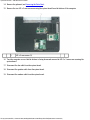
4. Lift the Bluetooth module from its compartment.
5. Grasp the card and gently pull it apart from the connector cable.
NOTE: Do not disconnect the Bluetooth connector cable from the system board.
1 Bluetooth module 2 Bluetooth module connector 3 Bluetooth connector cable

Internal Card With Bluetooth® Wireless Technology: Dell™ XPS M140 Service Manual
file:///C|/Users/santhosh_v.ASIA-PACIFIC/Desktop/Hawke/New%20folder/blue0.htm[2/21/2014 11:33:39 AM]
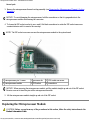
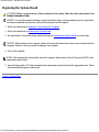
Replacing the Bluetooth Module
CAUTION: Before you perform any of the procedures in this section, follow the safety instructions in the
Product Information Guide.
NOTICE: To avoid electrostatic discharge, ground yourself by using a wrist grounding strap or by periodically
touching an unpainted metal surface (such as the back panel) on the computer.
1. Follow the instructions in Preparing to Work Inside the Computer.
2. Follow the instructions in Removing the Bluetooth Module, as applicable.
3. Connect the new Bluetooth module to the connector cable.
4. Place the Bluetooth module in its compartment.
5. Replace the M2 x 3-mm screw to secure the Bluetooth module to the base of the computer.
6. Replace the modem/Mini PCI/wireless cover and tighten the screws.
Back to Contents Page

Hard Drive: Dell™ XPS M140 Service Manual
file:///C|/Users/santhosh_v.ASIA-PACIFIC/Desktop/Hawke/New%20folder/hdd0.htm[2/21/2014 11:33:41 AM]
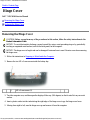
Back to Contents Page
Hard Drive
Dell™ XPS M140 Service Manual
Removing the Hard Drive
Replacing the Hard Drive
Returning a Hard Drive to Dell
Removing the Hard Drive
CAUTION: Before you perform any of the procedures in this section, follow the safety instructions in the
Product Information Guide.
CAUTION: Do not touch the metal housing of the hard drive if you remove the hard drive from the
computer while the drive is hot.
NOTICE: To prevent data loss, turn off your computer before removing the hard drive. Do not remove the hard
drive while the computer is on, in standby mode, or in hibernate mode.
NOTICE: To avoid electrostatic discharge, ground yourself by using a wrist grounding strap or by periodically
touching an unpainted metal surface (such as the back panel) on the computer.
NOTICE: To avoid damaging the hard drive, handle the drive with care.
NOTE: Dell does not guarantee compatibility or provide support for hard drives obtained from sources other
than Dell.
NOTE: If you are installing a hard drive obtained from a source other than Dell, you may need to install an
operating system, drivers, and utilities on the new drive.
1. Follow the instructions in Preparing to Work Inside the Computer.
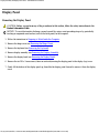
2. Loosen the two captive screws securing the hard drive cover, then remove the cover and set it aside.

Hard Drive: Dell™ XPS M140 Service Manual
file:///C|/Users/santhosh_v.ASIA-PACIFIC/Desktop/Hawke/New%20folder/hdd0.htm[2/21/2014 11:33:41 AM]
1 hard drive cover 2 captive screws (2)
NOTICE: When the hard drive is not in the computer, store it in protective, antistatic packaging. See "Protecting
Against Electrostatic Discharge" in the Product Information Guide.
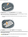
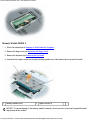
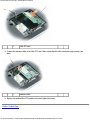
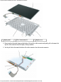
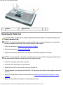
3. Use the pull-tab to slide the hard drive toward the screw holes, then lift the drive straight up to remove it from
the computer.
1 hard drive 2 pull tab
Replacing the Hard Drive
CAUTION: Before you perform any of the procedures in this section, follow the safety instructions in the
Product Information Guide.

Hard Drive: Dell™ XPS M140 Service Manual
file:///C|/Users/santhosh_v.ASIA-PACIFIC/Desktop/Hawke/New%20folder/hdd0.htm[2/21/2014 11:33:41 AM]
NOTICE: To avoid electrostatic discharge, ground yourself by using a wrist grounding strap or by periodically
touching an unpainted metal surface (such as the back panel) on the computer.
1. Follow the instructions in Preparing to Work Inside the Computer.
2. Follow the instructions in Removing the Hard Drive.
NOTICE: Use firm and even pressure when sliding the hard drive into place. Excessive force may result in
damage to the connector.
3. Place the new hard drive into the bay, then slide it away from the screw holes into the connector until it is fully
seated.
4. Replace the hard drive cover and tighten the screws.
5. Install the operating system for your computer, if necessary (see "Restoring Your Operating System" in your
Owner's Manual).
6. Install the drivers and utilities for your computer, if necessary (see "Reinstalling Drivers and Utilities" in your
Owner's Manual).
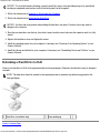
Returning a Hard Drive to Dell
Return your hard drive to Dell in the replacement drive's foam packaging. Otherwise, the hard drive may be damaged
in transit.
NOTE: The hard drive should be inserted in the replacement drive's antistatic bag before being placed in the
foam packaging.
1 hard drive (in antistatic bag) 2 foam packaging
Back to Contents Page

Hard Drive: Dell™ XPS M140 Service Manual
file:///C|/Users/santhosh_v.ASIA-PACIFIC/Desktop/Hawke/New%20folder/hdd0.htm[2/21/2014 11:33:41 AM]

Optical Drive: Dell™ XPS M140 Service Manual
file:///C|/Users/santhosh_v.ASIA-PACIFIC/Desktop/Hawke/New%20folder/opticald.htm[2/21/2014 11:33:43 AM]
Back to Contents Page
Optical Drive
Dell™ XPS M140 Service Manual
About the Device Security Screw
Removing the Optical Drive
Replacing the Optical Drive
About the Device Security Screw
NOTE: You do not need to install the device security screw unless you want to prevent the optical drive from
being easily removed.
Your Dell™ computer ships with a CD/DVD drive installed in the optical drive bay along with an M2.5 x 8-mm
device security screw. If the security screw is not already installed, it will be packaged separately. When you insert a
drive into the bay, you can install the device security screw to prevent the drive from being easily removed.
Removing the Optical Drive
CAUTION: Before you perform any of the procedures in this section, follow the safety instructions in the
Product Information Guide.
NOTICE: To prevent damage to optical drives and other devices, store them in a safe, dry place when they are
not installed in the computer. Avoid pressing down on them or placing heavy objects on top of them.
1. Follow the instructions in Preparing to Work Inside the Computer.
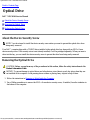
2. Use a Phillips screwdriver to remove the M2.5 x 8-mm device security screw, if installed, from the indention in
the bottom of the computer.

Optical Drive: Dell™ XPS M140 Service Manual
file:///C|/Users/santhosh_v.ASIA-PACIFIC/Desktop/Hawke/New%20folder/opticald.htm[2/21/2014 11:33:43 AM]
1 indention 2 M2.5 x 8-mm device security screw (optional)
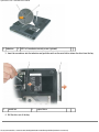
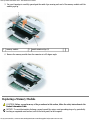
3. Insert the screwdriver into the indention and push the notch on the metal tab to release the drive from the bay.
1 metal tab 2 optical drive
4. Pull the drive out of the bay.

Optical Drive: Dell™ XPS M140 Service Manual
file:///C|/Users/santhosh_v.ASIA-PACIFIC/Desktop/Hawke/New%20folder/opticald.htm[2/21/2014 11:33:43 AM]
Replacing the Optical Drive
CAUTION: Before you perform any of the procedures in this section, follow the safety instructions in the
Product Information Guide.
1. Follow the instructions in Preparing to Work Inside the Computer.
2. Follow the instructions in Removing the Optical Drive.
3. Slide the new drive into the bay until it snaps securely into place.
4. Replace the M2.5 x 8-mm device security screw (optional).
Back to Contents Page

Memory Module and Modem: Dell™ XPS M140 Service Manual
file:///C|/Users/santhosh_v.ASIA-PACIFIC/Desktop/Hawke/New%20folder/upgrades.htm[2/21/2014 11:33:45 AM]
Back to Contents Page
Memory Module and Modem
Dell™ XPS M140 Service Manual
Removing a Memory Module
Replacing a Memory Module
Modem
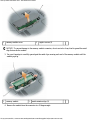
Your Dell computer comes equipped with two memory slots/connectors labeled DIMM A and DIMM B. DIMM A
(located under the keyboard) holds the primary memory module as configured from the factory. DIMM B (located on
the bottom of the computer) holds any additional memory you may have ordered. If you did not order additional
memory, DIMM B will be empty.
Generally, if you are adding memory, you will install a memory module in DIMM B only. If you are upgrading the
memory, you may need to install memory modules in DIMM A and DIMM B, depending on the extent of the upgrade.
NOTE: Memory modules purchased from Dell™ are covered under your computer warranty.
Removing a Memory Module
CAUTION: Before you perform any of the procedures in this section, follow the safety instructions in the
Product Information Guide.
NOTICE: To avoid electrostatic discharge, ground yourself by using a wrist grounding strap or by periodically
touching an unpainted metal surface (such as the back panel) on the computer.
Memory Module DIMM B
1. Follow the instructions in Preparing to Work Inside the Computer.
2. Loosen the two captive screws securing the memory module cover, then remove the cover and set it aside.
Page is loading ...
Page is loading ...
Page is loading ...
Page is loading ...
Page is loading ...
Page is loading ...
Page is loading ...
Page is loading ...
Page is loading ...
Page is loading ...
Page is loading ...
Page is loading ...
Page is loading ...
Page is loading ...
Page is loading ...
Page is loading ...
Page is loading ...
Page is loading ...
Page is loading ...
Page is loading ...
Page is loading ...
Page is loading ...
Page is loading ...
Page is loading ...
Page is loading ...
Page is loading ...
Page is loading ...
Page is loading ...
Page is loading ...
Page is loading ...
Page is loading ...
Page is loading ...
Page is loading ...
Page is loading ...
Page is loading ...
Page is loading ...
Page is loading ...
Page is loading ...
Page is loading ...
Page is loading ...
Page is loading ...
Page is loading ...
Page is loading ...
Page is loading ...
Page is loading ...
Page is loading ...
Page is loading ...
Page is loading ...
Page is loading ...
Page is loading ...
Page is loading ...
Page is loading ...
-
 1
1
-
 2
2
-
 3
3
-
 4
4
-
 5
5
-
 6
6
-
 7
7
-
 8
8
-
 9
9
-
 10
10
-
 11
11
-
 12
12
-
 13
13
-
 14
14
-
 15
15
-
 16
16
-
 17
17
-
 18
18
-
 19
19
-
 20
20
-
 21
21
-
 22
22
-
 23
23
-
 24
24
-
 25
25
-
 26
26
-
 27
27
-
 28
28
-
 29
29
-
 30
30
-
 31
31
-
 32
32
-
 33
33
-
 34
34
-
 35
35
-
 36
36
-
 37
37
-
 38
38
-
 39
39
-
 40
40
-
 41
41
-
 42
42
-
 43
43
-
 44
44
-
 45
45
-
 46
46
-
 47
47
-
 48
48
-
 49
49
-
 50
50
-
 51
51
-
 52
52
-
 53
53
-
 54
54
-
 55
55
-
 56
56
-
 57
57
-
 58
58
-
 59
59
-
 60
60
-
 61
61
-
 62
62
-
 63
63
-
 64
64
-
 65
65
-
 66
66
-
 67
67
-
 68
68
-
 69
69
-
 70
70
-
 71
71
-
 72
72


Dell XPS PP19L Owner's manual
- Category
- Notebooks
- Type
- Owner's manual
- This manual is also suitable for
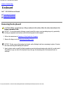
Ask a question and I''ll find the answer in the document
Finding information in a document is now easier with AI