Page is loading ...

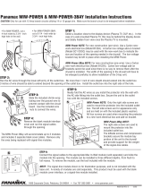
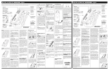
STEP 1:
Select a location close to the equipment. In the case of a at panel
display, the recommended location is one that is behind the device
and hidden from view once the Plasma TV is mounted. Cut a 4”
wide by 3 3/4” high hole in the wall for the mounting bracket.
STEP 2:
Run the signal line(s) through the mounting bracket.
Install the mounting bracket in the hole.
STEP 3:
Remove the rubber plug from one of the Signal Bay Pass-
Throughs. Cut a hole in the rubber plug so that it ts snugly
around the signal line. Pass the signal line through the Signal
Bay Pass-Throughs, place the rubber plug over the signal line,
and put the rubber plug back in place.
STEP 4:
Install the Max In-Wall Dual Signal Bay into the mounting bracket
and secure with the included screws.
Signal Protection Module Usage:
Panamax In-Wall signal protection modules (sold separately),
while not necessary for surge protection in the Max In-Wall Dual
Signal Bay, may be used to provide a clean looking interface for
the signal lines. When used in the proper manner the modules
also provide total protection to the connected equipment.
NOTE:
In order for the signal protection modules to protect against surg-
es, the ground wire on the Max In-Wall Signal Bay may be con-
nected to the ground wire on the Max In-Wall Power-PRO that is
installed nearby (less than 1 foot away). Simply connect it with the
same wire nut that is used to connect the Max In-Wall Power-PRO
to the building wire.
1
PANAMAX MAX IN-WALL DUAL SIGNAL BAY INSTALLATION INSTRUCTIONS
INS00811 REV A 03/07
STEP 5:
Repeat steps 1-4 for the Dual Signal Bay located at the source
components.

2
MAX IN-WALL DUAL SIGNAL BAY SPECIFICATIONS
Summary of Features
Accommodates two blank module inserts with pass-through plugs (included) or two InWall signal
protection modules (sold separately).
Full metal housing
Enlarged faceplates (4.5” x 4.5”) to accomodate oversize wall cutouts.
Fits into many two-gang outlet brackets (old-work, low-voltage, Caddy-brand outlet bracket
(model MPAL2) included.
14 AWG, solid wire connection for bonding / grounding to In-Wall AC units.
Provides an elegant, convenient solution for connecting signal lines from the source device to the
display device when running cables within the building walls.
Specications are subject to changes due to product upgrades and improvements.
•
•
•
•
•
•
CONTENTS
CONTACTING PANAMAX
Panamax
1690 Corporate Circle
Petaluma, CA 94954
Phone - 707-283-5900 or 800-472-5555
Fax - 707-283-5901
Web - www.panamax.com
Customer Relations
7:30 AM – 4:30 PM, M-F Pacic Time
Email - [email protected]
One MAX In-Wall
signal bay enclosure
(4) Mounting Screws
(1) Mounting Bracket
Included Installation Accessories:
/
