Page is loading ...

*6881094C00*
68P81094C00-B
EX500
EX600
••
XLS
Motorola, The Sylized M logo, and Intelligence Everywhere are trademarks of Motorola, Inc.
All other product or service names are the property of their respective owners.
© 2002 Motorola, Inc. All rights reserved. Printed in U.S.A.
EX500
™
EX600
™
EX600
••
XLS
™
Expert Series
Two-Way Radio Basic Service Manual

Product Software License Agreement
THIS LICENSE AGREEMENT BETWEEN YOU, THE USER, AND MOTOROLA, APPLIES TO THE SOFT-
WARE EMBEDDED IN OR DELIVERED WITH THE ACCOMPANYING MOTOROLA PRODUCT (“SOFT-
WARE”), AND IS APPLICABLE UNLESS A SIGNED LICENSE AGREEMENT COVERING ITS SUBJECT
MATTER HAS BEEN EXECUTED BETWEEN YOU AND MOTOROLA. BY USING THE PRODUCT, YOU
ACKNOWLEDGE THAT THIS AGREEMENT HAS BEEN READ AND UNDERSTOOD AND THAT YOU
AGREE TO BE BOUND BY ITS TERMS AND CONDITIONS. IF YOU DO NOT AGREE, YOU ARE NOT
LICENSED TO USE THE PRODUCT, AND IF YOU ARE THE PURCHASER OF THE PRODUCT, YOU
SHOULD IMMEDIATELY RETURN THE PRODUCT IN ITS ENTIRETY TO ITS PLACE OF PURCHASE FOR
A REFUND.
Motorola grants to You a non-exclusive license to use the SOFTWARE in the manner described in the docu-
mentation associated with the product. Motorola retains ownership of the SOFTWARE including all patent,
copyrights, and other intellectual property rights. You may transfer this license to use the SOFTWARE as long
as the transferee agrees to be bound by the terms of this Agreement.
You agree not to reverse engineer or create derivative works of the SOFTWARE; not to transmit the SOFT-
WARE electronically; not to modify, configure, or use the SOFTWARE in any manner not authorized by
MOTOROLA; and, except as an integral part of the product, not to rent, lease, or convey the SOFTWARE.
MOTOROLA SHALL NOT BE LIABLE FOR INCIDENTAL OR CONSEQUENTIAL DAMAGES ARISING
FROM THE USE OF THIS SOFTWARE.
With respect to the U.S. Government, if acquired under FAR policy (52.227-19), the SOFTWARE is provided
with Restricted Rights, and if acquired under DFARS policy (227.7202), then the SOFTWARE is provided only
with the commercial rights of this Agreement.
This license is effective until terminated. It will terminate immediately and automatically if You fail to comply
with any term of this Agreement.
You agree that this is the complete and exclusive statement of the agreement between You and Motorola and
that any modification of these terms shall be made only by mutual agreement and evidenced by written
amendment signed by both parties. This Agreement shall be governed and interpreted by the laws of the
State of Illinois, United States of America.
Computer Software Copyrights
This manual may not be reproduced, in whole or in part, in any form whatsoever, without the express written per-
mission of Motorola, Inc.
The Motorola products described in this manual contain one or more computer programs. These computer
programs are protected by copyright law and international treaties. Unauthorized reproduction or distribution
of these programs, or any part thereof, may result in severe civil and criminal penalties, and will be prosecuted
to the maximum extent possible under the law. U.S. and international patents pending.
This product is covered by one or more issued U.S. Patents. Other Patent applications pending.

i
Table of Contents
Product Safety and RF Exposure Compliance........................v
Chapter 1 Introduction
1.1 Scope of Manual....................................................................................................1-1
1.2 Warranty and Service Support...............................................................................1-1
1.2.1 Warranty Period and Return Instructions............................................................ 1-1
1.2.2 After Warranty Period..........................................................................................1-1
1.2.3 Piece Parts Availability........................................................................................1-2
1.2.4 Technical Support ...............................................................................................1-3
1.3 Radio Model Information........................................................................................1-4
Chapter 2 Intrinsically Safe Radio Information
2.1 FMRC Approved Equipment..................................................................................2-1
2.2 Repair of FMRC Approved Products......................................................................2-2
2.2.1 Repair..................................................................................................................2-2
2.2.2 Relabeling ...........................................................................................................2-2
2.2.3 Do Not Substitute Options or Accessories..........................................................2-3
Chapter 3 Maintenance
3.1 Introduction ............................................................................................................3-1
3.2 Preventive Maintenance.........................................................................................3-1
3.2.1 Inspection............................................................................................................3-1
3.2.2 Cleaning Procedures...........................................................................................3-1
3.3 Safe Handling of CMOS and LDMOS Devices......................................................3-2
3.4 Repair Procedures and Techniques — General....................................................3-3
3.5 Disassembling and Reassembling the Radio — General......................................3-4
3.6 EX500 Radio Disassembly — Detailed..................................................................3-5
3.6.1 Front Cover from Chassis Disassembly..............................................................3-5
3.6.2 Chassis Assembly Disassembly.......................................................................... 3-7
3.6.3 Speaker, Microphone, and Universal Connector Flex Disassembly ...................3-8
3.6.4 Controller Board Disassembly.............................................................................3-9
3.6.5 Control Top Disassembly ....................................................................................3-9
3.7 EX500 Radio Reassembly — Detailed ..................................................................3-9
3.7.1 Control Top Reassembly.....................................................................................3-9

ii
3.7.2 Speaker, Microphone, and Universal Connector Flex Reassembly.................. 3-10
3.7.3 Chassis Assembly Reassembly........................................................................ 3-10
3.7.4 Chassis and Front Cover Reassembly.............................................................. 3-10
3.8 EX600 / EX600•XLS Radio Disassembly and Reassembly — General...............3-11
3.9 EX600 / EX600•XLS Radio Disassembly — Detailed ..........................................3-12
3.9.1 Front Cover from Chassis Disassembly............................................................ 3-12
3.9.2 Chassis Assembly Disassembly ....................................................................... 3-14
3.9.3 Speaker, Microphone, and Universal Connector Flex Disassembly................. 3-15
3.9.4 Controller Board, Display Module and Keypad Disassembly............................ 3-17
3.9.5 Control Top Disassembly.................................................................................. 3-18
3.10 EX600 / EX600•XLS Radio Reassembly — Detailed...........................................3-18
3.10.1 Control Top Reassembly................................................................................... 3-18
3.10.2 Speaker, Microphone, and Universal Connector Flex Reassembly.................. 3-18
3.10.3 Chassis Assembly Reassembly........................................................................ 3-18
3.10.4 Chassis and Front Cover Reassembly.............................................................. 3-19
3.11 Mechanical Views and Parts Lists........................................................................3-20
3.11.1 EX500 Exploded View and Parts List................................................................ 3-20
3.11.2 EX600 / EX600•XLS Exploded View and Parts List.......................................... 3-22
3.12 Service Aids..........................................................................................................3-24
3.13 Test Equipment ....................................................................................................3-25
3.14 Programming/Test Cable......................................................................................3-26
Chapter 4 Transceiver Performance Testing
4.1 Introduction.............................................................................................................4-1
4.2 Setup......................................................................................................................4-1
4.3 Test Mode...............................................................................................................4-2
4.3.1 RF Test Mode ..................................................................................................... 4-2
Chapter 5 Radio Tuning and Programming
5.1 Introduction.............................................................................................................5-1
5.2 Radio Tuning Setup................................................................................................5-1
5.3 CPS Programming Setup.......................................................................................5-2
5.4 Cloning Information ................................................................................................5-3
Chapter 6 Power Up Self-Test
6.1 Error Codes............................................................................................................6-1

iii
Chapter 7 Accessories
7.1 Antennas................................................................................................................7-1
7.2 Carry Cases for EX500 / EX600 / EX600•XLS ......................................................7-1
7.3 Chargers ...............................................................................................................7-2
7.4 Batteries ................................................................................................................7-2
7.5 Audio Accessories..................................................................................................7-2
7.6 Microphones...........................................................................................................7-2
7.7 Ear Microphone System.........................................................................................7-2
7.8 Manuals .................................................................................................................7-3
Chapter 8 Model Chart and Test Specifications
8.1 136-174 MHz..........................................................................................................8-1
8.2 403-470 MHz..........................................................................................................8-2
8.3 450-512 MHz..........................................................................................................8-3
8.4 Specifications.........................................................................................................8-4
Glossary of Terms

iv

v
PRODUCT SAFETY AND RF EXPOSURE COMPLIANCE
ATTENTION!
This radio is restricted to occupational use only to satisfy FCC RF energy exposure requirements.
Before using this product, read the RF energy awareness information and operating instructions in the
Product Safety and RF Exposure booklet enclosed with your radio (Motorola Publication part number
68P81095C98) to ensure compliance with RF energy exposure limits.
For a list of Motorola-approved antennas, batteries, and other accessories, visit the following web site which
lists approved accessories: http://www.motorola.com/cgiss/index.shtml.
Before using this product, read the operating instructions for safe usage contained in the
Product Safety and RF Exposure booklet enclosed with your radio.
!
C a u t i o n

vi Safety and General Information

1-1
Chapter 1
Introduction
1.1 Scope of Manual
This manual is intended for use by service technicians familiar with similar types of equipment. It
contains service information required for the equipment described in this document and is current as
of the printing date. Changes which occur after the printing date will be incorporated in a complete
Manual Revision or alternatively as additions.
1.2 Warranty and Service Support
Motorola offers support which includes: full exchange and/or repair of the product during the warranty
period; and service/repair or spare parts support out of warranty. Any “return for exchange” or “return
for repair” to an authorized Motorola Dealer must be accompanied by a Warranty Claim Form.
Warranty Claim Forms are available from Authorized Motorola Dealers.
1.2.1 Warranty Period and Return Instructions
The terms and conditions of warranty are defined fully in the Motorola Dealer, Distributor or Reseller
contract. These conditions may change from time to time, and the following subsections are for
guidance purposes only.
In instances where the product is covered under a “return for replacement” or “return for repair”
warranty, a check of the product should be performed prior to shipping the unit back to Motorola. This
is to ensure that the product has been correctly programmed or has not been subjected to damage
outside the terms of the warranty.
Prior to shipping any radio back to the appropriate Motorola warranty depot, please contact Customer
Resources. (See section 1.2.4 on page 1-3 of this chapter.) All returns must be accompanied by a
Warranty Claim Form available from your Customer Resources representative. Products should be
shipped back in the original packaging, or correctly packaged to ensure that no damage occurs in
transit.
1.2.2 After Warranty Period
After the Warranty period, Motorola continues to support its products in two ways:
1. Motorola's Radio Parts and Service Group offers repair service to users and dealers at competi-
tive prices.
2. The Motorola Accessories and Aftermarket Division (AAD) supplies individual parts and modules
that can be purchased by dealers who are capable of performing fault analysis and repair.
NOTE
Before operating or testing these units, please read the Safety Information Section at the
beginning of this manual.

1-2 Warranty and Service Support
1.2.3 Piece Parts Availability
Some replacement parts, spare parts, and/or product information can be ordered directly.
Parts Order Entry:
7:00 A.M. to 7:00 P.M. (Central Standard Time)
Monday through Friday (Chicago, U.S.A.)
To Order Parts:
1-800-422-4210, or 847-538-8023
1-800-826-1913, or 410-712-4907 (U.S. Federal Government)
TELEX: 280127
FAX: 1-847-538-8198
FAX: 1-410-712-4991 (U.S. Federal Government)
(U.S.A.) after hours or weekends:
1-800-925-4357
Motorola Parts
Accessories and Aftermarket Division
(United States and Canada)
Attention: Order Processing
2200 Galvin Dr.
Elgin, IL 60123
Parts Identification
1-800-422-4210 Menu 3
If... It Means That...
A complete Motorola part number is assigned to
the part, and it is not identified as Depot ONLY
The part is available from AAD.
No part number is assigned The part is not normally available from Motorola.
The part number is appended with an asterisk, The part is serviceable by a Motorola Depot
only.
A parts list is not included Generally, no user-serviceable parts are
available for that kit or assembly.

Warranty and Service Support 1-3
1.2.4 Technical Support
Technical support is available to assist the dealer/distributor in resolving any malfunction which may
be encountered. Initial contact should be by telephone to Customer Resources wherever possible.
When contacting Motorola Technical Support, keep the product model number and the unit’s serial
number handy.
For service, contact one of the following Depots. Please call and confirm your return before sending
the unit to the depot for service.
Motorola Radio Support Center
3761 South Central Avenue
Rockford, IL 61102-4294
1-800-227-6772
1-815-489-1000
Motorola Toronto Service Center
400 Matheson Blvd. W
Mississauga, Ontario, Canada L5R 3M1
1-800-543-3222
1-416-756-5841
1-888-331-9872 (Fax)
Motorola U.S. Federal Government Depot
4395 Nicole Drive
Lanham, MD 20706
1-800-969-6680
1-301-731-6676

1-4 Radio Model Information
1.3 Radio Model Information
The model number and serial number are located on a label attached to the back of your radio. You
can determine the RF output power, frequency band, protocols, and physical packages. The example
below shows one portable radio model number and its specific characteristics.
Table 1-1: Radio Model Number (Example: AAH38KDC9AA3)
Type of
Unit
Model
Series
Freq.
Band
Power
Level
Physical
Packages
Channel
Spacing
Protocol
Feature
Level
Model
Revision
Model
Package
AA H 38 K
VHF
(136-
174MHz)
D
4-5W
C
EX500
No display
9
Program-
mable
AA
Conven-
tional
3
EX500
AN
R
UHF1
(403-
470MHz)
H
EX600 /
EX600•XLS
Full Keypad
with display
DU
LTR
6
EX600 /
EX600•XLS
S
UHF2
(450-512
MHz)
AA = Motorola Internal Use
Portable

2-1
Chapter 2
Intrinsically Safe Radio Information
2.1 FMRC Approved Equipment
Anyone intending to use a radio in a location where hazardous concentrations of flammable material
exist (hazardous atmosphere) is advised to become familiar with the subject of intrinsic safety and
with the National Electric Code NFPA 70 (National Fire Protection Association) Article 500 (hazardous
[classified] locations).
An Approval Guide, issued by Factory Mutual Research Corporation (FMRC), lists manufacturers and
the products approved by FMRC for use in such locations. FMRC has also issued a voluntary
approval standard for repair service (“Class Number 3605”).
FMRC Approval labels are attached to the radio to identify the unit as being FM Approved for
specified hazardous atmospheres. This label specifies the hazardous Class/Division/Group along
with the part number of the battery that must be used. Depending on the design of the portable unit,
this FM label can be found on the back or the bottom of the radio housing. The FM Approval mark is
shown below:
Radios must ship from the Motorola manufacturing facility with the hazardous atmosphere capability
and FM Approval labeling. Radios will not be “upgraded” to this capability and labeled in the field.
WARNING: Do not operate radio communications equipment in a hazardous atmosphere
unless it is a type especially qualified for such use (e.g., FMRC Approved). An explosion
or fire may result.
WARNING: Do not operate an FMRC Approved Product in a hazardous atmosphere if it
has been physically damaged (e.g., cracked housing). An explosion or fire may result.
WARNING: Do not replace or charge batteries in a hazardous atmosphere. Contact spark-
ing may occur while installing or removing batteries and cause an explosion or fire.
WARNING: Do not replace or change accessories in a hazardous atmosphere. Contact
sparking may occur while installing or removing accessories and cause an explosion or
fire.
WARNING: Do not operate an FMRC Approved Product unit in a hazardous location with
the accessory contacts exposed. Keep the connector cover in place when accessories are
not used.
WARNING: Turn a radio off before removing or installing a battery or accessory.
WARNING: Do not disassemble an FMRC Approved Product unit in any way that exposes
the internal electrical circuits of the unit.
FM
APPROVED
!
W A R N I N G
!

2-2 Repair of FMRC Approved Products
A modification changes the unit’s hardware from its original design configuration. Modifications can
only be made by the original product manufacturer at one of its FMRC-audited manufacturing
facilities.
Unauthorized or incorrect modification of an FMRC Approved Product unit will negate the Approval
rating of the product.
2.2 Repair of FMRC Approved Products
REPAIRS FOR MOTOROLA PRODUCTS WITH FMRC APPROVAL ARE THE RESPONSIBILITY
OF THE USER.
You should not repair or relabel any Motorola- manufactured communication equipment bearing the
FMRC Approval label (“FMRC Approved Product”) unless you are familiar with the current FMRC
Approval standard for repairs and service (“Class Number 3605”).
You may want to consider using a repair facility that operates under 3605 repair service approval.
FMRC’s Approval Standard Class Number 3605 is subject to change at any time without notice to
you, so you may want to obtain a current copy of 3605 from FMRC. Per the December 1994
publication of 3605, some key definitions and service requirements are as follows:
2.2.1 Repair
A repair constitutes something done internally to the unit that would bring it back to its original
condition—Approved by FMRC. A repair should be done in an FMRC Approved facility.
Items not considered as repairs are those in which an action is performed on a unit which does not
require the outer casing of the unit to be opened in a manner which exposes the internal electrical
circuits of the unit. You do not have to be an FMRC Approved Repair Facility to perform these actions.
2.2.2 Relabeling
The repair facility shall have a method by which the replacement of FMRC Approval labels are
controlled to ensure that any relabeling is limited to units that were originally shipped from the
Manufacturer with an FM Approval label in place. FMRC Approval labels shall not be stocked by the
repair facility. An FMRC Approval label shall be ordered from the original manufacturer as needed to
repair a specific unit. Replacement labels may be obtained and applied by the repair facility providing
satisfactory evidence that the unit being relabeled was originally an FMRC Approved unit. Verification
may include, but is not limited to: a unit with a damaged Approval label, a unit with a defective housing
displaying an Approval label, or a customer invoice indicating the serial number of the unit and
purchase of an FMRC Approved model.
WARNING: Failure to use an FMRC Approved Product unit with an FMRC Approved battery
or FMRC Approved accessories specifically approved for that product may result in the
dangerously unsafe condition of an unapproved radio combination being used in a hazard-
ous location.
WARNING: Incorrect repair or relabeling of any FMRC Approved Product unit could
adversely affect the Approval rating of the unit.
WARNING: Use of a radio that is not intrinsically safe in a hazardous atmosphere could
result in serious injury or death.
!
W A R N I N G
!
!
W A R N I N G
!

Repair of FMRC Approved Products 2-3
2.2.3 Do Not Substitute Options or Accessories
The Motorola communications equipment certified by Factory Mutual is tested as a system and
consists of the FM Approved portable, FM Approved battery, and FM Approved accessories or
options, or both. This FM Approved portable and battery combination must be strictly observed. There
must be no substitution of items, even if the substitute has been previously Approved with a different
Motorola communications equipment unit. Approved configurations are listed in the FM Approval
Guide published by FMRC, or in the product FM Supplement. This FM Supplement is shipped from
the manufacturer with the FM Approved radio and battery combination. The Approval Guide, or the
Approval Standard Class Number 3605 document for repairs and service, can be ordered directly
from Factory Mutual Research Corporation located in Norwood, Massachusetts, USA.

2-4 Repair of FMRC Approved Products
Notes

3-1
Chapter 3
Maintenance
3.1 Introduction
This chapter provides details about the following:
• Preventive maintenance (inspection and cleaning)
• Safe handling of CMOS and LDMOS devices
• Disassembly and reassembly of the radio
• Repair procedures and techniques
3.2 Preventive Maintenance
The radios do not require a scheduled preventive maintenance program; however, periodic visual
inspection and cleaning is recommended.
3.2.1 Inspection
Check that the external surfaces of the radio are clean, and that all external controls and switches are
functional. It is not recommended to inspect the interior electronic circuitry.
3.2.2 Cleaning Procedures
The following procedures describe the recommended cleaning agents and the methods to be used
when cleaning the external and internal surfaces of the radio. External surfaces include the front
cover, housing assembly and battery case. These surfaces should be cleaned whenever a periodic
visual inspection reveals the presence of smudges, grease, and/or grime.
The only recommended agent for cleaning the external radio surfaces is a 0.5% solution of a mild
dishwashing detergent in water. The only factory recommended liquid for cleaning the printed circuit
boards and their components is isopropyl alcohol (70% by volume).
Cleaning External Plastic Surfaces
Apply the 0.5% detergent-water solution sparingly with a stiff, non-metallic, short-bristled brush to
work all loose dirt away from the radio. Use a soft, absorbent, lintless cloth or tissue to remove the
solution and dry the radio. Make sure that no water remains entrapped near the connectors, cracks, or
crevices.
NOTE
Internal surfaces should be cleaned only when the radio is disassembled for service or
repair.
CAUTION: The effects of certain chemicals and their vapors can have
harmful results on certain plastics. Avoid using aerosol sprays, tuner
cleaners, and other chemicals.
!

3-2 Safe Handling of CMOS and LDMOS Devices
Cleaning Internal Circuit Boards and Components
Isopropyl alcohol (70%) may be applied with a stiff, non-metallic, short-bristled brush to dislodge
embedded or caked materials located in hard-to-reach areas. The brush stroke should direct the
dislodged material out and away from the inside of the radio. Make sure that controls or tunable
components are not soaked with alcohol. Do not use high-pressure air to hasten the drying process
since this could cause the liquid to collect in unwanted places. After completing of the cleaning
process, use a soft, absorbent, lintless cloth to dry the area. Do not brush or apply any isopropyl
alcohol to the frame, front cover, or back cover.
3.3 Safe Handling of CMOS and LDMOS Devices
Complementary metal-oxide semiconductor (CMOS) devices are used in this family of radios, and are
susceptible to damage by electrostatic or high voltage charges. Damage can be latent, resulting in
failures occurring weeks or months later. Therefore, special precautions must be taken to prevent
device damage during disassembly, troubleshooting, and repair.
Handling precautions are mandatory for CMOS circuits and are especially important in low humidity
conditions. DO NOT attempt to disassemble the radio without first referring to the following CAUTION
statement.
NOTE
Always use a fresh supply of alcohol and a clean container to prevent contamination by
dissolved material (from previous usage).
CAUTION: This radio contains static-sensitive devices. Do not open the radio
unless you are properly grounded. Take the following precautions when
working on this unit:
• Store and transport all CMOS devices in conductive material so that all
exposed leads are shorted together. Do not insert CMOS devices into con-
ventional plastic “snow” trays used for storage and transportation of other
semiconductor devices.
• Ground the working surface of the service bench to protect the CMOS
device. We recommend using the Motorola Static Protection Assembly (part
number 0180386A82), which includes a wrist strap, two ground cords, a
table mat, and a floor mat.
• Wear a conductive wrist strap in series with a 100k resistor to ground.
(Replacement wrist straps that connect to the bench top covering are Motor-
ola part number RSX-4015.)
• Do not wear nylon clothing while handling CMOS devices.
• Do not insert or remove CMOS devices with power applied. Check all power
supplies used for testing CMOS devices to be certain that there are no volt-
age transients present.
• When straightening CMOS pins, provide ground straps for the apparatus
used.
• When soldering, use a grounded soldering iron.
• If at all possible, handle CMOS devices by the package and not by the leads.
Prior to touching the unit, touch an electrical ground to remove any static
charge that you may have accumulated. The package and substrate may be
electrically common. If so, the reaction of a discharge to the case would
cause the same damage as touching the leads.
!

Repair Procedures and Techniques — General 3-3
3.4 Repair Procedures and Techniques — General
Parts Replacement and Substitution
When damaged parts are replaced, identical parts should be used. If the identical replacement part is
not locally available, check the parts list for the proper Motorola part number and order the part from
the nearest Motorola Communications parts center listed in section 1.2.3 on page 1-2 of this manual.
Rigid Circuit Boards
This family of radios uses bonded, multi-layer, printed circuit boards. Since the inner layers are not
accessible, some special considerations are required when soldering and unsoldering components.
The printed-through holes may interconnect multiple layers of the printed circuit. Therefore, exercise
care to avoid pulling the plated circuit out of the hole.
When soldering near the 20-pin and 40-pin connectors:
• Avoid accidentally getting solder in the connector.
• Be careful not to form solder bridges between the connector pins.
• Examine your work closely for shorts due to solder bridges.
Flexible Circuits
The flexible circuits are made from a different material than the rigid boards, and require different
soldering techniques. Excessive prolonged heat on a flexible circuit can damage the material.
Therefore, avoid excessive heat and excessive bending.
For parts replacement, use the ST-1087 Temperature-Controlled Solder Station with a 600-700
degree F tip, and use small diameter solder such as ST-633. The smaller size solder will melt faster
and require less heat to be applied to the circuit.
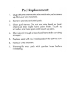
To replace a component on a flexible circuit:
1. Grasp with seizers (hemostats) the edge of the flexible circuit near the part to be removed.
2. Pull gently.
3. Apply the tip of the soldering iron to the component connections while pulling with the seizers.
Chip Components
Use either the RLN-4062 Hot-Air Repair Station or the Motorola 0180381B45 Repair Station for chip
component replacement. When using the 0180381B45 Repair Station, select the TJ-65 mini-
thermojet hand piece. On either unit, adjust the temperature control to 700 degrees F. (370 degrees
C), and adjust the airflow to a minimum setting. Airflow can vary due to component density.
• To remove a chip component, select a hot-air hand piece and position the nozzle of the hand
piece approximately 1/8” above the component to be removed. Begin applying the hot air. Once
the solder reflows, remove the component using a pair of tweezers. Using solder wick and a
soldering iron or a power desoldering station, remove the excess solder from the pads.
• To replace a chip component using a soldering iron, select the appropriate micro-tipped
soldering iron and apply fresh solder to one of the solder pads. Using a pair of tweezers, position
the new chip component in place while heating the fresh solder. Once solder wicks onto the new
component, remove the heat from the solder. Heat the remaining pad with the soldering iron and
apply solder until it wicks to the component. If necessary, touch up the first side. All solder joints
should be smooth and shiny.
NOTE
Do not attempt to puddle-out components. Prolonged application of heat may damage the
flexible circuit.

3-4 Disassembling and Reassembling the Radio — General
• To replace a chip component using hot air, select the hot-air hand piece and reflow the solder on
the solder pads to smooth it. Apply a drop of solder paste flux to each pad. using a pair of
tweezers, position the new component in place. Position the hot-air hand piece approximately 1/
8” above the component and begin applying heat. Once the solder wicks to the component,
remove the heat and inspect the repair. All joints should be smooth and shiny.
Shields
Removing and replacing shields will be done with the R-1070 station with the temperature control set
to approximately 415°F (215°C); 445°F (230°C) max.
• To remove the shield, place the circuit board in the R-1070’s holder. Select the proper heat focus
head and attach it to the heater chimney. Add solder paste flux around the base of the shield.
Position the shield under the heat-focus head. Lower the vacuum tip and attach it to the shield by
turning on the vacuum pump. Lower the focus head until it is approximately 1/8” (0.3cm) above
the shield. Turn on the heater and wait until the shield lifts off the circuit board. Once the shield is
off, turn off the heat, grab the part with a pair of tweezers, and turn off the vacuum pump.
Remove the circuit board from the R-1070’s circuit board holder.
• To replace the shield, add solder to the shield if necessary, using a micro-tipped soldering iron.
Next, rub the soldering iron tip along the edge of the shield to smooth out any excess solder. Use
solder wick and a soldering iron to remove excess solder from the solder pads on the circuit
board. Place the circuit board back in the R1070’s circuit board holder. Place the shield on the
circuit board using a pair of tweezers. Position the heat-focus head over the shield and lower it to
approximately 1/8” above the shield. Turn on the heater and wait for the solder to reflow. Once
complete, turn off the heat, raise the heat-focus head and wait approximately one minute for the
part to cool. Remove the circuit board and inspect the repair. No cleaning should be necessary.
3.5 Disassembling and Reassembling the Radio — General
Since these radios may be disassembled and reassembled with the use of only four (board to casting)
screws, it is important to pay particular attention to the snaps and tabs, and how parts align with each
other.
The following tools are required for disassembling the radio:
• Chassis opener
• Flat bladed screwdriver
• Philips head screwdriver
If a unit requires more complete testing or service than is customarily performed at the basic level,
send this unit to a Motorola Authorized Service Center. (See Chapter 1 for a list of authorized service
centers.)
The following disassembly procedures should be performed only if necessary:
• Chassis Assembly and Disassembly
• Speaker, Microphone, and Universal Connector Flex Disassembly
• Controller Board Disassembly
• Control Top Disassembly
/