Page is loading ...

INSTRUCTION MANUAL
MODEL: KC-1022ML
COPYRIGHT
© 2003
ALL
RIGHTS RESER
VED BY
KING CANADA TOOLS INC.
10” X 22”
GEARHEAD METAL LATHE

IMPORTANT INFORMATION
2
2
-
-
Y
Y
E
E
A
A
R
R
LIMITED WARRANTY
FOR THIS 10” X 22” METAL LATHE
K
K
I
I
N
N
G
G
C
C
A
A
N
N
A
A
D
D
A
A
T
T
O
O
O
O
L
L
S
S
OFFERS A 2-YEAR LIMITED WARRANTY
FOR INDUSTRIAL USE.
PROOF OF PURCHASE
Please keep your dated proof of purchase for warranty and servicing purposes.
REPLACEMENT PARTS
Replacement parts for this tool are available at our authorized KING CANADA service centers across Canada. For servicing, contact
or return to the retailer where you purchased your product along with your proof of purchase.
LIMITED TOOL WARRANTY
KING CANADA makes every effort to ensure that this product meets high quality and durability standards. KING CANADA warrants to
the original retail consumer a 2-year limited warranty as of the date the product was purchased at retail and that each product is free
from defects in materials. Warranty does not apply to defects due directly or indirectly to misuse, abuse, negligence or accidents,
repairs or alterations and lack of maintenance. KING CANADA shall in no event be liable for death, injuries to persons or property or
for incidental, special or consequential damages arising from the use of our products. To take advantage of this warranty, the product
or part must be returned for examination by the retailer. Shipping and handling charges may apply. If a defect is found, KING CANADA
will either repair or replace the product.
PARTS DIAGRAM & PARTS LISTS
Refer to the Parts section of the King Canada web site for the most updated parts diagram and parts list.
K
K
I
I
N
N
G
G
C
C
A
A
N
N
A
A
D
D
A
A
T
T
O
O
O
O
L
L
S
S
I
I
N
N
C
C
.
.
D
D
O
O
R
R
V
V
A
A
L
L
,
,
M
M
O
O
N
N
T
T
R
R
E
E
A
A
L
L
,
,
Q
Q
U
U
E
E
B
B
E
E
C
C
,
,
C
C
A
A
N
N
A
A
D
D
A
A
H
H
9
9
P
P
2
2
Y
Y
4
4

GENERAL SAFETY INSTRUCTIONS
FOR POWER TOOLS
1
. KNOW YOUR TOOL
Read and understand the owners manual and labels affixed to
the tool. Learn its application and limitations as well as its
specific potential hazards.
2. GROUND THE TOOL.
This tool is equipped with an approved 3-conductor cord and
a 3-prong grounding type plug to fit the proper grounding type
receptacle. The green conductor in the cord is the grounding
wire.
NEVER connect the green wire to a live terminal.
3. KEEP GUARDS IN PLACE.
Keep in good working order, properly adjusted and aligned.
4. REMOVE ADJUSTING KEYS AND WRENCHES.
Form habit of checking to see that keys and adjusting
wrenches are removed from tool before turning it on.
5. KEEP WORK AREA CLEAN.
Cluttered areas and benches invite accidents. Make sure the
floor is clean and not slippery due to wax and sawdust
build-up.
6. AVOID DANGEROUS ENVIRONMENT.
Don’t use power tools in damp or wet locations or expose
them to rain. Keep work area well lit and provide adequate
surrounding work space.
7. KEEP CHILDREN AWAY.
All visitors should be kept a safe distance from work area.
8. MAKE WORKSHOP CHILD-PROOF.
Use padlocks, master switches or remove starter keys.
9. USE PROPER SPEED.
A tool will do a better and safer job when operated at the
proper speed.
10. USE RIGHT TOOL.
Don’t force the tool or the attachment to do a job for which it
was not designed.
11. WEAR PROPER APPAREL.
Do not wear loose clothing, gloves, neckties or jewelry (rings,
watch) because they could get caught in moving parts. Non-
slip footwear is recommended. Wear protective hair covering
to contain long hair. Roll up long sleeves above the elbows.
1
2. ALWAYS WEAR SAFETY GLASSES.
Always wear safety glasses (ANSI Z87.1). Everyday
eyeglasses only have impact resistant lenses, they are
NOT
safety glasses. Also use a face or dust mask if cutting
o
peration is dusty.
13. DON’T OVERREACH.
Keep proper footing and balance at all times.
14. MAINTAIN TOOL WITH CARE.
Keep tools sharp and clean for best and safest performance.
Follow instructions for lubricating and changing accessories.
15. DISCONNECT TOOLS.
Before servicing, when changing accessories or attachments.
16. AVOID ACCIDENTAL STARTING.
Make sure the swich is in the ‘’OFF’’ position before plugging
in.
17. USE RECOMMENDED ACCESSORIES.
Consult the manual for recommended accessories. Follow the
instructions that accompany the accessories. The use of
improper accessories may cause hazards.
18. NEVER STAND ON TOOL.
Serious injury could occur if the tool tips over. Do not store
materials such that it is necessary to stand on the tool to reach
them.
19. CHECK DAMAGED PARTS.
Before further use of the tool, a guard or other parts that are
damaged should be carefully checked to ensure that they will
operate properly and perform their intended function. Check for
alignment of moving parts, breakage of parts, mounting, and
any other conditions that may affect its operation. A guard or
other parts that are damaged should be properly repaired or
replaced.
20. NEVER LEAVE MACHINE RUNNING
UNATTENDED.
Turn power ‘’OFF’’. Don’t leave any tool running until it comes
to a complete stop.

ELECTRICAL & TECHNICAL
INFORMATION
E
LECTRICAL INFORMATION
W
ARNING!
ALL ELECTRICAL CONNECTIONS MUST BE DONE BY A QUALIFIED ELECTRICIAN
. FAILURE TO COMPLY MAY RESULT IN SERIOUS
INJURY! ALL ADJUSTMENTS OR REPAIRS MUST BE DONE WITH THE METAL LATHE DISCONNECTED FROM THE POWER SOURCE.
FAILURE TO COMPLY MAY RESULT IN SERIOUS INJURY!
POWER SUPPLY
WARNING:
YOUR METAL LATHE MUST BE CONNECTED TO A 120V, 15-AMP. DEDICATED BRANCH CIRCUIT AND USE A 15-AMP TIME
DELAY FUSE OR CIRCUIT BREAKER. FAILURE TO CONNECT IN THIS WAY CAN RESULT IN INJURY FROM SHOCK OR FIRE.
THIS METAL LATHE MUST BE GROUNDED. IF NOT PROPERLY GROUNDED, THIS METAL LATHE CAN CAUSE ELECTRICAL SHOCK,
PARTICULARLY WHEN USED IN DAMP LOCATIONS. TO AVOID SHOCK OR FIRE, IF THE POWER CORD IS WORN OR DAMAGED IN
ANY WAY, HAVE IT REPLACED IMMEDIATELY. If your metal lathe should malfunction or breakdown, grounding provides a path of least
resistance for electric current, to reduce the risk of electric shock. This metal lathe is equipped with a cord having an equipment-grounding
conductor and grounding plug. The plug must be plugged into an appropriate outlet that is properly installed and grounded in accordance with
all local codes and ordinances.
WARNING: TO MAINTAIN PROPER GROUNDING OF YOUR METAL LATHE, DO NOT REMOVE OR ALTER THE GROUNDING PRONG IN
ANY MANNER.
TECHNICAL INFORMATION
Main Specifications
Max. swing over bed ......................................................................................................................................................................10” (254mm)
Max. swing over cross slide ............................................................................................................................................................6” (156mm)
Distance between centers ..............................................................................................................................................................22” (560mm)
Headstock
Spindle bore diameter ........................................................................................................................................................................1” (26mm)
Spindle bore taper ....................................................................................................................................................................................MT#4
Spindle speed range
..........................................................................................................................................................6 (150-2400 R.P.M.)
Gear Box
Thread cutting:
......................................................................................................................................................Inches- 24 kinds (8-72 T.P.I.)
....................................................................................................................................................................Metric- 18 kinds (0.25 - 3.5mm)
T
ool Post, Saddle, Tailstock
Top Slide travel ..........................................................................................................................................................................4-1/4” (107mm)
Cross Slide travel ......................................................................................................................................................................6-3/8” (161mm)
T
ailstock taper
............................................................................................................................................................................................MT#3
T
ailstock quill travel ......................................................................................................................................................................2-1/2” (65mm)
Diameter of Tailstock quill ............................................................................................................................................................1-1/4” (32mm)
Motor
Horsepower
................................................................................................................................................................................................1 HP
Voltage ........................................................................................................................................................................................120V, 1 phase
Amperage ..............................................................................................................................................................................................12 amp.
Motor R.P
.M.
....................................................................................................................................................................................
1720 R.P.M.
Motor frequency
..........................................................................................................................................................................................
60Hz

Before operating this metal lathe, read this instruction manual and
familiarize yourself with the required adjustments, operation
procedures, maintenance and lubrication.
C
LEANING & PREPARING LATHE
After unpacking, remove the paper (or grease found on unpainted
ground surfaces) from the machine and using a non-volatile
solvent and a brush, remove grease.
During transport and unpacking, it is likely that debris will be
present on top of the lathe. Do not move the carriage and the
tailstock until the rest of the metal lathe (mainly the bed) has been
thoroughly cleaned.
Remove all accessories and machine parts from the tool box and
install all the handles and knobs. Fix the follow rest to the carriage
using 2 cap screws and fix the steady rest inbetween the chuck
and the carriage.
Make sure that all lubrication points and oil levels have been
inspected before putting your metal lathe into operation. See
“Lubrication Points” section further in this manual before operating
your lathe.
This machine is equipped with a V-belt from the motor to the lower
rear pulley. It is advisable to check the belt tension before starting
the metal lathe. There should be no more than a 1/2” center
deflection with light finger pressure. Adjust the V-belt tension using
the tensioner as necessary. V-belts which are tensioned too
tightly will damage the bearing.
Before performing any operations, set the metal lathe on the
lowest speed and let the machine operate for 15 minutes. If
everything is functionning normally, you can proceed with
operations.
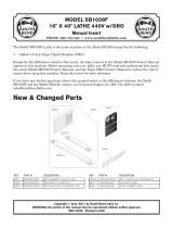
FIGURE 1
CLEANING &
GETTING TO KNOW YOUR LATHE
1- Headstock
2- Chuck safety guard
3- Steady rest
4- Tool post
5- Follow rest (not fully shown)
6- Top slide
7- Cross slide
8- Bedway
9- Tailstock
10- Control switches
11- Gear box
12- Chuck
13- Carriage
14- Feed lever
15- Thread cutting dial
16- Feed shaft
17- Gear rack
18- Thread & feed selectors
1
2
3
8
5
4
6
7
17
16
14
13
12
11
10
Getting to know your Metal Lathe
Optional Accessories available:
• KLC-3M -Live Center (MT#3)
• SS-1022 -Stand
• KM-057 -7pc. Deluxe Cutter Holder Set
9
15
18

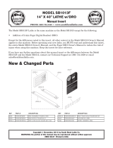
OPERATING KNOBS & LEVERS
Metal Lathe Operating Knobs & Levers (Fig.2)
Headstock Control buttons
•Control buttons 1, 2, 3 are located on the front side of the headstock.
Button 1 is the Emergency Stop button. Button 2 is the Forward/
Reverse switch which allows you to change the rotation of the
spindle and chuck. Button 3 is the Power ON button.
Quick Change Gear Box Knobs
•Knobs 4 and 5 are the thread and feed selectors, set these selectors
as indicated in the metal lathe charts depending on the thread to be
cut and the feed speed desired. Note: It will be necessary to verify
and change the gear configuration on the left side of the headstock,
check the metal lathe charts for proper gear configuration.
Caution: Always stop the spindle before changing the position of
either knobs (Knobs 4 & 5).
Carriage Assembly Levers
• Handwheel 6 is used to manually move the carriage along the
bedway of the lathe.
• The crossfeed handwheel 7 is used to manually move the cross slide
in or out.
• The top slide handwheel 11 is used to manually move the tool post.
The top slide is fully adjustable to any angle and is also used for
threading or machining an angle on a workpiece.
• The longitudinal feed lever 8 is used to engage the half nuts when
threading.
• The clamp lever 12 is used to secure the tool post block to the top
slide.
Tailstock levers
• The handwheel 9 is used to feed or retreat the tailstock quill. Tip:
Turning the handwheel completely couterclockwise until a full stop
will automatically eject the turning tool used.
• The tailstock quill lock lever 10 prevents the quill from moving.
9
11
10
6
7
8
1
3
4
5
FIGURE 2
12
2

METAL LATHE CHARTS
Metal Lathe Charts
Below are all the charts which are found on the metal lathe plates. We have included these charts in this manual for reference purposes, in case
any or many plates have been damaged and are no longer readable.
FIGURE 3- 6 Spindle Speeds Chart
FIGURE 4- Inch Thread Chart
FIGURE 6- Feed Rate Chart
FIGURE 5- Metric Thread Chart
FIGURE 7- Thread Dial Indicator Chart

ADJUSTMENTS & OPERATION
Mounting or removing chuck or face plate
Before mounting a chuck (A) Fig.8, face plate or other attachments, it is
very important that the mounting surfaces on both the spindle nose and
the attachment are extremely clean.
The chuck (A) and chuck plate (B) are held together using cap screws,
t
hese two attachments are screwed (left handed thread) onto the spindle
nose and secured by two fixing brackets (C) and cap screws (D).
To remove the chuck from the spindle, follow these instructions;
1) Remove cap screws (D) and fixing brackets (C).
2) Now the chuck and chuck plate must be unscrewed from the spindle
nose. Note: To tighten, turn chuck counterclockwise. To loosen, turn
chuck clockwise. It is necessary to use the chuck key (placed in chuck)
and an additional rod (placed in spindle nose holes), force in opposite
directions to unscrew chuck.
Adjusting and reversing chuck jaws
Chuck jaws (A) Fig.9 can be opened or closed by using the camlock key
in the jaw adjustment cams (B). Turning the camlock key (C) clockwise will
close the jaw opening and counterclockwise will open the jaw opening.
Before reversing the direction of the chuck jaws, two major points must be
followed every time.
1) The chuck jaws are numbered (ex.: 3 jaw chuck- 1,2,3) and must be
placed in numerical order into the chuck.
2) If the chuck jaws are to be removed, you must replace them in the
identical slot which they were taken out of. (Make sure they are also in
numerical order).
To remove chuck jaws, open jaw opening all the way using camlock key
until the jaws practically fall out. Do not let the jaws fall, hold them while
you open the jaw opening. Change the direction of each jaw and apply
pressure on them towards the center of the chuck. Turn camlock key
clockwise and make sure all jaws engage the spiral mechanism.
Installing and operating follow rest and steady rest
The follow and steady rests serve as workpiece supports during
operations. Install the follow rest (A) Fig.10 to the saddle (B) using 2 cap
screws. Install the steady rest (C) to the bedway (D) (inbetween the
carriage and the chuck) using the clamp shoe, bolt and lock nut assembly.
The follow rest is installed near the cutting tool to give additional support.
If the follow rest would not be used, the cutting tool pressure on the
workpiece could warp your workpiece and give undesired results.
Position workpiece in the steady rest and the follow rest. Secure
workpiece in rests by tightening the centers but do not overtighten.
FIGURE 8
FIGURE 9
FIGURE 10

ADJUSTMENTS & OPERATION
Tailstock Adjustments & Operation
The tailstock can be moved freely on the bedway and fastened at any
position by tightening tailstock hex. nut (A) Fig.11. The tailstock quill can
b
e moved in and out by using handwheel (B) and then fastened in place
using quill locking lever (C). Dead centers or drill chucks are normally
installed in the tailstock quill.
An important adjustment and verification must be done in order to obtain
the best results using your tailstock. The tailstock must be perfectly
aligned with the chuck. Fix a ground steel bar inbetween the chuck center
and the tailstock center. Using a precise measuring tool (dial indicators),
make sure the distance at both ends of the ground steel bar are the same
using the top slide as starting reference point, see Fig.12. If the distance
is not the same, then a crosswise adjustment to the tailstock is necessary.
Adjust set screws (D) Fig.11 on both sides of the tailstock until the distance
at both ends of the ground steel bar are the same.
Tool Post Adjustments & Operation
The 4-way tool post assembly (A) Fig.13 can lock up to 4 cutting tools into
place at a time (use at least 2 cap screws per cutting tool). The tool post
can pivot 360
0
for various cutting situations. To pivot the tool post
assembly, loosen handle (B) and pivot tool post, retighten handle.
Cross & Top Slide Adjustments & Operation
The cross slide handwheel (A) Fig.14 is used to feed the entire cross slide,
top slide and tool post with cutting tool towards the workpiece.
After time
the cross slide gib (B) may become loose or too tight and an adjustment
may be necessary. To adjust the gib (B), tighten or loosen the hex. nuts
and set screws (C) on the right side until the cross slide moves freely
without play.
The top slide handwheel (D) feeds the entire top slide and tool post with
cutting tool towards the chuck or the tailstock end of the lathe. After time
the top slide gib may become loose or too tight and an adjustment may be
necessary. The top slide can be pivoted to a desired angle, to adjust the
angle of the top slide simply loosen hex. nuts (E) on both sides of the top
slide base and pivot. Retighten hex. nuts (E) after adjustment.
FIGURE 11
FIGURE 12
FIGURE 13
FIGURE 14

ADJUSTMENTS & OPERATION
Feed and Thread Selection
T
o set the desired feed rate and thread selection, look at the charts in
Fig’s.4 & 6 and determine the feed rate desired in relation to the thread to
b
e cut. Once you have determined the job at hand, place the selectors (A
& B) Fig.15 in the appropriate positions.
If Metric Threads are desired, change gears must be installed as shown in
chart Fig.5 and as described below.
Change gears
To obtain imperial or metric threads the proper change gears must be
installed inside the left side cover. Unscrew cover lock knob to gain access
to the left side of the headstock.
Before changing gears, determine the thread pitch desired and look at
which gear configuration is needed. See Thread charts as reference.
Before trying to remove a gear, all the gears need to be distanced from
each in order to be removed. To distance the gears from each other,
unscrew cap screw (A) Fig.16 which secures the pivot bracket (B). This will
allow you to lower the center gear assembly. Now unscrew special lock
screw (C) and slide the center gears off the pivot bracket (B). Now all the
gears are distanced and ready to be changed.
To replace the top gear (A) Fig 17, remove “C” clip (B) which holds it in
place. Replace with appropriate gear and secure with “C” clip (B).
To replace the bottom gear (C), remove cap screw and washer (D).
Replace with appropriate gear and secure it using the same cap screw and
washer (D) removed previously.
The rear middle gear with 127T (E) does not get interchanged but the front
middle gear (F) does.
To replace the front middle gear (F), remove the
retaining plate (G). Replace with appropriate gear and secure with
retaining plate (G).
Once the change gears are in place, slide middle gears (E & F) back onto
the pivot bracket until it snug against the bottom gear (C), secure with
special lock screw (H) and make sure the retaining plate (G) is in place
before securing middle gears. Raise the middle gears assembly upwards
until it is snug with the top gear (A) and secure pivot bracket cap screw (A
& B) Fig.16. Close the side cover and lock it using the same lock knob
unscrewed previously.
FIGURE 15
FIGURE 16
FIGURE 17

ADJUSTMENTS & OPERATION
FIGURE 18
Longitudinal Auto-Power Feed
To obtain a desired feed rate, the correct gear configuration must be set
as shown in “Feed Rate” chart Fig.6. The longitudinal auto-feed lever
(A) Fig.18 is used to engage the half-nuts for longitudinal feeding of the
carriage. This lever has 2 positions; the lower position engages the
half-nuts to start longitudinal feed and the upper position disengages
the half-nuts to stop longitudinal feed.
For imperial threading operations, the auto-power feed can be engaged
and disengaged at any time. To reverse the logitudinal feed, disengage
the halft-nuts (stops longitudinal feed) and manually move the carriage
back using the carriage handwheel. The auto-power feed can then be
engaged again for a second pass.
Note: The only difference in metric threading is the half-nuts must be
engaged during the entire threading operation. The thread dial can not
be used for metric threading operations.
Thread Cutting Operation
In order to obtain the desired thread, all change gears must be installed
in accordance to the thread charts. Failure to do so will give incorrect
threads.
When cutting inch threads, the auto-power feed and thread cutting dial
(B) Fig.18 are used. The threading dial Indicator chart Fig.7 specifies at
which point a thread can be engaged using the threading dial.
When cutting metric threads, the auto-power feed is used. Note: The
half-nuts must be engaged during the entire threading operation. The
thread dial can not be used for metric threading operations.
Thread Cutting Dial Operation
The thread cutting dial (B) Fig.18 is used to engage the half nuts with
the leadscrew in the same thread that has been previously cut. The
threading dial Indicator chart Fig.7 specifies at which point a thread can
be engaged using the threading dial.
Changing spindle speed
In order to obtain the desired spindle speed, the belt configuration on
the pulleys must be set as shown in spindle speed chart Fig. 3. The
letters correspond to the required pulleys and the numbers correspond
to the required pulley step. Pulley A Fig.3 is the motor pulley and
pulley C Fig.3 is the spindle pulley. To obtain a spindle speed of 150
RPM, set the belt on step 1 of pulleys B & C Fig.3.
Tensionning Belt
A tensionner (A) Fig.19 is supplied to tension the belt. Once the belt is
in position, lower the tensionner against the belt and apply necessary
tension. Lock tensioner in place using open end key supplied to lock
hex. nut behind support plate (B). Make sure the tensionner does not
come in contact with any other part of the pulley or belt before locking
it into place.
FIGURE 19

LUBRICATION POINTS
Before operating the metal lathe, check the oil level and lubricate all sliding surfaces such as the half nut, worm gear, feed rod, handle rod,
tailstock quill before and after operating. Follow the main lubrication points illustrated below.
Lubrication Notes
Note: After running for the first 3 months, change the gear box oil (20W Machine Oil). Change oil once a year after first initial oil change. Remove
set screw on left side of gear box and drain oil, replace set screw. To fill gear box with oil, remove set screw on right side of gear box and pour
oil into gear box until it reaches the 3/4 mark on the oil level indicator.
Lubrication Points
Headstock lubrication points (1).
Gear Box lubrication points (2 & 3).
Gear Change lubrication points (4). Oil nipples and grease gears.
Saddle lubrication point (5).
Handwheel lubrication points (6).
Feedscrew & Bracket lubrication points (7).
Tailstock lubrication points (8).
Tool Post Slide lubrication point (9).
Top slide lubrication points (10). (Behind Tool Post)
Rack lubrication (11). Grease.
A light oil should be used on the bedway and all other reflective parts such as the tailstock quill.
9
10
8
7
6
11
4
5
1
3
2
FIGURE 20
PARTS DIAGRAM & PARTS LISTS
Refer to the Parts section of the King Canada web site for the most updated parts diagram and parts list.
/