Page is loading ...

INSTRUCTION MANUAL
MODEL: KC-1640ML
COPYRIGHT © 2013 ALL RIGHTS RESERVED BY KING CANADA TOOLS INC.
16” X 40” HIGH PRECISION
“TOOLROOM” METAL LATHE
09/2013

WARRANTY INFORMATION
2-YEAR
LIMITED WARRANTY
FOR THIS 16” X 40” METAL LATHE
KING CANADA TOOLS
OFFERS A 2-YEAR LIMITED WARRANTY
FOR INDUSTRIAL USE.
PROOF OF PURCHASE
Please keep your dated proof of purchase for warranty and servicing purposes.
REPLACEMENT PARTS
Replacement parts for this product are available at our authorized King Canada service centers across Canada.
LIMITED TOOL WARRANTY
King Canada makes every effort to ensure that this product meets high quality and durability standards. King Canada warrants to the
original retail consumer a 2-year limited warranty as of the date the product was purchased at retail and that each product is free from
defects in materials. Warranty does not apply to defects due directly or indirectly to misuse, abuse, normal wear and tear, negligence
or accidents, repairs done by an unauthorized service center, alterations and lack of maintenance. King Canada shall in no event be
liable for death, injuries to persons or property or for incidental, special or consequential damages arising from the use of our products.
To take advantage of this limited warranty, return the product at your expense together with your dated proof of purshase to an
authorized King Canada service center. Contact your retailer or visit our web site at www.kingcanada.com for an updated listing of our
authorized service centers. In cooperation with our authorized serviced center, King Canada will either repair or replace the product if
any part or parts covered under this warranty which examination proves to be defective in workmanship or material during the
warranty period.
NOTE TO USER
This instruction manual is meant to serve as a guide only. Specifications and references are subject to change without prior notice.
PARTS DIAGRAM & PARTS LISTS
Refer to the Parts section of the King Canada web site for the most updated parts diagram and parts list.
KING CANADA INC. DORVAL, QUÉBEC, CANADA H9P 2Y4
www.kingcanada.com

GENERAL & SPECIFIC SAFETY
INSTRUCTIONS FOR METAL LATHES
GENERAL SAFETY INSTRUCTIONS
1. KNOW YOUR TOOL
Read and understand the owners manual and labels affixed to
the tool. Learn its application and limitations as well as its
specific potential hazards.
2
. GROUND THE TOOL.
This tool is equipped with an approved 3-conductor cord. The
green conductor in the cord is the grounding wire. NEVER
connect the green wire to a live terminal.
3. KEEP GUARDS IN PLACE.
Keep in good working order, properly adjusted and aligned.
4. REMOVE ADJUSTING KEYS AND WRENCHES.
Form habit of checking to see that keys and adjusting
wrenches are removed from tool before turning it on.
5. KEEP WORK AREA CLEAN.
Cluttered areas and benches invite accidents. Make sure the
floor is clean and not slippery due to wax and sawdust
build-up.
6. AVOID DANGEROUS ENVIRONMENT.
Don’t use power tools in damp or wet locations or expose
them to rain. Keep work area well lit and provide adequate
surrounding work space.
7. KEEP CHILDREN AWAY.
All visitors should be kept a safe distance from work area.
8. MAKE WORKSHOP CHILD-PROOF.
Use padlocks, master switches or remove starter keys.
9. USE PROPER SPEED.
A tool will do a better and safer job when operated at the
proper speed.
10. USE RIGHT TOOL.
Don’t force the tool or the attachment to do a job for which it
was not designed.
11. WEAR PROPER APPAREL.
Do not wear loose clothing, gloves, neckties or jewelry (rings,
watch) because they could get caught in moving parts. Non-
slip footwear is recommended. Wear protective hair covering
to contain long hair. Roll up long sleeves above the elbows.
12. ALWAYS WEAR SAFETY GLASSES.
Always wear safety glasses (ANSI Z87.1). Everyday eye-
glasses only have impact resistant lenses, they are
NOT
safety glasses. Also use a face or dust mask if cutting opera-
tion is dusty.
1
3. DON’T OVERREACH.
Keep proper footing and balance at all times.
14. MAINTAIN TOOL WITH CARE.
Keep tools sharp and clean for best and safest performance.
Follow instructions for lubricating and changing accessories.
15. DISCONNECT TOOLS.
Before servicing, when changing accessories or attachments.
16. AVOID ACCIDENTAL STARTING.
Make sure the swich is in the ‘’OFF’
’ position before plugging
in.
17. USE RECOMMENDED ACCESSORIES.
Consult the manual for recommended accessories. Follow the
instructions that accompany the accessories. The use of
improper accessories may cause hazards.
18. NEVER STAND ON TOOL.
Serious injury could occur if the tool tips over. Do not store
materials such that it is necessary to stand on the tool to reach
them.
19. CHECK DAMAGED PARTS.
Before further use of the tool, a guard or other parts that are
damaged should be carefully checked to ensure that they will
operate properly and perform their intended function. Check for
alignment of moving parts, breakage of parts, mounting, and
any other conditions that may affect its operation. A guard or
other parts that are damaged should be properly repaired or
replaced.
20. NEVER LEAVE MACHINE RUNNING
UNATTENDED.
Turn power ‘’OFF’’. Don’t leave any tool running until it comes
to a complete stop.
SPECIFIC SAFETY INSTRUCTIONS FOR METAL LATHES
1. CLEANING MACHINE:
T
o avoid entanglement and lacerations,
do not clear chips by hand. Use a brush, and never clear chips
while the lathe is operating.
2. USING CORRECT T
OOLING:
Always select the right cutter for
the job, and make sure cutters are sharp.
The right tool
decreases strain on the lathe components and reduces the risk
of unsafe cutting.
3. ELIMINATING PROJECTILE HAZARDS: Always remove the
chuck key, and never walk away from the lathe with the chuck
key installed. Always make sure workpiece is securely held in
chuck before starting lathe. A workpiece thrown from the chuck
could cause severe injury.
4. AVOIDING OVERLOADS: Always use the appropriate feed and
speed rates.
5. PREVENTING A CUTTING TOOL/CHUCK CRASH: Always
release automatic feeds after completing a job, and never leave
lathe unattended while it is running.
6.
A
VOIDING ST
ARTUP INJURIES:
Make sure workpiece, cutting
tool, and tool post have adequate clearance before starting
lathe. Check chuck clearance and saddle clearance before
starting the lathe. Make sure spindle RPM is set correctly for part
diameter before starting the lathe. Large parts can be ejected
from the chuck if the chuck speed is set too high.
7. CHUCK SAFETY: Chucks are surprisingly heavy and awkward
to hold, so protect your hands and the lathe ways. Always use a
chuck cradle or piece of plywood over the lathe ways.
8. WORKPIECE SUPPORT
:
Support a long workpiece if it extends
from the headstock so it will not wobble violently when the lathe
is turned ON. If workpiece extends more than 2.5 times its
diameter from the chuck, support it by a center or steady rest, or
it may deflect and fall out of the chuck while cutting.
9. AVOIDING ENTANGLEMENT INJURIES: Never attempt to slow
or stop the lathe chuck by hand. Tie back long hair, ponytails,
loose clothing, and sleeves so they do not dangle.

ELECTRICAL & TECHNICAL
INFORMATION
ELECTRICAL INFORMATION
WARNING!
ALL ELECTRICAL CONNECTIONS MUST BE DONE BY A QUALIFIED ELECTRICIAN
. FAILURE TO COMPLY MAY RESULT IN SERIOUS
I
NJURY! ALL ADJUSTMENTS OR REPAIRS MUST BE DONE WITH THE METAL LATHE DISCONNECTED FROM THE POWER SOURCE.
FAILURE TO COMPLY MAY RESULT IN SERIOUS INJURY!
POWER SUPPLY
WARNING:
THIS METAL LATHE MUST BE ‘HARDWIRED’ (connected directly to the circuit breaker without the use of a plug). We recommend
that only a qualified electrician do the initial ‘Hardwiring’ of this metal lathe.
WARNING:
YOUR METAL LATHE MUST BE CONNECTED TO A 600V, 15-AMP (MINIMUM) BRANCH CIRCUIT WITH A 15-AMP TIME DELAY FUSE
OR CIRCUIT BREAKER. FAILURE TO CONNECT IN THIS WAY CAN RESULT IN INJURY FROM SHOCK OR FIRE.
THIS METAL LATHE MUST BE GROUNDED
. IF NOT PROPERLY GROUNDED, THIS METAL LATHE CAN CAUSE ELECTRICAL SHOCK,
PARTICULARLY WHEN USED IN DAMP LOCATIONS. TO AVOID SHOCK OR FIRE, IF THE POWER CORD IS WORN OR DAMAGED IN
ANY WAY, HAVE IT REPLACED IMMEDIATELY.
TECHNICAL INFORMATION KC-1640ML
Main Specifications
Max. swing over bed......................................................................................................................................................................................16”
Max. swing over saddle gap ..........................................................................................................................................................................22”
Max. swing over cross slide ..........................................................................................................................................................................10”
Distance between centers ............................................................................................................................................................................40”
Headstock
Spindle bore diameter......................................................................................................................................................................................2”
Spindle bore taper
....................................................................................................................................................................................
MT#6
Spindle speed range ..........................................................................................................................................................16 (45-1800 R.P.M.)
Gear Box
Inch threads (number and range)................................................................................................................................................45 (2-72 T.P.I.)
Metric threads (number and range) ..........................................................................................................................................39 (0.2 - 14mm)
Modular pitches (number and range) ......................................................................................................................................18 (0.3 - 3.5 MP)
Diametrical pitches (number and range)......................................................................................................................................21 (8 - 44 DP)
Tool Post, Saddle, Tailstock
Top Slide travel ..........................................................................................................................................................................................5-1/2”
Cross Slide travel ......................................................................................................................................................................................8-1/2”
T
ailstock taper ............................................................................................................................................................................................MT#4
Tailstock quill travel....................................................................................................................................................................................4-3/4”
Diameter of Tailstock quill ................................................................................................................................................................................2”
Motor
Speeds ............................................................................................................................................................................................
2 (high/low)
Horsepower..............................................................................................................................................................................................
3-4 HP
Voltage ........................................................................................................................................................................................
600V, 3 phase
Amperage ................................................................................................................................................................................................5 amp.
Motor frequency..........................................................................................................................................................................................
60Hz

W
arning!
Before operating this metal lathe, read this instruction
manual and familiarize yourself with the required adjustments,
operation procedures, maintenance and lubrication.
CLEANING & PREPARING LATHE BEFORE THE FIRST TEST RUN
After unpacking, remove the paper (or grease found on unpainted
ground surfaces) from the machine and using a non-volatile solvent
and a brush, remove grease.
During transport and unpacking, it is likely that debris will be present
on top of the lathe. Do not move the carriage and the tailstock until
the rest of the metal lathe (mainly the bed) has been thoroughly
cleaned.
Remove all accessories and machine parts from the tool box and
install all the handles and knobs. Fix the follow rest to the carriage
using 2 cap screws and fix the steady rest inbetween the chuck and
the carriage.
Make sure that all lubrication points and oil levels have been
inspected before putting your metal lathe into operation. See
“Lubrication Points” in the maintanance section in this manual before
operating your lathe.
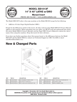
GETTING TO KNOW YOUR LATHE,
CLEANING & PRETEST RUN
1- Motor speed switch (high/low)
2- Gearbox speed range lever
3- Gearbox ratio lever
4- Gearbox ratio lever
5- Gearbox ratio lever
6- Power ON light
7- Coolant pump switch
8- Emergency stop button
9- Inching/Jogging button
10- Gearbox high/low range lever
1
1
- Leadscrew/Feed rod direction lever
12- Headstock speed lever
13- Headstock low/high range lever
14- Chuck guard with limit switch
15- Chuck
16- Steady rest
17- Follow rest
18- Tool post transparent guard
19- Quick change tool post
20- Coolant nozzle
21- Halogen lamp
22- Compound slide handwheel
23-
T
ailstock sleeve lock lever
24- Tailstock
25-
T
ailstock handwheel
26-
T
ailstock lock lever
27- Carriage oil hand pump
28- Leadscrew protector
29- Spindle rotation On/Of
f lever
30-
Threading dial
31- Halfnut lever
32- Carriage feed direction knob
33- Feed selector lever
34- Cross slide handwheel
35- Carriage handwheel
36- Foot brake
37- Manual micrometer stop
38- Main On/Of
f switch
39- Spindle/gear change cover
40- Coolant pump/coolant reservoir
41- Coolant screen
FIGURE 1

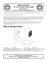
TEST RUN
TEST RUN
WARNING!
TO AVOID CAUSING SEVERE DAMAGE TO THE METAL LATHE, NEVER SHIFT
LATHE GEARS WHEN LATHE IS OPERATING.
Make sure the half-nut lever and the
f
eed lever are disengaged before starting the metal lathe. The lathe will feed the
carriage towards the chuck or the tailstock.
A test run is recommended to determine if there are any problems before operating the
lathe.
1. Turn the main On/Off switch (#38) Fig.1 to the On position.
2. Make sure the headstock oil level is full. See oil sight glass (A) Fig.3 Refer to
maintenance section for lubrication instructions.
3. Make sure the chuck is mounted securely to the spindle. Refer to Mounting
Chuck/Faceplate section for instructions.
4. Disengage the feed lever (A) Fig.2 (horizontal position), disengage half-nut lever (B)
(pull upwards), move spindle rotation On/Off lever (C) to the centre neutral position
(motor Off). See Fig.2 as reference.
5. Rotate emergency stop button (B) Fig.3 clockwise until it pops out.
6. Turn the motor high/low range switch (E) Fig.3 to the “1” position and the green
power On light (C) Fig.3 will turn on.
7. Push the jog button (D) Fig.3 several times, the motor will turn On momentarily and
the chuck will rotate.
8. Position headstock levers as shown in Fig.4. Position the headstock speed lever
(A) Fig.4 to the left and the gearbox high/low lever (B) pointing downwards to
obtain a spindle speed of 330 RPM.
9. Move the spindle rotation On/Off lever (C) Fig.2 downwards until the chuck turns.
Push the emergency stop button to stop the lathe.
10. Reposition the spindle rotation On/Off lever (C) Fig.2 to the centre neutral position,
reset emergency stop button and restart the lathe.
11. Push the foot brake (#36) Fig.1, the lathe should come to a complete stop.
12. Return the spindle rotation On/Off lever to the stop position, restart the lathe, let the
lathe run for 10 minutes at 330 RPM in both directions.
13.
After 10 minutes, stop the lathe, position headstock levers to the next highest RPM.
Run for 10 minutes in both directions.
14. Repeat for the remaining RPM
ranges increasing in RPM. Once done, the break-in
of the lathe is now complete.
15. Drain and refill lubricant in the headstock. Refer to maintenance section for
lubrication instructions.
FIGURE 2
FIGURE 3
FIGURE 4

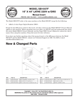
ADJUSTMENTS & OPERATION
Mounting or removing chuck or face plate
The 3-jaw chuck comes installed on the lathe, all three jaws move in unison when
adjusted. The supplied 4-jaw chuck has independant jaws and is used for square or
unevenly shaped workpieces. If neither chuck can hold your workpiece, the faceplate
can be mounted using its t-bolts and slots to secure workpiece. The chucks and
faceplate come with a D-6 camlock mount. Before mounting a chuck or face plate, it is
very important that the mounting surfaces on both the spindle nose and the attachment
are extremely clean.
All the camlocks (A) Fig.5 should be in their release position, the camlock mark line (B)
line up with the spindle nose mark line (C). Mount the chuck or faceplate onto the
spindle nose, once in position, each camlock must be tightened and locked into place.
Camlocks (A) are tightened by turning them clockwise using the provided Camlock Key.
The cams are properly locked into place when the camlock mark line (B) is inbetween
the 2 V’s (D) on the spindle nose, see Fig.5.
Adjusting and reversing chuck jaws
Chuck jaws (A) Fig.6 can be opened or closed by using the camlock key (B) in the jaw
adjustment cams (C). Turning the camlock key clockwise will close the jaw opening and
counterclockwise will open the jaw opening.
Before reversing the direction of the chuck jaws, two major points must be followed
every time.
1) The chuck jaws are numbered (ex.: 3 jaw chuck- 1,2,3) and must be placed in
numerical order into the chuck.
2) If the chuck jaws are to be removed, you must replace them in the identical slot which
they were taken out of. (Make sure they are also in numerical order).
To remove chuck jaws, open jaw opening all the way using camlock key until the jaws
practically fall out. Do not let the jaws fall, hold them while you open the jaw opening.
Change the direction of each jaw and apply pressure on them towards the center of the
chuck. Turn camlock key clockwise and make sure all jaws engage the spiral
mechanism.
Installing and operating follow rest and steady rest
The follow and steady rests serve as workpiece supports during operations. Install the
follow rest (A) Fig.7 to the carriage using 2 cap screws. Install the steady rest (B) to the
bedway (inbetween the carriage and the chuck) using the clamp shoe, bolt and lock nut
assembly
.
The follow rest is installed near the cutting tool to give additional support. If the follow
rest would not be used, the cutting tool pressure on the workpiece could warp your
workpiece and give undesired results.
Position workpiece in the steady rest and the follow rest. Secure workpiece in rests by
adjusting the position each bearing fingers (refer to knobs C & E) until they all contact
the workpiece. Do not over tighten the bearing fingers. Once adjusted, tighten the lock
knobs (D & F) of each bearing finger
.
FIGURE 5
FIGURE 6
FIGURE 7

ADJUSTMENTS & OPERATION
Tailstock Adjustments & Operation
The tailstock (A) Fig.8 can be moved freely on the bedway and fastened at any
position using the tailstock lock lever (B). The tailstock quill (C) can be moved in and
o
ut by using handwheel (D) and then locked in place using quill locking lever (E).
Dead centers or drill chucks are normally installed in the tailstock quill.
An important adjustment and verification must be done in order to obtain the best
r
esults using your tailstock. The tailstock must be perfectly aligned with the chuck. Fix
a ground steel bar inbetween the chuck centre and the tailstock centre. Using a
precise measuring tool, make sure the distance at both ends of the ground steel bar
are the same using the top slide as starting reference point, see Fig.9. If the distance
is not the same, then an cross-wise adjustment to the tailstock is necessary.
To make a cross-wise adjustment, unlock tailstock lever (B) Fig.8 and adjust set
screws (F) on both sides of the tailstock until the distance at both ends of the ground
steel bar are the same.
Tool Post & Holder Adjustments & Operation
The tool post assembly (A) Fig.10 is used to lock the cutting tool into place at the
desired height and angle. The tool post can pivot 360
0
for various cutting situations.
To pivot the tool post assembly, loosen lock nut (B) and pivot tool post, retighten lock
nut. The tool post comes with a tool holder (C) which can be adjusted to a desired
height using the shaft and nuts mechanism (D) to raise or lower the tool holder. Once
the height of the tool holder is determined, use tool post lock handle (E) to lock tool
holder in place. The tool holder has 4 locking set screws (F) which lock the cutting
tool in place.
During all operations, the tool post safety guard (K) Fig.11 must be in the closed
position as shown in order to protect user.
Cross & Top Slide Adjustments & Operation
The cross slide handwheel (A) Fig.11 is used to feed the cross slide (B), top slide and
tool post with cutting tool towards the workpiece. After time the cross slide gib may
become loose or too tight and an adjustment may be necessary. To adjust the gib,
tighten or loosen the flat head bolt (C) until the cross slide moves freely without play.
The top slide handwheel (D) feeds the top slide (E) and tool post with cutting tool
towards the chuck or the tailstock end of the lathe. After time the top slide gib may
become loose or too tight and an adjustment may be necessary. To adjust the gib,
tighten or loosen the flat head bolt (F) until the top slide moves freely without play.
The top slide (E) can be pivoted to a desired angle, to adjust the angle of the top slide
simply loosen cap screws (G) on both sides of the top slide base. Use the angle scale
(H) on the top of the cross slide as reference. Retighten cap screws once the
adjustment is made.
The cross and top slides come with imperial and metric dials (I & J) Fig.1
1. Simply
turn the dials 180 degrees to switch from metric to imperial or vise versa.
FIGURE 8
FIGURE 9
FIGURE 10
FIGURE 1
1

METAL LATHE CHARTS
Metal Lathe Charts
B
elow are all the charts which are found on the metal lathe plates. We have included these charts in this manual for reference purposes, in
case one or many plates have been damaged and are no longer readable.
Change Gears Chart
Modular and Diametrical Thread Pitch Chart
Feed Speeds Chart
FIGURE 12
Metric Thread Pitch Chart
FIGURE 13
Imperial Thread Pitch Chart
FIGURE 14
Thread Dial Indicator Chart
FIGURE 15

METAL LATHE CHARTS
Metal Lathe Charts
Below are all the charts which are found on the metal lathe plates. We have included these charts in this manual for reference purposes, in
case one or many plates have been damaged and are no longer readable.
Spindle Speed Chart
FIGURE 16
Control Panel/Feed Rate/Thread Selection Chart
FIGURE 17

ADJUSTMENTS & OPERATION
Spindle Speeds
The spindle speed (spindle RPM) is controlled by two levers (A & B) Fig.18 at the top
of the headstock and the 2 speed motor switch (C). The 2 speed motor allows for low
o
r high range speed options presented in columns 1 (D) and 2 (E). Fig.18 shows an
example of how to set the spindle speed to 1170 RPM.
1. Move the 2 speed motor switch (C) Fig.18 to the “1” position as shown.
N
ote: Position “1” activates both #1 columns (D) on the speed chart.
Note: Position “2” activates both #2 columns (E) on the speed chart.
Note: Position “0” cuts power to the motor.
2. Move the headstock low/high range lever (A) so that it points towards which ever
range column your RPM is listed.
3. Move the headstock speed lever (B) so that the indicator points to
1170 RPM at the top of column number “1”.
Gearbox Speed Range Lever
Warning!
Only shift the gearbox levers when the spindle speed is less than 500 RPM
and the gearbox speed range lever is in neutral.
The gearbox consists of a few levers to control the feed rod and leadscrew feed rates
in relation with the spindle speed. Based on the threading and feed rate chart, you
can shift the gearbox to obtain a large array of feed rates.
1. Depending on the position of the spindle range lever (A) Fig.19, the gearbox
speed range lever (B) has 8 settings for various threading and power feed
operations.
2. When the spindle range lever (A) is pointing towards the white spindle speed
chart (C), the right hand selections 1, 3, 5, 7 (D) are available.
3. When the spindle range lever (A) is pointing towards the red spindle speed chart (E),
the left hand selections 2, 4, 6, 8 (F) are available.
FIGURE 18
FIGURE 19

ADJUSTMENTS & OPERATION
Feed Rod and Leadscrew
Warning!
Only shift the gearbox levers when the spindle speed is less than 500 RPM
and the gearbox speed range lever is in neutral.
1. The leadscrew/feed rod lever (A) Fig.20 engages and disengages the leadscrew
a
nd feed rods simultaneously. When moved up or down, the rotation of the lead
screw and feed rods are simultaneously reversed.
2
. The gearbox high/low range lever (B) Fig.20 will put the gearbox in high range (H),
low range (L) or neutral (I).
Warning! Make sure to loosen the carriage lock bolt (A) Fig.21 before any power feed
or threading operations. This carriage lock bolt is used to increase stability
when performing facing operations.
Gearbox Ratio Levers
Warning!
Only shift the gearbox levers when the spindle speed is less than 500 RPM
and the gearbox speed range lever is in neutral.
The gearbox has a series of levers used for controlling the feed rod and leadscrew
feed rates in relation to the spindle speed. Based on the threading and feed rate
chart, you can shift the gearbox to accomodate and large range of feed speeds.
1. The 3 gearbox range levers (A, B & C) Fig.22 which have multiple lettered positions,
when placed according to the threading chart and example shown in Fig.24, you
can quickly change the feed rate.
2. The example in Fig.24 shows the lathe set up for 3.5mm metric thread.
3. For threading, make sure the change gears (A) Fig.23 are set as shown in the
metric/imperial threading gear positions illustration (A) Fig.24.
4. In the metric thread chart (B) Fig.24, a combination of letters and numbers
appear next to the 3.5mm (LCR8Y), position levers in the corresponding positions
as shown in Fig.24.
FIGURE 20
FIGURE 24
FIGURE 21
FIGURE 22
FIGURE 23

ADJUSTMENTS & OPERATION
Power Feed Direction Knob
This lathe can cut left and right while feeding, or in and out when facing. The feed
direction is controled by the feed direction knob (A) Fig.25.
Half-nut Lever and Thread Dial
The half-nut lever (A) Fig.26 clamps and releases the half-nut, which clamps around
the leadscrew. Only engage this lever when cutting threads, use the feed lever (B) for
general purpose feeding.
This lathe has imperial leadscrews, therefore the thread dial chart (A) Fig.27 can only
be used for imperial (inch) threads. For all other threading operations, the half-nut
lever (A) Fig.26 must stay engaged until the threads are complete.
If the feed lever (B) Fig.26 is engaged, the half-nut lever will be blocked from use, and
vice versa.
The thread dial knob (C) Fig.26 is loosened, the thread dial housing (D) pivots so its
gear can engage or disengage from the leadscrew. When engaged the dial (E) turns
with the leadscrew and spindle.
Note: Make sure to loosen the carriage lock bolt (F) when threading or using the
power feed.
The thread TPI chart (left side of chart Fig.27) indicates when you can use the thread
dial depending on the thread TPI being cut.
The dial chart (right side of chart Fig.27) indicates which position on the dial you must
reengage the half-nut.
FIGURE 25
FIGURE 27
FIGURE 26

ADJUSTMENTS & OPERATION
Manual Micrometer Stop
This lathe comes with a manual micrometer stop, see Fig.28. At the end of a cut as
the cutting tool gets close to the shoulder of the workpiece, disengage the carriage
a
nd manually finish the cut by hand operating the carriage.
The micrometer stop is not an automatic carriage stop. If used this way the carriage
can come into contact with the chuck, possibly causing serious damage to the lathe.
1. Loosen the two cap screws under the fixed block (A) Fig.28, position fixed block in
desired location.
2. The fixed block comes with a dial (B) to set the distance of the fixed block stop (C).
3. The turn-style stops block (D) can then be pivoted to the appropriate position.
Gap removal
This lathe comes with a removable gap section (A) Fig.29, this gap can be removed
when turning large diameter workpieces.
NOTE: It is nearly impossible to reinstall the gap perfectly as per original
factory position, if the gap section is removed, it is recommended to leave the
gap out and loose some carriage travel near the chuck.
1. Remove 4 cap screws (B) Fig.29 from the bottom of the gap and 2 cap screws (C)
from the ends of the bed.
2. Loosen 2 set screws (D) from the bottom of the gap and 2 set screws from the
bed, then tap the gap upwards using a rubber mallet to dislodge it.
Coolant System
It is suggested to use the coolant system during operations involving high speed
cutting. Excessive heat and damage to your cutting tool will be avoided if the coolant
system is on with the spout directed towards the cutting tool and the work area
during the cutting operation.
The coolant system operates by recycling the coolant flow from the coolant pump (A)
Fig.30 up through the coolant spout (A) Fig.31, then falls into the chip tray (B) Fig.30
and drains back down through the screen (C) to the coolant pump and the cycle is
repeated. To fill the system with coolant, simply pour coolant into the chip tray, it will
flow down into the coolant bucket. Be careful not to overflow.
The amount of flow is controled by a valve (B) Fig.31 at the base of the coolant spout.
For maximum flow, open the valve completely, Fig.31 shows the valve in the open
position, turn the valve a 1/4 turn in either direction to close it.
FIGURE 28
FIGURE 30
FIGURE 29
FIGURE 31

MAINTENANCE
Lubrication
Before operating the metal lathe, check the oil level and lubricate all sliding surfaces
such as the bed, half-nut, worm gear, leadscrew, feed rod, handle rod, tailstock quill
before and after operating. For best performance, do not leave metal chips and
coolant fluid on the bed, wipe down and oil the lathe after use.
Carriage, cross slide and top slide
The carriage oil level should be checked regularly. Change carriage oil after the first
3 months and once every year after. The carriage oil drain plug is found under the
carriage, drain oil. Reinstall drain plug. The carriage is filled with 1.2 Litres of SAE-30
motor oil through the filling plug (A) Fig.32 on the top of the carriage. Fill oil until it
reaches the 3/4 mark on the oil level indicator (B). Lubricate the ball oilers (C) with
regular machine oil, most are shown in Fig.32.
To lubricate the carriage and the cross slide way guides, pull the pump knob (D)
Fig.32 out and hold it for a few seconds, the pump will draw oil from the carriage
resevoir, then push pump knob in to pump oil through drilled passages in the way
guides. Repeat until properly lubricated.
Drive gears, headstock and gearbox
Lubricate the change gears (A) Fig.33 with thick bearing grease once a month.
After running for the first 3 months, change headstock oil. Change oil once a year
after first initial oil change. To drain oil from the headstock, remove left end cover,
remove oil drain bolt (B) Fig.33 and drain oil. Reinstall drain bolt. Open the top oil plug
(C) and fill with 8 Litres of EP68 hydraulic oil until it reaches the 3/4 mark on the oil
level indicator (A) Fig.34.
To drain oil from the gearbox, remove left end cover, remove oil drain bolt (D) Fig.33
and drain oil. Reinstall drain bolt. Remove oil fill bolt (E) and fill 1.3 Litres of SAE-30
motor oil until it reaches the 3/4 mark on the oil level indicator (B) Fig.34.
Tailstock
Lubricate the tailstock ball oilers (A) Fig.35 with regular machine oil. Oil the tailstock
quill (B) weekly with regular machine oil. It is recommended to remove the tailstock
monthly to wipe down the bed ways and relubricate.
Leadscrew, Feed Rod, Switch Control Rod, Rack and Guide ways
Make sure to lubricate the leadscrew (A) Fig.36, feed rod (B) and switch control rod
(C) with machine oil. Appply machine oil to the racks (D) and guide ways (E). Make
sure they are clean before lubricating. Lubricate the ball oilers (F) with regular
machine oil.
FIGURE 32
FIGURE 34
FIGURE 33
FIGURE 36
FIGURE 35

MAINTENANCE
Coolant pump
W
arning! BIOLOGICAL AND POISON HAZARD.
U
se appropriate personal
equipment when handling coolant fluid. Follow fluid manufacturer requirements for
h
andling and disposal.
The chip tray comes with a screen (A) Fig.37, it is important to prevent the screen
from clogging. Coolant pump damage will result if it is operated for a period of time
without coolant in the reservoir.
V-belts
It will be necessary to tension the V-belts to compensate for belt wear.
1. Open the side cover.
2. Adjust the belt tension hex. nuts (A) Fig.38 until there is approximately 1/2” belt
deflection on each belt (B) when pressed firmly in the centre between the pulleys.
3. Reinstall side cover.
Brake
After consistent use of the lathe, it will be necessary to compensate for brake lining
wear.
1. Open the side cover.
2. Adjust the brake rod (C) Fig.38 so when the foot pedal is pressed, the brake band
(D) firmly clamps the drum. The brake band should be replaced once it has worn
down to approximately 2mm thick.
3. Reinstall side cover.
FIGURE 37
FIGURE 38
/