Page is loading ...


Table of Contents
1.0 Introduction......................................................................... 1
1.1 Features and Functions: ................................................ 1
1.2 Technical Specifications ................................................ 2
1.3 Layout and Controls....................................................... 4
2.0 Power Source and Initial Setup.......................................... 5
2.1 Charging the Battery: ...................................................... 5
2.2 Processor Reset: ............................................................ 6
2.3 Turning Analyzer On and Off: .........................................6
2.4 Enter Call Sign or Name: ................................................ 6
2.5 Auto-Off Function: ...........................................................6
2.6 System Screen:............................................................... 7
2.7 Help Menu:..................................................................... 7
2.8 Overload Precautions: ................................................... 7
3.0 DDS Frequency Entry ........................................................ 8
3.1 Tuning: ............................................................................ 8
3.2 Rounding Off the Display: ............................................... 8
3.3 Practicing Entry:.............................................................9
4.0 Single-Frequency Test Mode ............................................. 9
4.1 Single-Frequency Screen Layout: .................................. 9
4.3 Single-Frequency Setup: .............................................. 10
4.4 DDS Signal Generator: .................................................10
5.0 Scan-Frequency Mode...................................................... 11
5.1 Scan Overview: ............................................................. 11
5.2 Screen Layout:..............................................................11
5.3 Interference Detector: ...................................................12
5.4 Scan-Set Entry Procedures: ......................................... 13
5.5 Present Procedures: ..................................................... 14
5.6 Retrieving Data From Memory:..................................... 15
6.0 Measurement and Accuracy Limitations....................... 15
6.2 Local Interference: ........................................................ 15
6.3 Coupler Loss and Directivity: ............................................ 15
6.4 Calibration Plane Error:................................................. 16
6.5 Reactance Sign Ambiguity:.......................................... 16
7.0 In Case Of Difficulty: ......................................................... 17
8.0 Quick Start and Review of Analyzer Functions:............... 18
12 MONTH LIMITED WARRANTY ......................................... 20

MFJ-223 Vector Impedance Antenna Analyzer
MFJ Enterprises, Inc 1 Version 2
1.0 Introduction
1.1 Features and Functions: The MFJ-223 breaks the
size barrier for RF-analyzers by delivering user-friendly
convenience, top-notch accuracy, and a vivid TFT multi-color
display in an ultra-compact package. Although small in size,
the MFJ-223 is loaded with a great selection of Single-
Frequency and Swept-Frequency VNA functions.
Use the Single-Frequency mode to view Standing Wave Ratio
(SWR), Resistance (R), Reactance (X), and Local Interference
levels (S) simultaneously on a high-resolution analog bar-graph
display. High-accuracy numerical values for SWR, R, X, and
Impedance Magnitude (Z) appear on the same display. This
mode also allows you to use your analyzer as a precision
signal generator.
Use the Scan-Frequency Mode to graphically plot SWR, R, X,
and Z. All four plots are captured as a sequence of sharply
defined color graphs. Simply toggle through each screen for a
complete visual analysis. There's also a tunable marker on
each screen you can use to call up precise numerical values
for SWR, R, X, and Z at any point along the plot. The MFJ-223
has internal memory, so there's no need to worry about lost
data -- if you turn your unit off, the last measurement will still be
there when you turn it on again.
The MFJ-223 is continuously tunable from 0.5 to 60 MHz with
100-Hz resolution and a wide range of tuning steps and scan
widths for shaping your plots. The advanced DDS stimulus
generator delivers rock-solid stability, smooth skip-free tuning,
and a powerful +5 dBm test signal that overrides most strong
local interference. There's also a built-in Field-Strength
Indicator to warn when high interference levels are present.
Best of all, you can forget about swapping out dead batteries,
working around NiCd cell memory, or hunting for lost wall
chargers because the MFJ-223's long-running lithium-polymer
power source is built right in. Simply connect to any available
USB port on your computer or USB wall charger to recharge. A
built-in smart-charger with LED status monitoring let's you
know when the analyzer is ready to go.

MFJ-223 Vector Impedance Antenna Analyzer
MFJ Enterprises, Inc 2 Version 2
We strongly recommend reading through the manual before
turning your analyzer on for the first time. You'll find valuable
information for setup and many important operating tips. Once
you're up and running, you'll quickly discover the MFJ-223 has
many user-friendly features including soft-menu labeling for the
command keys and a built-in 8-page Help Menu. Don't forget to
personalize the MFJ Boot Screen by entering your call letters
or name.
1.2 Technical Specifications
DDS RF-Stimulus Generator
o Tuning Range: 0.5 - 60.0 MHz
o Tuning Steps: 100Hz, 1kHz, 10kHz, 100kHz, 1MHz
o Output Power: +5 dBm, ±1 dB typical
o Frequency Stability: <5 ppm
o Harmonic Suppression: -20 dB or better
o Scan Width and Marker Steps: See Scan Mode
Single-Frequency Measurement Mode
o VSWR Range: 1:1 to 9.9:1, analog bar and numerical
readout
o Load Resistance (R): 0-300 Ohms, analog bar and
numerical readout
o Load Reactance (X): 0-300 Ohms, analog bar and
numerical readout
o Impedance Magnitude (Z): 0-300 Ohms, numerical
readout only
o Interference Detector (S): full scale = 0 dBm, analog
bar display.
Scan-Frequency Measurement Mode:
o Widths: .3 MHz, .6 MHz, 1.2 MHz, 2.4 MHz, 6 MHz, 12
MHz, 24 MHz 48 MHz
o Marker Steps: 1 kHz, 2 kHz, 4 kHz, 8 kHz, 20 kHz, 40
kHz, 80 kHz, 160 kHz
o VSWR Plot Range: 1:1 to 9.9:1
o Resistance Plot Range (R): 0-300 Ohms
o Reactance Plot Range (X): 0-300 Ohms
o Impedance Magnitude Plot Range (Z): 0-300 Ohms
o Interference Detector: 5 bar "cellphone" style display, -
30 to + 20 dBm range

MFJ-223 Vector Impedance Antenna Analyzer
MFJ Enterprises, Inc 3 Version 2
Power Management
o Power Source: 3.7-V, 1930-mAh Lithium Polymer
battery
o Charge Controller: Smart charger, LED charging-status
indicator
o Voltage Monitor: On-screen DVM, plus battery
condition icon
o Charger Source: Any USB port, analyzer accepts
Micro-USB plug
o Power Savers: Auto-off timer, manual Run/Stop RF-
generator control
Interface
o RF Connector: BNC, PL-259 with adapter
o Battery Charge Connector: Micro-USB
o Screen: 2-inch high-output color TFT
o Function Keys (4): Membrane, with on-screen
(function) identifiers
o Tuning: Rotary encoder with press-in tuning-step
selection
o ID Tag: Programmable call letters or name, up to 8
characters.
Weight and Dimensions
o Case: High-impact black molded
o Size: 2.75" wide x 5.5" high x 1.10" deep (7.0 cm x
11.4 cm x 2.6 cm)
o Weight: 5.1 oz (.144 kg)
Note there is a 3.5mm jack on the right side that is
for future revisions of the MFJ-223 and is not used in
this current version. Do not stick anything into that
jack.

MFJ-223 Vector Impedance Antenna Analyzer
MFJ Enterprises, Inc 4 Version 2
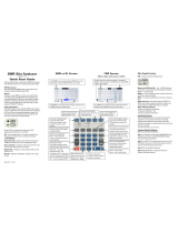
1.3 Layout and Controls
1. RF Connector: BNC-female. Use any SO-239-to-Male BNC
adapter when testing with PL-259 connectors (MFJ-7708 or
equivalent).
2. Rotary Encoder: Tunes DDS frequency when setting up
tests, positions marker when reviewing plot data, and scrolls for
some system set-up functions.
3. Encoder Control Switch: Selects tuning steps, and scrolls
through some setup menu choices.
4. Battery Status: Indicates battery power remaining, warns
when the battery is running low.
5. Elapsed Time: Displays running time for the current
operating session.
6. Function Key Labels: Displays the analyzer command-key
assignments (key assignments change for different operating
modes).
7. Membrane Function Keys: Enters command instructions
into the analyzer's processor.
8. POWER ON/OFF When powering off the Boot Screen must
be displayed.
1
2
3
4
00:15:32
7
5
6
8

MFJ-223 Vector Impedance Antenna Analyzer
MFJ Enterprises, Inc 5 Version 2
2.0 Power Source and Initial Setup
2.1 Charging the Battery: The MFJ-223 is powered by a
3.7-V 1930-mAH Lithium Polymer battery that comes pre-
installed. To recharge, use a micro-USB-to-standard-USB
patch cable (MFJ-5431 or equivalent). The analyzer can be
recharged from any standard computer USB slot capable of
delivering 5.0 volts at 500 mA. The analyzer's Micro-USB
charging jack is located on the bottom of the unit. Be sure to
charge the battery fully before turning on and operating your
analyzer for the first time.
To monitor the charge cycle, check the status LED located to
the left of the charging jack (LED not visible unless charging is
in progress). Red LED signals normal charging, Green LED
indicates when charging is complete, and Flashing LED warns
of a charging fault (battery or power-source problem).
During the charge, a built-in smart-controller monitors battery
condition and sets the best charge mode and rate. If the battery
is depleted below 2.9 volts, the charger supplies a 50-ma
trickle-charge until the 2.9-volt threshold is restored. It then
increases to a 500-ma constant-current rate until the level
reaches 4.2 volts. At that point, the controller switches into the
constant voltage mode and tapers the charge down to shutoff.
If your analyzer is being stored and not in regular use, recharge
it every 2-3 months to maintain battery health. Also, charge
fully before putting it away for extended periods.
Important Charging Note: Charge the battery before
operating your analyzer for the first time, before storing, and at
2-3 month intervals while in storage.

MFJ-223 Vector Impedance Antenna Analyzer
MFJ Enterprises, Inc 6 Version 2
2.2 Processor Reset: The MFJ-223 operating system is
immune to disruption from most glitches and EMP interference.
However, in the unlikely event of a system crash, you can reset
the processor by locating the small reset-switch access hole
located on the back right side of the case (about 1-inch down
from the top). To reset, insert the end of a paperclip or stiff wire
into the hole and press gently.
2.3 Turning Analyzer On and Off: To apply power, press
and hold the POWER Button down until you hear a sequence
of beeps, then release. This delay of about 3 seconds protects
against accidentally turning the analyzer on while in transit or
during routine handling. When the analyzer turns on, the Boot
Screen will appear on the display.
Use the same procedure to turn the analyzer off. Press and
hold the POWER Button down until you hear the beep
sequence, then release.
2.4 Enter Call Sign or Name: You may personalize your
analyzer by posting call letters or a name (up to eight
characters) on the Boot Screen. To program these in, power up
the analyzer and follow the procedure below:
Press the switch labeled System to bring up the
system menu.
Press Select to toggle between Auto-Off and Callsign.
Select Callsign.
Press the Encoder Knob to toggle the curser to the
start (or left) position.
Rotate the Encoder Knob to scroll in your first
character
Press the Encoder Knob to move to the second
character.
Continue building the sequence until your call or name
is entered.
Press Exit to return to the MFJ Boot Screen and view
your entry.
If you don't wish to enter a call or name, simply leave the field
blank. To remove an existing entry, overwrite with blank
spaces.
2.5 Auto-Off Function: The MFJ-223 has an optional
automatic-shutdown timer that conserves battery power during

MFJ-223 Vector Impedance Antenna Analyzer
MFJ Enterprises, Inc 7 Version 2
long activity lapses and prevents discharging the battery if the
analyzer is left on by mistake. Your data current remains in
memory when the analyzer shuts down, so nothing will be lost.
To activate (or to defeat) the Auto-Off function, use the
following procedure:
Press the key labeled System to bring up the System
Menu.
Press Select to toggle between Auto Off and Callsign.
Select Auto Off.
Rotate Encoder clockwise to activate it,
counterclockwise to deactivate it.
Press Exit to return to the Boot Screen.
2.6 System Screen: In addition to facilitating setup, the
System Screen posts other information such as the name and
revision of the current operating firmware, the text language,
reactance mode, and a battery DVM. It also counts the number
of times your analyzer has been booted since new (or since
reset).
2.7 Help Menu: To access the analyzer's eight-page Help
Menu, bring up the MFJ Boot Screen and use the following
procedure:
Press the Help key to bring up the Help-Contents page
Select a specific page using the S-Prev and S-Next
keys, then press Enter
Alternatively, press Enter then Next to scroll through all
8 pages sequentially
Press Top to return to page 1 or Exit to escape back to
the MFJ Boot Screen
2.8 Overload Precautions: Never connect your analyzer to
a feedline or device carrying a DC-bias voltage. If in doubt,
check the line with a voltmeter. Also, before connecting to
outdoor arrays, always short the coax plug momentarily to
discharge any accumulated static buildup. In addition to DC
and static discharge, high RF levels will also damage the
coupler. Never connect to a transceiver that could accidentally
transmit into the analyzer, and always check the interference
display when testing in high-RF areas. Disconnect immediately
if high pickup is indicated.

MFJ-223 Vector Impedance Antenna Analyzer
MFJ Enterprises, Inc 8 Version 2
Important Protection Warning: Never connect a DC voltage
or static-charged coaxial line to the analyzer.
3.0 DDS Frequency Entry
3.1 Tuning: The MFJ-223 tunes continuously from 0.5 to 60
MHz with a choice of five tuning rates. All selection is done
using the Encoder and Encoder Switch:
Rotary Encoder: Rotate the encoder knob to change frequency.
Each encoder indent shifts frequency by one tuning increment.
Use smaller increments for in-band tuning and larger
increments for rapid shifts or band changes.
Encoder Switch: Depress the encoder switch to scroll through
the five available tuning rates. They are: 100-Hz, 1-kHz, 10-
kHz, 100-kHz, and 1-MHz. A highlighted placeholder appears
below the analyzer's digital frequency display to designate the
selected increment (see below).
3.2 Rounding Off the Display: When you change the DDS
step size (or increment), the new step will be added to -- or
subtracted from -- the analyzer's current frequency setting. For
example, if the current frequency is 3.920 MHz and you select
a 1-MHz increment, rotating the encoder knob clockwise will
advance the frequency from 3.920 to 4.920 > 5.920 >
6.920...etc. in 1-MHz hops. As an alternative, you may choose
to round off the existing frequency before entering a new larger
increment. For example, you might tune from 3.920 up to 4.000
MHz first, and then switch to the 1-MHz step. Now the analyzer
will step from 4.000 to 5.000 > 6.000 > 7.000...etc. Rounding
off isn't mandatory, but some users find it helpful.
Fre 14.2500MHz
Step-Size Placeholder
V
Press to scroll
Step-Size
Rotate to
Change
Frequency
DDS Frequency Readout

MFJ-223 Vector Impedance Antenna Analyzer
MFJ Enterprises, Inc 9 Version 2
3.3 Practicing Entry: If DDS tuning is a new experience,
we recommend spending a few minutes practicing step-size
selection and frequency entry before heading out into the field
to make antenna measurements. Most users develop a feel for
DDS tuning quickly and enjoy its seamless mobility.
4.0 Single-Frequency Test Mode
4.1 Single-Frequency Screen Layout: In single-frequency
mode, pressing the Run/Stop key sends a steady CW carrier to
the antenna under test. The analyzer's directional coupler then
samples the incident (forward) and reflected (reverse) power
values and sends this data to the processor for conversion into
a visual display. The three top analog bars display approximate
SWR, Resistance (R) and Reactance (X). More precise
numerical values for SWR, R, X -- and also Impedance
Magnitude (Z) -- appear at the bottom of the screen (see
below).
With the generator running, you may change frequency on the
fly using the Encoder while watching the display for key points
of interest such as resonance (X = 0), minimum SWR, and the
antenna's 2:1 bandwidth limits. You may also use the analog
bars to provide continuous feedback when adjusting tunable
circuits or matching networks. Pressing Run/Stop again toggles
the generator off.
4.2 S-Antenna Bar: The S-Antenna bar warns when your
antenna is being energized by powerful external signals from a
nearby transmitter. It also indicates when the analyzer's DDS
generator is running, but its primary function is to detect
interference when the generator is stopped. A full-scale reading

MFJ-223 Vector Impedance Antenna Analyzer
MFJ Enterprises, Inc 10 Version 2
means power in excess of 0-dBm is being fed back into the
analyzer from an external source. In this event, disconnect the
analyzer immediately to avoid damaging the coupler. Although
marked in S-units, the meter is not logarithmic, so any reading
exceeding S2 or S3 could potentially interfere and cause
inaccurate readings.
Overload Warning: When testing, check the S-Antenna bar
with the generator turned off to see if disruptive RF levels are
being picked up by the antenna.
4.3 Single-Frequency Setup: To enter the Single-
Frequency mode from the Boot Screen:
Press the Single command key. The bar-graph
(labeled Single) will appear.
Connect the test antenna to the analyzer and check
the S-Antenna scale.
Use the Encoder to select a step and tune to your first
test frequency.
Press the Run/Stop key to start the DDS stimulus
generator running.
Tune as needed to explore the antenna's
measurements of interest.
Press the Run/Stop key again to terminate the test run.
The Run/Stop function conserves battery power, allowing the
analyzer to operate for extended periods without recharging.
4.4 DDS Signal Generator: The analyzer's test generator
may also be used as a highly accurate RF signal generator for
aligning receivers, tuning networks, or driving amplifier chains.
Typical output power level is +5 dBm (±1 dB) with 20-dB or
better harmonic suppression. Frequency resolution is 100 Hz
from 0.5 to 60.0 MHz with <5 ppm error. Anytime the analyzer
is in Single-Frequency mode and the Run/Stop key is
activated, a test signal will be generated. Note that the +5 dBm
power level may be too high for some sensitive preamplifier or
mixer stages and could damage them. The use of a wide-range
step attenuator is strongly recommended when using the
analyzer for any alignment procedure.
Important Signal Generating Warning: Avoid overdriving
sensitive circuitry with the analyzer's stimulus generator.

MFJ-223 Vector Impedance Antenna Analyzer
MFJ Enterprises, Inc 11 Version 2
5.0 Scan-Frequency Mode
5.1 Scan Overview: In Scan-Set mode, the DDS generator
steps rapidly across a preset range of frequencies and samples
reflected power at each stop. The scan's Center Frequency
and Tuning Step are entered the same way as they are for a
single-frequency test, via the Encoder. Along with Center
Frequency, you'll program in a Scan Width. Scan Width
determines the span of frequencies covered during the test. A
choice of eight scan widths are available, ranging from 300 Hz
to 48 MHz. Narrow scans are best for plotting low-frequency
mono-band antennas while wider scans are more useful for
broadband high-frequency antennas and multi-band arrays.
Each scan is initiated manually and takes roughly 3-5 seconds
to complete. When done, the analyzer switches from Scan-Set
mode to Present mode. In Present mode, four graphic plot files
are available for viewing (wave.SWR, wave.Z, wave.R, and
wave.X). Numerical data gathered at each sample frequency
can also be viewed using the analyzer's tunable marker
function to tune back and forth across the plot.
5.2 Screen Layout: Before going through the specific setup
instructions for conducting a test, take a moment to look over
the scan-mode screen's general layout. Being familiar with the
location and color-coding scheme for the various display
elements will help you to locate specific features more quickly.
To bring up the Scan-Set screen from the Boot Screen for
inspection, press the Scan command key. The screen is also
shown in the figure shown below:

MFJ-223 Vector Impedance Antenna Analyzer
MFJ Enterprises, Inc 12 Version 2
Top Line: The analyzer's current operating mode
(either Scan-Set or Present) appears between the
battery status and digital frequency display. Scan-Set
is used for setting up and initiating scans, while
Present is used to display results. In set-up mode, the
frequency display shows center frequency (CF), and in
presentation mode it shows the tunable-marker
frequency (MK).
Grid: This is the visual presentation area for plot files.
Note the calibrated measurement scale that appears to
the right of the grid.
First Line Under Screen: The Graph page (or wave-
file) designator shows which plot is currently selected
for display (SWR, Z, R, or X). The SPAN box next to it
shows the currently entered Scan-Width (this value can
be reset). VSPan shows the width used for the
previous scan (can't be reset). The Interference
Detector on the right side warns of strong interfering
signals (see 5.3).
Middle Line Under Screen: Displays numerical data
for SWR, Z, R, and X in Present mode. These fields
are normally blank in setup mode.
Bottom Line: Shows function labels for command
keys. Labels change for Scan-Set and Present modes
-- see specific instructions in 5.5 and 5.6.
5.3 Interference Detector: The cell-phone style signal bars
appearing in the lower right-hand corner of the screen warn of
potential RF interference. Like the S-Antenna bar, they show
deflection during scan runs, but the primary function is to warn
of high interference levels with the DDS scanner is turned off.
The scale is logarithmic with a range of -30 to +20-dBm (each
bar indicates a 10-dB increment). When more than one bar is
illuminated, interfering signals may be present. When three or
more bars are illuminated, disconnect the antenna line
immediately to protect the analyzer's coupler.
Signal Overload Warning: Before initiating scans, always
check the interference meter for powerful external signals.

MFJ-223 Vector Impedance Antenna Analyzer
MFJ Enterprises, Inc 13 Version 2
5.4 Scan-Set Entry Procedures:
In Scan-Set mode, the four function keys are assigned the
following functions:
[Return] Returns analyzer to the Boot Screen
[Present] Toggles the analyzer between Scan-Set and Present
mode
[Span] Scrolls to select scan width: (.3M, .6M, 1.2M, 2.4M, 6M,
12M, 24M, 48M)
[SCAN] Turns on DDS generator and initiates Scan
To enter from the Boot Screen, press Scan.
Choose a convenient Tuning Step using the Encoder
Switch.
Set your desired Center Frequency (CF) using the
Rotary Encoder.
Scroll with the SPAN key while watching the SPAN box
to select a scan width.
To initiate the scan, press the SCAN command key.
When you press Scan, the function label turns red while the
scan is in progress. Allow it to finish -- when complete, the label
turns back to green. Any previous scan data is overwritten by
the new scan data and the analyzer switches automatically
from Scan-Set to Present mode. Note that the Encoder
becomes assigned to the Marker (MK) function in Present
mode.

MFJ-223 Vector Impedance Antenna Analyzer
MFJ Enterprises, Inc 14 Version 2
5.5 Present Procedures:
In Present mode, the four command keys are assigned the
following functions:
[Return] Returns to the Boot Screen.
[Scan Set] Returns to Scan-Set so you may enter new setup
information.
[Graph] Scrolls through graphic plots for SWR, Z, R, and X
(wave. files).
[Scan] Initiates a re-scan using the current analyzer setup.
To view SWR, Z, R, and X plots in sequence, scroll
with the Graph key
To check numerical data at any scan-stop on any plot,
rotate Encoder
To return to Scan-Set mode to enter a new setup,
press ScanSet*
*After reviewing your plots, you may wish to expand or
compress them by using a wider or narrower scan width
(SCAN), or you may wish to move them left or right on the
screen by shifting and entering a new center frequency (CF).
Note the vertical scales change so they are not linear as seen
in the diagram. SWR changes at 1.2, 1.5, and 4. The
Resistance and reactance scales change at 100. This is to
allow the display of high numbers but still keep reasonable
resolution at low levels.

MFJ-223 Vector Impedance Antenna Analyzer
MFJ Enterprises, Inc 15 Version 2
5.6 Retrieving Data From Memory: The analyzer's
previous scan data remains in memory, even when the
analyzer is turned off. If you wish to recall it, do the following:
From the Boot Screen, press Scan. The analyzer
switches to Scan-Set mode.
From Scan-Set, press Present. The analyzer switches
to Present mode.
The marker function will be activated and your numerical data
will be recalled. To scroll through the screens, press Graph.
Note that the trace for your first plot (SWR) will not actually
appear on the screen until you cycle through Z, R, and X. If you
wish to set up a new test, press ScanSet and re-enter the
Scan-Set Mode. If you turn the analyzer off without initiating a
new scan, your old data will continue to be retained in memory.
6.0 Measurement and Accuracy Limitations
6.1 General: The MFJ-223 will serve as your eyes and ears
when working with RF systems. However, all handheld
analyzers share certain limitations, and being aware of them
will help you to achieve more meaningful results.
6.2 Local Interference: Like most hand-held units, this
analyzer uses a broadband directional coupler that is open to
receiving signals across the entire radio spectrum. Most of the
time, the unit's built in +5 dBm RF generator is powerful
enough to overcome the lack of front-end selectivity and
override stray pickup. However, a powerful transmitter located
nearby could inject enough RF energy through the antenna
under test to overload the directional coupler and disrupt
readings. If this condition occurs, performance may become
erratic and SWR readings may appear higher than they really
are.
6.3 Coupler Loss and Directivity: Simple broadband
couplers of the type used in the MFJ-223 may exhibit accuracy
limitations, especially at the higher end of the analyzer's
frequency range. Although accurate enough for amateur radio
applications, they typically lack the high degree of precision
and linearity needed for testing antennas and RF devices to
commercial or laboratory standards.

MFJ-223 Vector Impedance Antenna Analyzer
MFJ Enterprises, Inc 16 Version 2
6.4 Calibration Plane Error: The Calibration Plane is the
point of reference where all measurements have the greatest
accuracy (Gain Reference = 0dB and Phase Shift = 0 degrees).
For a basic handheld like the MFJ-223, the calibration plane is
fixed at the RF connector. Any time a transmission line is
installed, it displaces the load from the calibration plane and
introduces error. For SWR readings, the error is mainly caused
by loss in the cable (more loss means greater the error).
Generally, this condition isn't a problem because your radio
and the analyzer both see the same reduction in SWR.
However, if you're documenting antenna-SWR for design
purposes, the analyzer should be connected directly to the
feedpoint through a short pigtail to minimize error.
Calibration-plane error has far more significance for measuring
impedance because of phase rotation in the cable. In fact,
impedance readings may swing dramatically, depending on the
cable's electrical length and the severity of the load's mismatch
referenced to 50 Ohms. For meaningful impedance data,
always connect the analyzer directly to the DUT using the
shortest cable possible.
6.5 Reactance Sign Ambiguity: Most handheld analyzers,
including the MFJ-223, lack the processing capability to directly
calculate the reactance sign for complex impedance (Z = Rs
±j).

MFJ-223 Vector Impedance Antenna Analyzer
MFJ Enterprises, Inc 17 Version 2
7.0 In Case Of Difficulty: Note that the MFJ-223 has no
user-adjustable alignment controls. Opening the analyzer case
to perform unauthorized procedures could void your warranty.
If unit fails to operate properly, please check the suggestions
below before contacting MFJ for service or replacement.
Analyzer won't turn on: Battery may be fully
discharged. Plug in to charger, confirm red charge light
comes on, and check unit again after a couple hours.
Analyzer functions or display acts erratically:
Reboot the processor (see Chapter 2.2 for reboot
instructions).
All tests show very high or intermittently high
SWR: Check the condition of the analyzer's BNC jack
plus, any adaptors you may be using to transition to
the BNC jack, or condition of antenna connector and
coax.
If you are unable to resolve the problem, please follow the
specific procedures outlined in the Warranty section for further
assistance.

MFJ-223 Vector Impedance Antenna Analyzer
MFJ Enterprises, Inc 18 Version 2
8.0 Quick Start and Review of Analyzer
Functions:
Charging: Accepts micro-USB plug on base of unit.
Connect to USB port, charge until red LED turns green.
Charge fully before first use.
Turn On/Off: Press Encoder Knob down, wait for
beep, and release. Turn off the same way. Boot
Screen must be selected when turning off.
Commands from Boot Screen: Help opens help
index. System opens System page. Single opens
Single-Frequency test functions. Scan opens Scan-
Frequency set-up and presentation functions (see
chart above).
Help Menu Commands: Exit returns to Boot Screen.
S-Prev scrolls to previous page, S-next scrolls to next
page, Enter brings up highlighted page. Once a page is
selected, keys can scroll pages without returning to
index.
Frequency Control: Press Encoder Knob to select
tuning step (step size indicated by bar under frequency
display). Rotate Encoder Knob to change frequency.
RF Connector
Rotary Encoder and
control switch
Battery
Status
00:15:32
Function
Keys
Function
Key Labels
Power
Switch
/