Page is loading ...

© Inovonics, 2010 - www.inovonics.com, 2/23/10, P/N 7111855 Rev. E (05309C)
EN1261HT EchoStream® High Traffic Motion Detector
Installation Instructions - P/N 7111855 Rev. E (05309C), February
23, 2010
1 Overview
The EN1261HT is a wireless motion detector that features a detection range of 49 feet, fixed or
variable sleep time, a walk test feature, a front and rear tamper switch, and increased immunity to
radio frequency interference, vibration, static, lighting ambient temperature changes, and other
causes of false activation. The EN1261HT is supplied with a high capacity battery providing
extended battery life in high traffic environments, and designed with pet immunity up to 33 pounds
weight and 12” height.
Caution: The EN1261HT needs one minute for stabilization after power up. During the stabilization
period, the LED will blink twice per second, and the EN1261HT will not be operational.
Caution: Prior to operation, the EN1261HT must be acclimated to the temperature of the install
environment for a period of 60 minutes.
Note: Pet immunity has not been verified by UL and does not apply to UL installations.
Note: For UL installations, refer to the EN4216R Installation and Operation Manual or the EN7285
Installation Instructions.
1.1 Inovonics Wireless Contact Information
If you have any problems with this procedure, contact Inovonics Wireless technical services:
• E-mail: supp[email protected]
• Phone: (800) 782-2709; (303) 939-9336
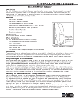
1.2 EN1261HT Components
Figure 1 EN1261HT components
2 Installation and Startup
2.1 Install/Replace Battery
To install the battery:
1. Release the housing screw and gently raise the cover.
Figure 2 Open the cover
2. Install the battery in the battery clip, ensuring the battery connector cable is on the same side as
the battery connector, shown as item J in Figure 1.
3. Plug the battery’s connector cable into the battery connector.
4. Press the Reset button to initialize the transmitter.
Note: You must press the Reset button each time the battery is changed.
2.2 Select the Frequency Band
EchoStream products are able to use a range of radio frequencies, and must be configured for your
geographic area. To configure the transmitter:
1. Place a selection jumper on the appropriate frequency band selection pins.
• Place the jumper on the left two pins, marked AU, to set the frequency range to 915-928 MHz
for Australia.
• Place the jumper on the right two pins, marked NZ, to set the frequency range to 921-928
MHz for New Zealand.
• Leave the jumper off the pins to set the frequency range to 902-928 MHz for North America.
Note: Only devices set for use in North America are configured for UL installations.
Note: Selection jumpers are included in the hardware bag.
2. Press the Reset button to initialize the transmitter.
Caution: When pressing the Reset button, make sure you don’t also touch the frequency band
selection pins. Touching the frequency band selection pins while pressing the Reset button can
inadvertently set the EN1261HT to the wrong frequency band.
2.3 Select Automatic/Pulse Count
The pulse count jumper setting provides control for normal or difficult operating environments.
Automatic pulse count is recommended for reliable operation in environments subject to temperature
fluctuations that may cause false alarms. The single pulse count mode is more sensitive to minor
temperature variations, and should be used in sites where variant heat sources will not cause false
alarms.
1. Place a selection jumper on the appropriate pulse count selection pins.
• Place the jumper on the left two pins, marked AUTO, to select automatic pulse count.
• Place the jumper on the right two pins, marked 1 PULSE, to select single pulse count.
2.4 Select Fixed/Variable Sleep Time
When set to variable, if the EN1261HT senses motion, it will transmit an alarm, then enter sleep
mode for the sleep time duration; if motion is sensed before the sleep time duration has expired, the
EN1261HT will restart the sleep time duration. Variable sleep time is the recommended, default
setting for high-traffic commercial environments.
Note: Variable is the default position.
When set to fixed, if the EN1261HT senses motion, it will transmit an alarm, then enter sleep mode
until the sleep time duration expires; if motion is sensed when the sleep time duration has expired,
the EN1261HT will transmit another alarm.
Note: The fixed setting is required for UL installations.
1. Place a selection jumper on the appropriate sleep count selection pins.
• Place the jumper on the right two pins, marked VAR, to select variable sleep time.
• Place the jumper on the left two pins, marked FIX, to select fixed sleep time.
2.5 Select Sleep Duration
If the sleep duration is set to maximum, the sleep duration will be 180 seconds. Maximum is the
recommended, default setting for most environments.
If the sleep duration is set to minimum and the sleep time is set to fixed, the EN1261HT will have a
sleep time of 15 seconds for the first six transmissions while motion is still sensed, followed by one
extended sleep period of 180 seconds. If the sleep duration is set to minimum and the sleep time is
set to variable, the EN1261HT will have a sleep time of 30 seconds.
Caution: EN1261HT motion detectors set in the minimum mode will have a decreased battery life.
1. Place a selection jumper on the appropriate sleep duration selection pins.
• Place the jumper on the left two pins, marked MAX, to select a maximum sleep duration.
• Place the jumper on the right two pins, marked MIN, to select a minimum sleep duration.
2.6 Using Sleep Time and Sleep Duration
Maximizing battery life To prolong battery life of the EN1261HT, select MAX on the sleep duration
pins, and VAR on the sleep time selection pins. With the variable sleep timer active and the sleep
duration set to maximum, the detector first sends an alarm and then sleeps for 180 seconds. If the
detector sees movement during this time, it restarts the sleep timer and doesn’t send an alarm. This
mode is recommended for high traffic environments with frequent activity during disarmed periods.
Increasing catch rate To maintain optimum detection immediately following system arming, select
MIN on the sleep duration pins, and FIX on the sleep time selection pins. When the detector sees
motion it goes to sleep for 15 seconds. If the detector sees movement during this time, and is still
active, it sends a new activation at the end of the 15 second window. The detector continues to do
this for five more cycles. After six consecutive cycles, the detector goes to sleep for an extended
180 second period to conserve batteries. Battery life may be significantly shortened by use of this
setting.
2.7 Adjust sensitivity
The sensitivity of the motion detector can be adjusted to fit your specific application. To adjust
sensitivity:
1. Use a philip’s head screwdriver to turn the sensitivity adjustment dial.
• Turn the dial to the left, towards the minus sign, to decrease the motion detector’s sensitivity.
• Turn the dial to the right, towards the plus sign, to increase the motion detector’s sensitivity.
2.8 Register the Transmitter
The EN1261HT must be registered with the system receiver in order to be monitored and
supervised. Each EN1261HT has a unique factory-programmed identification number.
Note: The transmitter’s unique identification number is the eight digit serial number found on the
serial number label.
Refer to the receiver installation instructions for details on registering a transmitter.
1. When prompted, press the Reset button.
2. Replace the EN1261HT cover.
3. Replace the housing screw.
Caution: The EN1261HT should be tested after registration to ensure operation. To test the
EN1261HT, activate each of the conditions and ensure an appropriate response.
Note: The EN1261HT retains programming data in non-volatile memory. It does not require re-
programming after loss of power.
A Frequency band selection pins B Reset button C Pulse count selection pins
D Tamper switch E Test mode reed switch F Sleep time selection pins
G Sleep duration selection pins H Sensitivity adjustment dial I Battery clip
J Battery connector
C
A
D
B
E
F
H
G
J
I
Housing
screw

© Inovonics, 2010 - www.inovonics.com, 2/23/10, P/N 7111855 Rev. E (05309C) 2
2.9 Mount the Transmitter
Mount the transmitter.
1. Remove the EN1261HT printed circuit board from the housing.
2. Use the included hardware to mount the EN1261HT housing back plate to the mounting
surface.
a. If using the wall tamper function for increased security, mount the housing back plate per
Figure 3, ensuring the tamper switch is depressed.
Note: The wall tamper switch must be used for UL installations.
Figure 3 EN1261HT mounting back plate
b. If not using the wall tamper, mount the housing back plate using all appropriate hardware.
2.1 Mounting Considerations
The following should be considered when mounting the EN1261HT:
• The motion detector should be mounted such that the expected intrusion motion is
perpendicular to the protection zones
• The motion detector may not detect motion behind obstructions, including blinds, curtains,
and drapes
• The motion detector should be mounted on a solid, vibration-free mounting surface
• Fans and blowers can cause false alarms.
• The following may cause false alarms:
- Fans
- Blowers
- Drafts
- Windows
- Heat and cooling sources
- Sunlight
- Animals
The EN1261HT is intended to be installed in accordance with the following:
• The local authority having jurisdiction
• The National Electrical Code, ANSI/NFPA 70
• The Canadian Electrical Code
• The Standard for Installation and Classification of Burglar and Holdup Alarm Systems, UL 681
• The Standard for the Installation and Classification of Residential Burglar Alarm Systems,
CAN/ULC-S310
• The Standard for Central-Station Alarm Services, UL 827
• For certified proprietary burglar alarm installations, the requirements of UL 1076, Proprietary
Burglar Alarm Units and Systems, also applies
2.2 Optional Ceiling/Wall Mount Application
Note: Not to be used for UL installations.
The optional ceiling and wall mount brackets are available separately from Inovonics, part number
ACC665.
Note: Applications that require the back tamper cannot use the ceiling or wall mount bracket.
Figure 4 Ceiling and wall mount brackets
To mount a ceiling or wall bracket:
1. Remove the pcb board.
2. Attach the housing to the bracket.
Figure 5 Remove the pcb board and attach the housing to the bracket
3. Replace the pcb board.
3 Test the EN1261HT
Caution: The EN1261HT should be tested after registration, and at least once a year thereafter, to
ensure operation. To test the EN1261HT, activate each of the conditions and ensure an appropriate
response.
3.1 Perform a Walk Test
The walk test is performed to ensure motion is sensed and an RF transmission results. To perform a
walk test:
1. Swipe the magnet past the reed switch. The five minute walk test will begin; every time motion
is sensed, the LED will light and the EN1261HT will transmit a signal.
2. Walk in front of the motion detector to test the sensor.
3. After five minutes the walk test will automatically end.
4 Operation
The EN1261HT transmitter signals an alarm condition when motion is detected by the sensor.
Figure 6 Standard mounting height and range
5 Specifications
Dimensions: 4.5”H x 2.5”Wx 1.6”D (11.4 cm x 6.4 cm x 4.1 cm)
Detection method: Quad element PIR
Storage temperature: -4° to 140°F (-20° to 60°C)
Operating temperature: 32° to 122°F (0° to 50°C)
Humidity: 0 - 93% (non-condensing)
Battery: 3V, 2.2Ah battery, BAT610
Power requirement: 3VDC, 60 mA
Temperature compensation: Yes
Tamper: Housing and wall tamper
PIR RF interference immunity: Greater than 30 v/m 26 MHz - 1 GHz
Stabilization period: One minute
Alarm lockout time: Three minutes (in fixed, maximum mode)
Walk test period: five minutes
Mounting height: 6’ 10” to 8’ 10” (2.1 to 2.7m)
UL listings UL 365, UL 639, UL 1023, ULC/ORD-C1023-74, ULC-S306, UL1076, UL 1610
Compatible UL receiver: EN4216R, EN7285
Compatible UL repeater: EN5040-T
FCC ID: HCQ3B6OTCWP
IC ID: 2309A-OTCWP
6 Warranty/Disclaimer
Note: Changes or modifications to this unit not expressly approved by Inovonics may void the
installer's authority to operate the equipment as well as the product warranty.
Inovonics Wireless Corporation ("Inovonics") warrants its EchoStream products ("Product" or
"Products") to conform to its own specifications and to be free of defects in materials and
workmanship under normal use for a period of thirty-six (36) months from the date of manufacture.
Within the warranty period, Inovonics will repair or replace, at its option, all or any part of the
warranted Product. Inovonics will not be responsible for dismantling and/or reinstallation charges. To
exercise the warranty, the User ("User", "Installer" or "Consumer") must work directly through their
authorized distributor who will be given a Return Material Authorization ("RMA") number by
Inovonics. Details of shipment will be arranged directly through the authorized distributor.
This warranty is void in cases of improper installation, misuse, failure to follow installation and
operating instructions, alteration, accident or tampering, and repair by anyone other than Inovonics.
This warranty is exclusive and expressly in lieu of all other warranties, obligations or liabilities,
whether written, oral, express, or implied. There is no warranty by Inovonics that Inovonics product
will be merchantable or fit for any particular purpose, nor is there any other warranty, expressed or
implied, except as such is expressly set forth herein. In no event shall Inovonics be liable for an
incidental, consequential, indirect, special, or exemplary damages, including but not limited to loss of
profit, revenue, or contract, loss of use, cost of down time, or interruption of business, nor any claim
made by distributor's customers or any other person or entity.
This warranty will not be modified or extended. Inovonics does not authorize any person to act on its
behalf to modify or extend this warranty.
This warranty will apply only to Inovonics Products. Inovonics will not be liable for any direct,
incidental, or consequential damage or loss whatsoever, caused by the malfunction of Product due
to products, accessories, or attachments of other manufacturers, including batteries, used in
conjunction with Inovonics Products.
Mount either
corner or wall with
screw only
Mount either
corner or wall
with screw and
wall anchor
Mount either corner
or wall with screw
only
Ceiling mount
installation
Wall mount
installation
6’ 10”- 8’ 10”
49’
Up to a 1' (0.3 m)
dead zone will
occur
/