Setting on sensitivity pulse
3 puls es
(low s en sitiv e)
2 puls es
(hig h se nsiti vity)
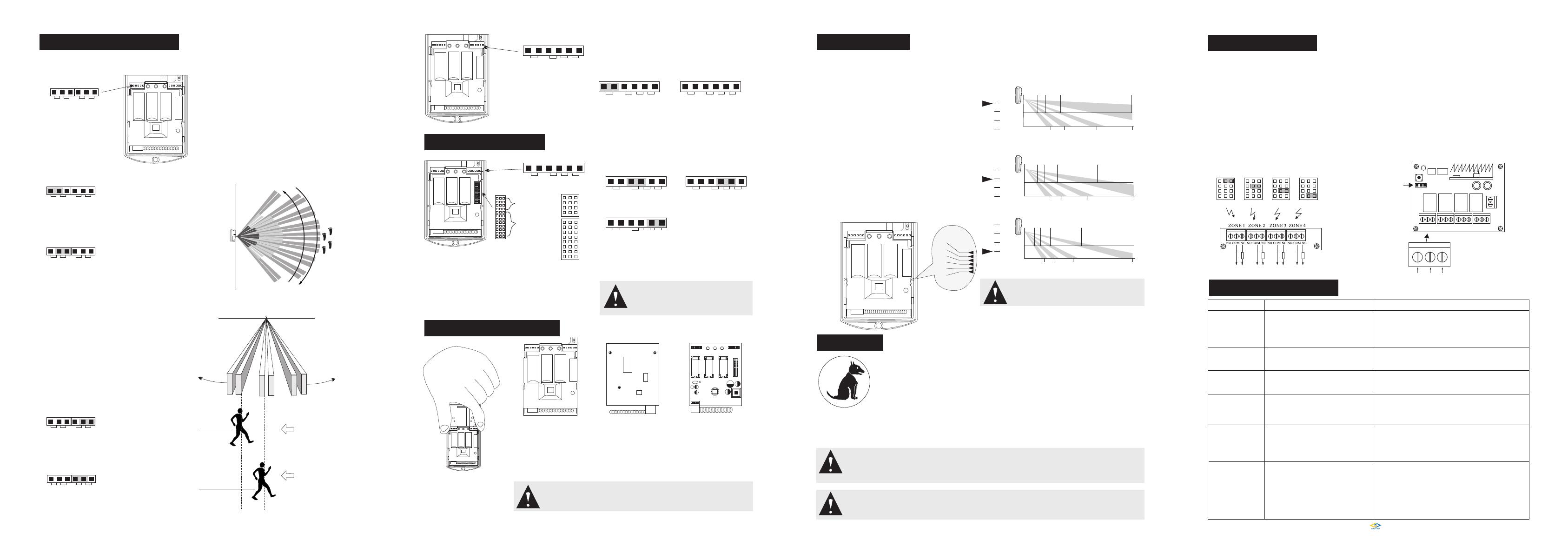
Detector can get its best detection by setting of PCB
vertical height, strongly suggest installer should make
optimum setting to PCB vertical height according to actual
environment.
Mark-1: when PCB is set to this position, detector is with
best pet immunity.
Mark 0: when PCB is set to this position, detector is at most
standard status.
Mark1: when PCB is set to this position, detector can avoid
ambitious crawl intrusion; mean while, pet immunity
function will be lowered.
Mark 2,3,4: when installation height is over 2.4m, in order
to get best cover range, please move PCB unit
to mark 4 position and make actual walking test
to confirm actual detection range till complete
protection requirements are reached.
12.Vertical adjustment
2.1 3.1 5.9 15
3.9 6 10.4 15
2.1m
4m
1.8 2.7 4.8 13
3.4 5.2 8.7 15
2.1m
4m
1.5 2.3 3.7 8
2.9 4.4 715
2.1m
4m
Effect chart on wide angle lens adjustment
9.Different settings & walking test
TEST/USE mode switch
When jumper is set to TEST
mode , detector can be
triggered any time.
When jumper is set to USE
mode , detector can be
triggered for 4 minutes
interval time for the purpose
of battery energy save, this
is recommended mode.
TEST mode
(costly status)
USE TEST
Mode pulse
3P 2P
USE TEST 3P 2P
USE TEST 3P 2P
USE mode
(economical)
When jumper is set to 3P,
detector is set to low sensitivity,
alarm will be triggered when
more than 3 pulses are detected.
USE TEST 3P 2P
When jumper is set to 2P,
detector is set to high sensitivity,
alarm will be triggered when
2 pulses are detected
USE TEST 3P 2P
walking test
123456
Fast detection on target
Excellent way to avoid false alarm
Signal process statement: this detector adopts direct
analysis technology on digital signal, microchip
will make analysis on frequency/range/polarity
etc of detected signals and make comparison with
frequent pets data in data base, after that, it will
draw a real intrusion analysis and judgment. Here,
pulse set is a general index for reference, it doesn't't
stand exact quantity of pulse during digital signal
process.
4.7M 3.3M 1.5M
LED Oscillation
resistance When jumper is set to OFF mode, LED will not
light even alarm is triggered, it is for the purpose
of conceal and energy-save. (Recommended way)
ON
(LED ON)
OFF
(LED OFF)
Alarm LED control
4.7M 3.3M 1.5M
LED
4.7M 3.3M 1.5M
LED
10. FROM WIRELESS TO WIRED
Parameter corresponding with other control panels can
be reached by setting of oxcillation resistance on coding
chips. Please refer to below figure, we h ave 3 modes:
4.7M/3.3M/1.5M
Different address ID can be obtained by setting on 8
jumpers on “ADD SET”?for the purpose of recognition
by control panel.
Setting of data jumper
Setting of address codes
ADD SET A7
A6
A5
A4
A3
A2
A1
A0
D3
D2
D1
D0
DATA SET
oscillation resistance setup
L H
H=high level
L=low level
4.7M 3.3M 1.5M
LED
4.7M
LED
3.3M
LED
1.5M
LED
11.Low voltage and battery change
EVE
EVE
EVE
1.Move down PCB unit as figure
2.Loose down 3 screws as figure 3.Batteries can be changed now
This detector can support 3 of 1/2 AA batteries, if 3 of batteries are used together,
detector can work for more than 24 months in USE mode.
Note: if 2 or 3 batteries have been working together, when need to change
batteries, please change them in all and try to avoid mixed operation
between new and old batteries.
1
0
-1
-2
-3
-4
-1
0
1
2
-1
0
1
2
-1
0
1
2
13.Pet immunity
Pet immunity is a high index for judgment of PIR detector function, we adopt 2 methods on pet
Immunity process at the same time:
1.Physical method: special process of Fresnel lens detection area to lower false alarm rate caused
by small animals
2.Software analysis method: analysis on technical data on detector signal and make comparison
with data base in the microchip in detector, then draw a conclusion on moving object to verify
it is human being or pets.
From above we can know that function of pet immunity is relevant, this relativity includes 2 parts: firstly, pet immunity
is relevant, but its false alarm rate is greatly lowered comparing detectors without pet immunity function, at the same
time, there is limitation on pets' quantity and size. Secondly, installation is very important to pet immunity, it is with
some requirements, not a random installation can reach a good result, so please read details in the manual before
installation.
Note: if multi-directional bracket is used,
detection range will be different from description
above.
Note: we can omit those animals below 1m or 20kg on ground, but as pets approaching detector, its moving
frequency will change, and pet immune function will be weakened, so a reasonable position is strongly
suggested to be selected to avoid pets' approaching.
Note: when pet immunity function is required while multi-directional bracket is used, detector should be
vertical to wall, no leaning. And bracket adjustment is allowed in horizontal direction, detector should be
installed vertically to ground!
15. Common touble and solutions
Trouble Possible reasons Solution
Power LED doesn't light
1.Battery low voltage(below 3.2V)
2. Poor contact between battery clip and battery
3.Reversed battery installation
4.Don't switch on LED control
5.May in USE mode
1.Check battery voltage and change new battery
2.Re-install battery or polish contact
3.Make correct installtion
4.Turn on LED during test
5.Select TEST mode
When battery voltage is lower than 2.85V, detector will send out low voltage alarm
signal, then LED will flash for 5 times continuously. If detector gets continuous signal
from battery low voltage, it will send alarm signal to control panel every 60 minutes
for purpose of recommendation to user on battery change.
Detection distance
less than 12m
False alarm
Short wireless distance
Not compatible with
control panel
Short battery life
1.Re-adjust installation height (1.8-2.4m)
2.Adjust installation angle
3.Adjust PCB unit vertical position
1.Poor battery quality
2.Detector not in USE mode
3.Alarm LED not turn off
1.Change high quality battery( Use factory battery or brand-named battery
2.Set jumper to USE mode
3.Turn off alarm LED to save energy
1.Different protocol
2.Improper resistance
3.Wrong data set
4.Some address jumpers can't be empty
1.Select proper codes and protocol
2.Select proper resistance
3.Select proper data set
4.Set address pin to H or L
Contol panel can’t receive alarm signai from
detector after alarm is triggered.
1.Change detector position
2.Pull out antenna on contorl panel to longest position
3.Select high sensitivity control panel
4.Add a repeater
5.Environment is not suitable for wireless control panel installation
1.Periodical alarm, 1 alarm each 60 minutes
2.Tamper switch alarm
3.Strong interference nearby
4.Pets' height and weight more than detection limitation
5. Sunsport activity period
6.Operation temperature over limitation
7.Water goes into detector
8.Strong environment interference
1.Low batter voltage, change it
2.Reset tamper switch
3.Keep detector away from strong interference
4.Pay attention to big animal's intrusion
5.No need to handle, it will resume after sunspot passes
6.Operation in recommended environment
7.Pay attention to water proof, add O shape water proof rubber ring
8.Set sensitivity to 3P
Ver. 201415.01
Power:DC 12V
Power consumption:6mA
Receiving sensitivity: over 105dBm
Frequency:315M/433M for option
Output capacity:1A
Size:72mm*52mm*26mm
Main specifications
14. Wireless to wired device
This intelligent wireless receiver with 4 channels is with
4 relays and can control the open/close conversion of
switch and various kinds of special control procedures.
This unit is with the characteristics of stable performance,
small size and high receiving sensitivity etc, can be used in
intrusion ala r m to rea ch the conversion from wired to
wireless system.
BRIEF INTRODUCTION
Study/delete way and steps
1.Press down “STUDY” key, the indicator will
turn on, then leave go off, trigger detector and
LED gives 2 flashes and turn off, study is successful.
2. Delete: keep pressing down the STUDY (the
black knob) key for 8 seconds, indication will
turn off then all messages are deleted successfully.
NO COMM NC
ZONE OUTPUT
4 zones output
Lear nin g button
NO COM NC NO CO M NC NO COM N C NO COM N C
ZONE 1 ZONE 2 ZONE 3 ZONE 4
J1 J2
Relay
How can wireless detectors be connected to
wired contorl panel?
EOL resistor mube be connected !
Wireless to
wired module
L H L H L
D3
D2
D1
D0
D3
D2
D1
D0
D3
D2
D1
D0
L H
D3
D2
D1
D0
To wired zone on control panel
H
D C 1 2 V
Note: some control panel doesn't allow
data jumper to be empty, should be set
to high or low level, if not, control panel
can't distinguish the codes.
Mode pulse
Mode pulse
pulse
Mode
Mode pulse
Oscillation
resistance Oscillation
resistance
1.Improper installation height
2.Improper installation angle
3.PCB not in best position
Set detector to TEST mode and turn on LED, close well the
front cover and wait for LED OFF. Make horizontal movement
in detection area and watch the PIR detection status on LED
(when alarm i s trig gered L ED w il l f la s h f or 2 t i mes
continuously). This is to confirm that there is no blind angle
for PIR in the protection spot. When intruder makes horizontal
movement towards detector, sensitivity is the highest!
When detector is installed in different environments, please
adjust PIR sensitivity and detection pulse properly. There
are 2 grades for sensitivity: high and l ow. When pulse is
set to 2, detector is with high sensitivity; when 3 pulse is
set, detector is in low sensitivity. Normal settingg is 2 pulse.
Installer can turn off or turn on alarm LED according to
actual needs after the test.
Strongly suggested: please select “USE” mode AND
“LED OFF”set in order to keep battery working longer. Oscillation
resistance
Oscillation
resistance
Oscillation
resistance
Oscillation
resistance
PIR A PIR B PIR C PIR D
Jumpers are not
needed here!
Power input
Relay Relay Relay
This control unit is compatible with wireless remote control
and wireless detector with various kinds of micro chips
or multiple codes, and protocols can be 2262/2260/1527/2240.
Proper coding data for can be obtained by jumper setting
on “DATA SET”,then control panel can recognize the
codes:D3/D2/D1/D0.
SUNLIT TECHNOLOGY(HK) CO.,LTD


