Mircom LT-535 FA102U Operating instructions
- Category
- Fire protection
- Type
- Operating instructions
Mircom LT-535 FA102U is a supervised 2 zone 24VDC Fire Alarm Control Panel. It provides the following features:
- 2 class B detection zones
- 1 class B signal zone, 1.25A
- Alarm and trouble relay contacts
- Remote trouble and A.C. ON indication
- Individual zone silence/disconnect switches
- Trouble silence switch
- Subsequent alarm operation
- LED indicators for zone Alarm and Trouble, A.C. On, Battery Fault, Ground Fault, Common Trouble, Signal Trouble and Signal Silenced The device can be used in various applications, such as:
- Homes
- Offices
- Schools
- Hospitals
- Commercial buildings
- Industrial facilities

LNOTICE
All information, documentation, and specifications contained in this manual are subject
to change without prior notice by the manufacturer.
®
FA-102U
Fire Alarm Control Panel
INSTALLATION and OPERATION MANUAL
©1998 by Mircom Technologies Limited
Printed in CANADA, Dec 2005
LT-535 Rev. 4


MODEL FA-102U
FIRE ALARM CONTROL PANEL
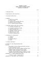
TABLE OF CONTENTS
PAGE
1. INTRODUCTION . ................................. 1
2. MECHANICAL INSTALLATION . ......................... 1
3.FUNCTIONSELECTION .............................. 1
4. WIRING:
4.1 DETECTION ZONES ............................ 2
4.2 SIGNAL ZONE . . . ............................ 2
4.3ALARMANDTROUBLERELAYS ................... 2
4.4 REMOTE ANNUNCIATION ........................ 2
4.5 A.C. POWER AND BATTERIES ..................... 2
5. TROUBLE INDICATORS AND CONTROL:
5.1COMMONTROUBLELED ........................ 2
5.2COMMONTROUBLEBUZZER ..................... 2
5.3ZONETROUBLELED........................... 2
5.4TROUBLESILENCESWITCH ...................... 2
5.5 BATTERY FAULT LED .......................... 3
5.6 GROUND FAULT LED .......................... 3
5.7 SIGNAL TROUBLE LED ......................... 3
6. SEQUENCE OF OPERATION:
6.1NORMAL .................................. 3
6.2ALARM ................................... 3
6.3 SIGNAL SILENCE ............................. 3
6.4RESET.................................... 3
7. SYSTEM CHECKOUT ................................ 4
8. POWER UP AND TROUBLESHOOTING ..................... 4
FIGURES:
1. BACKBOX & FLUSH TRIM MOUNTING DETAILS .......... 5
2. CIRCUIT BOARD LAYOUT . . . ....... .............. 6
3. DETECTION AND SIGNAL WIRING INSTRUCTION ......... 7
4. WIRING TABLE FOR DETECTION ZONES ............... 8
5.WIRINGTABLEFORBELLSANDHORNS............... 9
6. ALARM AND TROUBLE RELAY CONTACTS, AND
REMOTE ANNUNCIATION WIRING INSTRUCTION ......... 10
APPENDIX “A” 2-WIRE SMOKE DETECTOR
CONTROLPANELCOMPATIBILITY................... 11
APPENDIX “B” BATTERY CALCULATIONS .................... 14


-1-
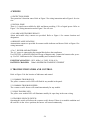
1. INTRODUCTION
The FA-102U is a supervised 2 zone 24VDC Fire Alarm Control Panel.
The panel provides the following features:
- 2 class B detection zones
- 1 class B signal zone, 1.25A
- Alarm and trouble relay contacts
- Remote trouble and A.C. ON indication
- Individual zone silence/disconnect switches
- Trouble silence switch
- Subsequent alarm operation
- LED indicators for zone Alarm and Trouble, A.C. On, Battery Fault, Ground Fault,
Common Trouble, Signal Trouble and Signal Silenced
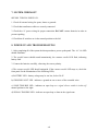
2. MECHANICAL INSTALLATION
The panel can be surface or flush mounted. Refer to Figure 1 for dimensions.
For surface mounting, mark the location of the four mounting holes. Install the top two screws into
the wall and place the panel over the screws. Install the bottom screws, and tighten down all four
screws.
For flush mounting, make the wall cut-out according to the panel dimensions. Remove the control
panel door. Mount the flush mounting trim (MODEL FA-102TRU) to the back box using the screws
and nuts provided with the flush mounting kit. Re-install the door on top of the flush trim. The cam
lock may require a minor adjustment in order to compensate for the flush trim.
3. FUNCTION SELECTION
The following jumpers are available for function selection, refer to Figure 2 for location;
JW1 Cut for normally open trouble contacts.
JW2 Cut for normally closed trouble contacts.
JW3 Cut to enable common alarm relay to de-energize if signal silence switch is activated.
JW6 Cut if 60 second signal silence inhibit is not required (Signals can be manually
silenced any time if cut).

-2-
4. WIRING
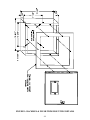
4.1 DETECTION ZONES
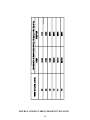
The system has 2 detection zones. Refer to Figure 3 for wiring instruction and to Figure 4 for wire
size.
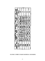
4.2 SIGNAL ZONE
There is 1 signal zone available for bells and horns providing 1.25A of signal power. Refer to
Figure 3 for wiring instruction and to Figure 5 for wire size.
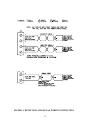
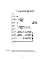
4.3 ALARM AND TROUBLE RELAYS
Alarm and trouble relay contacts are provided. Refer to Figure 6 for contact location and
designation.
4.4 REMOTE ANNUNCIATION
Annunciation outputs are provided for remote trouble indicator and buzzer. Refer to Figure 6 for
wiring instruction.
4.5 A.C. POWER AND BATTERIES
The A.C. power is connected to the terminal block above the transformer.
Use GEL CELL or SEALED LEAD-ACID type of batteries only. Connect the batteries after power
up. Use 24V 4AH batteries for 24 hours standby and 5 minutes of alarm.
ELECTRICAL RATING: 120V, 60Hz, 1A / 240V, 50 Hz, 0.5A
BATTERY CHARGER: 200mA MAXIMUM CHARGING CURRENT
5. TROUBLE INDICATORS AND CONTROL
Refer to Figure 2 for the location of indicators and control.
5.1 COMMON TROUBLE LED
The yellow common trouble LED will flash for any trouble in the panel.
5.2 COMMON TROUBLE BUZZER
The common trouble buzzer will sound intermittently for any trouble.
5.3 ZONE TROUBLE LED
The yellow zone trouble LED will illuminate steadily for open loop in the zone wiring.
5.4 TROUBLE SILENCE SWITCH
Operating this switch will silence the common trouble buzzer. If there is no trouble condition and
the switch is in the silence position, the buzzer will sound continuously.

-3-
5.5 BATTERY FAULT LED
Battery removal, low voltage and open battery leads will turn on the yellow battery fault LED and
the common trouble LED.
5.6 GROUND FAULT LED
Any ground fault of 10K ohms or less will turn on the yellow ground fault LED steadily, flashing
the common trouble LED and sounding the common trouble buzzer intermittently.
5.7 SIGNAL TROUBLE LED
The yellow signal trouble LED will illuminate steadily for any open or short.
(The LED is located behind the display plate.)
6. SEQUENCE OF OPERATION
Refer to Figure 2 for the location of indicators and controls.
6.1 NORMAL
All indicators are normally OFF except for the green A.C. On LED.
6.2 ALARM
A red zone alarm LED will illuminate steadily for incoming alarm.
6.3 SIGNAL SILENCE
If the 60 second signal silence inhibit is selected, the signals cannot be silenced for 60 seconds
after the first alarm initiation. Once the 60 seconds have expired, pushing the signal silence
switch, which correspond to the zone in alarm, to the right will silence all the bells and horns.
An alarm on the other zone will resound the signals (subsequent alarm). Pushing the other signal
silence switch to the right, after a subsequent alarm will silence the panel. Once the signals have
been silenced, the signal silenced LED will illuminate. If the switches are in the off normal
position to the right while there is no alarm condition, the panel will indicate trouble.
6.4 RESET
Operating the reset switch will restore all latched functions in the panel. The smoke detectors will
reset if all products of combustion are cleared from their chambers.

-4-
7. SYSTEM CHECKOUT
BEFORE TURNING POWER ON:
1. Check all external wiring for opens, shorts or grounds.
2. Check that transformer cables are securely connected.
3. Check the A.C. power wiring for proper connection. DO NOT connect batteries in order to
prevent sparking.
4. Check that all switches are in the normal position to the left.
8. POWER UP AND TROUBLESHOOTING
1. After completing all of the system checkout procedures, power up the panel. The A.C. On LED
should illuminate.
2. The trouble buzzer should sound intermittently, the common trouble LED flash, indicating
battery fault.
3. Connect the batteries carefully, observing the correct polarity.
4. The common trouble LED should extinguish. If the common trouble LED stays on, check the
front panel for the illumination of the following LEDs;
a) BATTERY LED - battery voltage may be too low, below 20.4V.
b) GROUND FAULT LED - indicates a ground on one or more of the extended wires.
c) ZONE TROUBLE LED - indicates an open loop or a signal silence switchisintheoff
normal position to the right.
d) SIGNAL TROUBLE LED - indicates an open loop or short in the signal zone.

-5-
FIGURE 1: BACKBOX & FLUSH TRIM MOUNTING DETAILS

-6-
FIGURE 2: CIRCUIT BOARD LAYOUT

-7-
FIGURE 3: DETECTION AND SIGNAL WIRING INSTRUCTION

-8-
FIGURE 4: WIRING TABLE FOR DETECTION ZONE

-9-
FIGURE 5: WIRING TABLE FOR BELLS AND HORNS

-10-
FIGURE 6: ALARM AND TROUBLE RELAY CONTACTS AND
REMOTE ANNUNCIATION WIRING INSTRUCTIONS

-11-
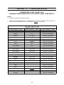
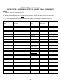
APPENDIX "A" - COMPATIBLE DEVICES
UNDERWRITER’S LABS CANADA (ULC)
CANADIAN 2-WIRE SMOKE DETECTOR CONTROL PANEL COMPATIBILITY
NOTES:
1.* Reset time, hold for five seconds minimum.
2. Whether mixing different models of compatible smoke detectors, or using the same model on the
same Circuit, total standby current of all detectors must
not exceed 3 mA.
SMOKE DETECTOR
MAKE MODEL / BASE MAKE MODEL / BASE MAKE MODEL / BASE
MIRCOM CERBERUS PYROTRONICS FENWAL
MIR-525 D1-2 PSD-7131 / 70-201000-001
MIR-525T D1-3 / DB-3S PSD-7131 / 70-201000-002
PSD-7131 / 70-201000-003
SYSTEM
SENSOR
PSD-7131 / 70-201000-005
1400-A PSD-7130 / 70-201000-001
MIRTONE
2400-A 73471 PSD-7130 / 70-201000-002
1451-A / B401B 73494 PSD-7130 / 70-201000-003
1451-A / B406B 73575 PSD-7130 / 70-201000-005
2451-A / B401B 73495 / 73486 PSD-7128 / 70-201000-001
2451-A / B406B 73495 / 73487 PSD-7126 / 70-201000-002
1451DH / DH400A 73595 / 73486 PSD-7126 / 70-201000-003
2451-A / DH400A 73595 / 73497 PSD-7126 / 70-201000-005
EDWARDS
73594 / 73400 PSD-7129 / 70-211002-000
6249C 73405 / 73400 PSD-7125 / 70-201000-001
6250C 73594 / 73401 PSD-7126 / 70-201000-002
6264C 73405 / 73401 PSD-7125 / 70-201000-003
6266C PSD-7125 / 70-201000-005
6269C CPD-7021 / 70-201000-001
6270C CPD-7021 / 70-201000-002
SIMPLEX
6269C-003 2098-9110 CPD-7021 / 70-201000-003
6270C-003 CPD-7021 / 70-201000-005

-12-
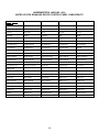
UNDERWRITER’S LABS INC. (ULI)
UNITED STATES 2-WIRE SMOKE DETECTOR CONTROL PANEL COMPATIBILITY
NOTES:
1. Reset time, hold for five seconds minimum.
2. Whether mixing different models of compatible smoke detectors, or using the same model on the same Circuit,
total standby current of all detectors must
not exceed 3 mA.
3. The below listed Smoke Detectors are compatible with Initiating Circuits having Compatability Identifier "A".
SMOKE DETECTOR COMPATIBILITY RATED STANDBY SMOKE DETECTOR COMPATIBILITY RATED STANDBY
MAKE MODEL / IDENTIFIER CURRENT MAKE MODEL / IDENTIFIER CURRENT
BASE HEAD / BASE BASE HEAD / BASE
SYSTEM
SENSOR SENTROL - ESL
1100 A - N/A 0.12 mA 429C S10A - N/A 0.10 mA
1151 / B110LP A - A 0.12 mA 429CT S10A - N/A 0.10 mA
1151 / B116LP A - A 0.12 mA 429CST S11A - N/A 0.10 mA
1400 A - N/A 0.10 mA 429CRT S11A - N/A 0.10 mA
1451 / B401 A - A 0.12 mA 711U / 701E, 701U, S10A - S00 0.10 mA
702E, 702U
1451 / B401B A - A 0.12 mA 712U / 701E, 701U, S10A - S00 0.10 mA
702E, 702U
1451 / B406B A - A 0.12 mA 713-5U / 701E, S10A - S00 0.10 mA
701U, 702E, 702U
1451DH / DH400 A - A 0.12 mA 713-6U / 701E, S10A - S00 0.10 mA
701U, 702E, 702U
2100 A - N/A 0.12 mA 721U / 702E, 702U S10A - S00 0.10 mA
2100T A - N/A 0.12 mA 721UT / 702E, 702U S10A - S00 0.10 mA
2151 / B110LP A - A 0.12 mA 722U / 702E, 702U S10A - S00 0.10 mA
2151 / B116LP A - A 0.12 mA 731U / 702E, 702U, S11A - S00 0.10 mA
702RE, 702RU
2400 A - N/A 0.12 mA 732U / 702E, 702U, S11A - S00 0.10 mA
702RE, 702RU
2400TH A - N/A 0.12 mA
2400AT A - N/A 0.12 mA
DETECTION
SYSTEMS INC.
2400AIT A - N/A 0.12 mA DS250 B - N/A 0.10 mA
2451 / B401B A - A 0.12 mA DS250TH B - N/A 0.10 mA
2451 / B406B A - A 0.12 mA DS282 B - N/A 0.10 mA
2451 / DH400 A - N/A 0.12 mA DS282TH B - N/A 0.10 mA
2451TH / B401B A - A 0.12 mA
2451TH / B406B A - A 0.12 mA
2451 / B401 A - A 0.12 mA
2451TH / B401 A - A 0.12 mA
4451HT / B401B A - A 0.12 mA
4451HT / B406B A - A 0.12 mA
MIRCOM
4451HT / B401 A - A 0.12 mA MIR-525U FDT-1 0.10 mA
5451 / B401B A - A 0.12 mA MIR-525TU FDT-1 0.10 mA
5451 / B401 A - A 0.12 mA
5451 / B406B A - A 0.12 mA

-13-
UNDERWRITER’S LABS INC. (ULI)
UNITED STATES SIGNALING DEVICE CONTROL PANEL COMPATIBILITY
System Sensor -
SpecrAlert
P2415 P2415W P241575 P241575W P2475
P2475W P24110 P24110W S2415 S2415W
S241575 S241575W S2475 S2475W S24110
S24110W H12/24 H12/24W MDL MDLW
Wheelock
AS-2415W-24-FR AS-241575W-FR AS-2430W-FR AS-2475W-FR AS-24110W-FR
AS-2415C-FW AS-2430C-FW AS-2475C-FW AS-24100C-FW AH-24-R
AH-24-WP-R NS-2415W-FR NS-241575W-FR NS-2430W-FR NS-2475W-FR
NS-24110W-FR NS4-2415W-FR NS4-241575W-FR NS4-2430W-FR NS4-2475W-FR
NS4-24110W-FR RS-2415W-FR RSS-241575W-FR RSS-2415W-FR RSS-241575W-FR
RSS-2430W-FR RSS-2475W-FR RSS-24110W-FR RSS-2415C-FW RSS-2430C-FW
RSS-2475C-FW RSS-24100C-FW MT-12/24-ULC MT-24-LS-VFR-ULC MT-24-WS-VFR-ULC
AMT-12/24-R-ULC AMT-24-LS-VFR-ULC MB-G6-24-R MB-G10-24-R SM-12/24-R
DSM-12/24-R
Gentex
AVP-4-15-1 AVP-4-15/75 AVP-4-30/75 AVP-4-110-1 GXS-4-15-1
GXS-4-15/75-W GXS-4-30/75-W GXS-4-15/75-C GXS-4-110-1 GX90S-4-15-1
GX90S-4-15/75-W GX90S-4-30/75W GX90S-4-15/75-C GX90S-4-110-1 SHG24-15-1
SHG15/75-W SHG24-30/75-W SHG24-15/75-C SHG24-110-1 GOT24
GOS24-15-1 GOS24-15/75 GOS24-15/75 GOS24-30/75 GOS24-110-1
GMH-24 GMS-24-15-1 GMS-24-15/75-W GMS-24-30/75-W GMS-24-15/75-C
GMS-24-110-1 WGMS-4/75

-14-
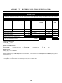
APPENDIX "B" - BATTERY CALCULATIONS (SELECTION GUIDE)
Use the form below to determine the required batteries.
IMPORTANT NOTICE
The main AC branch circuit connection for Fire Alarm Control Unit must provide a dedicated continuous power without provision of any disconnect
devices. Use #12 AWG wire with 600-volt insulation and proper over-current circuit protection that complies with the local codes.
POWER REQUIREMENTS (ALL CURRENTS ARE IN AMPERES)
Model Number Description Qty STANDBY TOTAL ALARM TOTAL
STANDBY ALARM
FA-101U Fire Alarm , 1 Det, 1 Sig X 0.066 = 0.125 =
FA-102U Fire Alarm, 2 Det, 1 Sig X 0.076 = 0.135 =
FA-1025U Fire Alarm, 5 Det, 2 Sig X 0.114 = 0.200 =
RTI-1 Remote Trouble Indicator X 0.035 = 0.035 =
2-Wire Smoke Detectors X ' 0.0001 = * 0.090 = 0.090
4-Wire Smoke Detectors X = =
Signal Load (bells, horns, strobes, and etc.) =
Total currents (Add above currents) STANDBY
(A)(B)
Total Current Requirement:
ALARM (B)______ Amps.
Battery Capacity Requirement:
([STANDBY (A) ______ ] X [(24 or 60 Hours) ___ ]) + ([ALARM (B) ______ ] X [%Alarm in Hr.] _____) =(C) ______AH
Battery Selection:
Multiply (C) by 1.20 to derate battery.
Batteries BA-104 (4.0AH) and BA-1065(6.5AH) fit into the backboxes ; all larger batteries such as BA-110(10AH) and the BA-117(17AH) require an
external battery box.
* Assuming three Initiating Circuits in alarm.
% Use 0.084 for five minutes of alarm or 0.5 for thirty minutes of alarm as a multiplier figure.
' Using the MIR-425/U 2-wire smoke detector. See Appendix "A", for other available smoke detectors .

Warranty & Warning Information
Warning Please Read Carefully
Note to End Users: This equipment is subject to terms and conditions of sale as follows:
Note to Installers
This warning contains vital information. As the only individual in contact with system users, it is your responsibility to
bring each item in this warning to the attention of the users of this system. Failure to properly inform system end-
users of the circumstances in which the system might fail may result in over-reliance upon the system. As a result, it
is imperative that you properly inform each customer for whom you install the system of the possible forms of
failure.
System Failures
This system has been carefully designed to be as effective as possible. There are circumstances, such as fire or
other types of emergencies where it may not provide protection. Alarm systems of any type may be compromised
deliberately or may fail to operate as expected for a variety of reasons. Some reasons for system failure include:
•Inadequate Installation
A Fire Alarm system must be installed in accordance with all the applicable codes and standards in order to provide
adequate protection. An inspection and approval of the initial installation, or, after any changes to the system, must
be conducted by the Local Authority Having Jurisdiction. Such inspections ensure installation has been carried out
properly.
•Power Failure
Control units, smoke detectors and many other connected devices require an adequate power supply for proper
operation. If the system or any device connected to the system operates from batteries, it is possible for the
batteries to fail. Even if the batteries have not failed, they must be fully charged, in good condition and installed
correctly. If a device operates only by AC power, any interruption, however brief, will render that device inoperative
while it does not have power. Power interruptions of any length are often accompanied by voltage fluctuations which
may damage electronic equipment such as a fire alarm system. After a power interruption has occurred,
immediately conduct a complete system test to ensure that the system operates as intended.
•Failure of Replaceable Batteries
Systems with wireless transmitters have been designed to provide several years of battery life under normal
conditions. The expected battery life is a function of the device environment, usage and type. Ambient conditions
such as high humidity, high or low temperatures, or large temperature fluctuations may reduce the expected battery
life. While each transmitting device has a low battery monitor which identifies when the batteries need to be
replaced, this monitor may fail to operate as expected. Regular testing and maintenance will keep the system in
good operating condition.
•Compromise of Radio Frequency (Wireless) Devices
Signals may not reach the receiver under all circumstances which could include metal objects placed on or near the
radio path or deliberate jamming or other inadvertent radio signal interference.
•System Users
A user may not be able to operate a panic or emergency switch possibly due to permanent or temporary physical
disability, inability to reach the device in time, or unfamiliarity with the correct operation. It is important that all
system users be trained in the correct operation of the alarm system and that they know how to respond when the
system indicates an alarm.
•Automatic Alarm Initiating Devices
Smoke detectors, heat detectors and other alarm initiating devices that are a part of this system may not properly
detect a fire condition or signal the control panel to alert occupants of a fire condition for a number of reasons, such

as: the smoke detectors or heat detector may have been improperly installed or positioned; smoke or heat may not
be able to reach the alarm initiating device, such as when the fire is in a chimney, walls or roofs, or on the other side
of closed doors; and, smoke and heat detectors may not detect smoke or heat from fires on another level of the
residence or building.
•Software
Most Mircom products contain software. With respect to those products, Mircom does not warranty that the
operation of the software will be uninterrupted or error-free or that the software will meet any other standard of
performance, or that the functions or performance of the software will meet the user’s requirements. Mircom shall
not be liable for any delays, breakdowns, interruptions, loss, destruction, alteration or other problems in the use of a
product arising our of, or caused by, the software.
Every fire is different in the amount and rate at which smoke and heat are generated. Smoke detectors cannot
sense all types of fires equally well. Smoke detectors may not provide timely warning of fires caused by
carelessness or safety hazards such as smoking in bed, violent explosions, escaping gas, improper storage of
flammable materials, overloaded electrical circuits, children playing with matches or arson.
Even if the smoke detector or heat detector operates as intended, there may be circumstances when there is
insufficient warning to allow all occupants to escape in time to avoid injury or death.
•Alarm Notification Appliances
Alarm Notification Appliances such as sirens, bells, horns, or strobes may not warn people or waken someone
sleeping if there is an intervening wall or door. If notification appliances are located on a different level of the
residence or premise, then it is less likely that the occupants will be alerted or awakened. Audible notification
appliances may be interfered with by other noise sources such as stereos, radios, televisions, air conditioners or
other appliances, or passing traffic. Audible notification appliances, however loud, may not be heard by a hearing-
impaired person.
•Telephone Lines
If telephone lines are used to transmit alarms, they may be out of service or busy for certain periods of time. Also
the telephone lines may be compromised by such things as criminal tampering, local construction, storms or
earthquakes.
•Insufficient Time
There may be circumstances when the system will operate as intended, yet the occupants will not be protected from
the emergency due to their inability to respond to the warnings in a timely manner. If the system is monitored, the
response may not occur in time enough to protect the occupants or their belongings.
•Component Failure
Although every effort has been made to make this system as reliable as possible, the system may fail to function as
intended due to the failure of a component.
•Inadequate Testing
Most problems that would prevent an alarm system from operating as intended can be discovered by regular testing
and maintenance. The complete system should be tested as required by national standards and the Local Authority
Having Jurisdiction and immediately after a fire, storm, earthquake, accident, or any kind of construction activity
inside or outside the premises. The testing should include all sensing devices, keypads, consoles, alarm indicating
devices and any other operational devices that are part of the system.
•Security and Insurance
Regardless of its capabilities, an alarm system is not a substitute for property or life insurance. An alarm system
also is not a substitute for property owners, renters, or other occupants to act prudently to prevent or minimize the
harmful effects of an emergency situation.
IMPORTANT NOTE: End-users of the system must take care to ensure that the system, batteries, telephone lines,
etc. are tested and examined on a regular basis to ensure the minimization of system failure.
Page is loading ...
Page is loading ...
Page is loading ...
Page is loading ...
-
 1
1
-
 2
2
-
 3
3
-
 4
4
-
 5
5
-
 6
6
-
 7
7
-
 8
8
-
 9
9
-
 10
10
-
 11
11
-
 12
12
-
 13
13
-
 14
14
-
 15
15
-
 16
16
-
 17
17
-
 18
18
-
 19
19
-
 20
20
-
 21
21
-
 22
22
-
 23
23
-
 24
24


Mircom LT-535 FA102U Operating instructions
- Category
- Fire protection
- Type
- Operating instructions
Mircom LT-535 FA102U is a supervised 2 zone 24VDC Fire Alarm Control Panel. It provides the following features:
- 2 class B detection zones
- 1 class B signal zone, 1.25A
- Alarm and trouble relay contacts
- Remote trouble and A.C. ON indication
- Individual zone silence/disconnect switches
- Trouble silence switch
- Subsequent alarm operation
- LED indicators for zone Alarm and Trouble, A.C. On, Battery Fault, Ground Fault, Common Trouble, Signal Trouble and Signal Silenced The device can be used in various applications, such as:
- Homes
- Offices
- Schools
- Hospitals
- Commercial buildings
- Industrial facilities
Ask a question and I''ll find the answer in the document
Finding information in a document is now easier with AI
Related papers
-
Mircom LT-513 FA-101T Operating instructions
-
-
-
-
-
Mircom LT-657 FX-2000 Operating instructions
-
-
-
-
Other documents
-
Premier Mounts PSD-CAM User manual
-
 Touchboards PSD-VHS Installation guide
-
EDWARDS 700 Series Installation guide
-
CERBERUS PYROTRONICS RL-30/RL-40 System 3 Remote Alarm Lamp User guide
-
 Audio Authority MR-2900 Installation guide
-
-
 Edwards Signaling E-HD Fixed-Temperature-Rate-of-Rise Heat Detector Installation guide
-
ATEN CS102U User manual
-
 SILENT KNIGHT 5895XL 6A Intelligent Remote Power Supply User manual
-
usi USI-2177 Owner's manual


