Page is loading ...

THIS INSTRUCTION BOOKLET CONTAINS IMPORTANT SAFETY INFORMATION.
PLEASE READ AND KEEP FOR FUTURE REFERENCE.
Whalen Furniture Manufacturing Page 1 Factory: 10944
Date 2014-10-10 Rev. 1 Factory: FOCIDI
Santa Fe 3-in-1
TM
Console
Stock #
XLSFEC54-WN
U.S. Patent 8,622,005
This item is designed to be a 3-in-1 configuration. Please choose the option that best suits your
needs. DO NOT discard any of the hardware or parts that you will not use on your chosen option.
This will allow you to use this TV Console in different configurations at a later date, if desired.
ADULT ASSEMBLY REQUIRED
If you have any questions regarding assembly or if parts are missing, DO NOT return this item to the
store where it was purchased. Please call our customer service number and have your instructions
and parts list ready to provide the model name, part name or factory number:
1-866-942-5362
Pacific Standard Time: 8:30 a.m. - 4:30 p.m., Monday - Friday
Or visit our web site 24 hours a day, 7 days a week for product assistance at
www.whalenstyle.com
Or e-mail your request to parts@whalenfurniture.com
LOT NUMBER:
DATE PURCHASED: / /
TV

Stock # XLSFEC54-WN
Please call for replacement parts or assistance:
1-866-942-5362
Whalen Furniture Manufacturing Page 2 Factory No. 10944
MANUFACTURER: Whalen Furniture Manufacturing
CATALOG: Santa Fe 3-in-1
TM
Console (XLSFEC54-WN)
DATE OF MANUFACTURE: October 2014
MADE IN CHINA
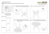
1. Please read the Assembly Instructions prior to assembling this product.
2. Remove all hardware from the box and sort by size.
3. Check to see that all hardware and parts are present BEFORE assembling.
4. Ask a friend to assist you with the assembly of this furniture.
5. To avoid damage, assemble the product on a sturdy, level and protective surface.
6. Please wait until all steps are completed before fully tightening bolts.
7. Make sure all bolts are tightly fastened before the unit is used.
MAXIMUM RECOMMENDED WEIGHT LOADS
MAXIMUM LOAD 50 lb. (22.6 kg)
GENERAL INFORMATION
,
TIPS and TRICKS
This product is sold with one set of Tipping Restraint Hardware Kit. You must install the
Tipping Restraint Hardware between the wall and the TV console to prevent any accidents or
damages. When properly installed, this restraint can provide protection against the
unexpected tipping of the unit due to small tremors, bumps or climbing. The restraint is only a
deterrent and is not a substitute for proper adult supervision. Use of tip-over restraints may
only reduce, but not eliminate, the risk of tip-over.
FITS UP TO MOST 65” FLAT PANEL TVs
MAXIMUM LOAD 135 lb. (61.2 kg)
FITS UP TO MOST 65” FLAT PANEL TVs
WITHOUT SWIVELING BRACKET
MAXIMUM LOAD 135 lb. (61.2 kg)
PLACE TV BEHIND THE STOPPER
THIS UNIT IS NOT INTENDED FOR USE WITH CRT TVS. USE ONLY
WITH FLAT PANEL TVS AND AUDIO/VIDEO EQUIPMENT MEETING RECOMMENDED SIZE
AND WEIGHT LIMITS. NEVER USE WITH LARGER/HEAVIER THAN RECOMMENDED FLAT
PANEL TVS OR EQUIPMENT. TO AVOID INSTABILITY, PLACE FLAT PANEL TV IN THE
CENTRE OF THE UNIT; THE BASE OF THE TELEVISION MUST BE ABLE TO REST ON THE
SUPPORTING SURFACE OF THE UNIT WITHOUT OVER-HANGING THE EDGES.
IMPROPERLY POSITIONED FLAT PANEL TVS, OR FLAT PANEL TVS OR OTHER
EQUIPMENT THAT EXCEED RECOMMENDED SIZE AND WEIGHT LIMITS COULD FALL OFF
OR BREAK THE UNIT, CAUSING POSSIBLE SERIOUS INJURY.

Stock # XLSFEC54-WN
Please call for replacement parts or assistance:
1-866-942-5362
Whalen Furniture Manufacturing Page 3 Factory No. 10944
Parts and Hardware List
Please read completely through the instructions and verify that all listed parts and hardware
are present before beginning assembly.
A- Top Shelf with Metal Frame (1) B- Middle Shelf with Metal Frame (1)
C- Bottom Shelf with Metal Frame (1)
D- Spine (1) E- Left Side Frame (1)
F- Right Side Frame (1) G- Swiveling Bracket (1) H- Mounting Frame (1)
I- Monitor Bracket (2) J- Metal Bracket (2) K- Cable Wheel (3)
(1) 1/2” Bolt (4+1 extra) (2) 5/8” Bolt (20+1 extra) (3) 1-1/4” Bolt (12+1 extra)
(4) 2-1/4” Bolt (6+1 extra) (5) Lock Washer (36+1 extra) (6) Flat Washer (36+1 extra)
IR
IL

Stock # XLSFEC54-WN
Please call for replacement parts or assistance:
1-866-942-5362
Whalen Furniture Manufacturing Page 4 Factory No. 10944
Parts and Hardware List
Please read completely through the instructions and verify that all listed parts and hardware
are present before beginning assembly.
(7) 2-1/2” Lag Bolt (4) (8) Large Flat Washer (4+1 extra) (9) Concrete Anchor (4)
(10) Large Floor Leveler (1) (11) Acrylic Stopper (1) M4 Allen Wrench (2)
3/16” Allen Wrench (1) Touch-up Pen (1) Tipping Restraint Hardware Kit (1)
(Inside Plastic Bag)
TV Mounting Kit
M4 x 12 Bolt (4) M4 x 30 Bolt (4) M5 x 12 Bolt (4) M5 x 30 Bolt (4)
M6 x 12 Bolt (4) M6 x 35 Bolt (4) M8 x 16 Bolt (4) M8 x 40 Bolt (4)
M4 Lock Washer
(4) M5 Lock Washer (4) M6 Lock Washer (4) M8 Lock Washer (4)
Large Spacer (4) Small Spacer (4) M4/M5 Flat Washer (8) M6/M8 Flat Washer (4)
Tools required: Allen wrench (provided) and Phillips screwdriver (not provided).

Stock # XLSFEC54-WN
Please call for replacement parts or assistance:
1-866-942-5362
Whalen Furniture Manufacturing Page 5 Factory No. 10944
Assembly Instructions
NOTE: Please do not fully tighten all bolts until you finish assembling all parts. Once
assembled, go back and fully tighten all bolts. This will make the assembly easier.
1. Unpack the unit and confirm that you have all the hardware and required parts.
2. Align and attach 3 Shelves (A, B and C) between the Left and Right Side Frames (E and F) by
inserting the 1-1/4” Bolts (3) with Lock Washers (5) and Flat Washers (6) through the drilled
holes on the metal frame side rails and screw into the threaded sockets on the side frames. As
shown. Make sure that the back edges are even with each other and the metal frames will
face the floor when the unit is turned upright.
3. Tightly screw the Large Floor Leveler (10) into the threaded insert underneath the Bottom
Shelf (C) and set it to the correct height, as shown above.
6
5
3
E/F
A/B/C
B
A
C
E
F
C
10
Flat Washer
(12 used in this step)
⑥
Lock Washer
(12 used in this step)
⑤
1-1/4” Bolt
(12 used in this step)
③
Large Floor Leveler
(1 used in this step)
⑩

Stock # XLSFEC54-WN
Please call for replacement parts or assistance:
1-866-942-5362
Whalen Furniture Manufacturing Page 6 Factory No. 10944
Assembly Instructions
4. Stand the unit upright.
5. Fasten 2 Metal Brackets (J) to connect the Top Shelf Metal Frame (A) with both Side Frames
(E and F), using four 5/8” Bolt (2) and four Washers (5 and 6) per bracket. As shown.
NOTE
: If mounting the TV to the Floating Swivel Mount, skip ahead to PAGE 9.
A
B
C
E
F
A
E/F
J
6
5
2
Flat Washer
(8 used in this step)
⑥
Lock Washer
(8 used in this step)
⑤
5/8” Bolt
(8 used in this step)
②

Stock # XLSFEC54-WN
Please call for replacement parts or assistance:
1-866-942-5362
Whalen Furniture Manufacturing Page 7 Factory No. 10944
Assembly Instructions for Table-top Console
NOTE
: You must install the Acrylic TV Stopper to prevent TV from tipping when placing your flat
panel television directly on the table-top console. If you plan to mount the TV to the wall,
proceed directly to next page.
6. Remove the tape of Acrylic Stopper (11) and place it in the cut-out of the acrylic stopper
template on the Top Shelf (A). Make sure that it is properly aligned before applying pressure.
7. Remove the acrylic stopper template from the Top Shelf (A) carefully.
NOTE: When you place the TV on the stand, make sure that the base of the TV is behind the
Acrylic Stopper (11). This will help prevent the TV from sliding off your stand if your stand is
accidently bumped or tipped.
Acrylic Stopper
(1 used in this step)
⑪
A
A
A

Stock # XLSFEC54-WN
Please call for replacement parts or assistance:
1-866-942-5362
Whalen Furniture Manufacturing Page 8 Factory No. 10944
Assembly Instructions for Table-top Console
Tools required: Allen wrench (provided), Phillips screwdriver, Mallet, Power Drill, and 3/8” Drill Bit.
8. Position the assembled console at the desired location against a wall. If necessary, adjust the
installed Large Floor Leveler (10) and the pre-attached Small Floor Levelers at the bottom of
Side Frames (E and F) to level the unit. Now, follow the instructions printed on the plastic bag
containing the Tipping Restraint Hardware to attach the tip-over restraint to the Top Shelf (A)
and the wall.
NOTE: YOU MUST USE THIS TIPPING RESTRAINT TO ATTACH THIS UNIT TO
THE WALL, TO PREVENT ACCIDENTS AND/OR INJURIES.
9. The table-top console is now ready for use. Be sure to position your Flat Panel TV in the
center of the console.
NOTE: For Tilting Wall Mount, proceed to PAGE #18.
TV
E
F
C
E/F

Stock # XLSFEC54-WN
Please call for replacement parts or assistance:
1-866-942-5362
Whalen Furniture Manufacturing Page 9 Factory No. 10944
10. Align and attach the Spine (D) to the back of the console with six 2-1/4” Bolts (4) and six
Washers (5 and 6). Tighten the bolts with the enclosed M4 Allen Wrench. Make sure the
threaded sockets for the Cable Wheel (K) face backward.
4
5
6
A
B
C
D
4
5
6
4
5
6
2-1/4” Bolt
(6 used in this step)
④
Flat Washer
(6 used in this step)
⑥
Lock Washer
(6 used in this step)
⑤
Assembly Instructions for
Floating Swivel Mount

Stock # XLSFEC54-WN
Please call for replacement parts or assistance:
1-866-942-5362
Whalen Furniture Manufacturing Page 10 Factory No. 10944
Assembly Instructions for Floating Swivel Mount
11. Fasten the Swiveling Bracket (G) to the top of the Spine (D) with six 5/8” Bolts (2) and six
Washers (5 and 6) by the enclosed M4 Allen Wrench. Make sure the pivoting bolt head is up.
NOTE: The Spine can provide two height options for your TV set. Refer to your TV size and
adjust the Swiveling Bracket at the desired height for optimum viewing.
Flat Washer
(6 used in this step)
⑥
Lock Washer
(6 used in this step)
⑤
2
6
5
2
6
5
UP
D
G
2
6
5
2
6
5
G
D
5/8” Bolt
(6 used in this step)
②

Stock # XLSFEC54-WN
Please call for replacement parts or assistance:
1-866-942-5362
Whalen Furniture Manufacturing Page 11 Factory No. 10944
Assembly Instructions for Floating Swivel Mount
12. Hold and attach the flat side of the Mounting Frame (H) to the Swiveling Bracket (G) using four
1/2” Bolts (1) and four Washers (5 and 6). Make sure that the recess holes on the Mounting
Frame are at the bottom.
H
G
D
BACK
H
D
G
1
5
6
5
6
1
5
6
1
1/2” Bolt
(4 used in this step)
①
Flat Washer
(4 used in this step)
⑥
Lock Washer
(4 used in this step)
⑤

Stock # XLSFEC54-WN
Please call for replacement parts or assistance:
1-866-942-5362
Whalen Furniture Manufacturing Page 12 Factory No. 10944
Mounting the Monitor Brackets to a television with a Flat Back
NOTE
: For televisions with a curved or recessed back, proceed directly to next page.
13. Determine the correct diameter of the Bolt the TV requires by hand threading them into the
threaded insert on the back of the TV. If you encounter any resistance, stop immediately. If
you are unable to find the correct Bolt, consult a local hardware store.
14. Follow the appropriate diagram above to attach the Monitor Brackets (IL/IR) to the back of the
TV with the selected fasteners. Make sure the Monitor Brackets are vertically centered and
level with each other. Secure the bolts with a Phillips screwdriver. DO NOT over tighten the
bolts.
NOTE: Lean the TV up against a wall, or other solid surface, when attaching the Monitor
Brackets. DO NOT place the TV face down on the glass as this may cause permanent damage.

Stock # XLSFEC54-WN
Please call for replacement parts or assistance:
1-866-942-5362
Whalen Furniture Manufacturing Page 13 Factory No. 10944
Mounting the Monitor Brackets to a television with a Curved/Recess Back
15. Determine the correct diameter of the Bolt the TV requires by hand threading them into the
threaded insert on the back of the TV. If you encounter any resistance, stop immediately. If
you are unable to find the correct Bolt consult a local hardware store.
16. Follow the appropriate diagram above to attach the Monitor Brackets (IL/IR) to the back of the
TV with the selected fasteners. Make sure the Monitor Brackets are vertically centered and
level with each other. Secure the bolts with a Phillips screwdriver. DO NOT over tighten the
bolts.
NOTE: Lean the TV up against a wall, or other solid surface, when attaching the Monitor
Brackets. DO NOT place the TV face down on the glass as this may cause permanent damage.

Stock # XLSFEC54-WN
Please call for replacement parts or assistance:
1-866-942-5362
Whalen Furniture Manufacturing Page 14 Factory No. 10944
Assembly Instructions for Floating Swivel Mount
MAKE SURE ALL BOLTS ARE TIGHT AND THE SPINE IS AT A 90 DEGREE ANGLE.
USE A QUALITY LEVEL TO VERIFY THE MOUNTING FRAME IS LEVEL PRIOR TO
INSTALLATION OF TV.
17. Once the Monitor Brackets (IL/IR) are attached onto the back of television, ask for assistance
to lift the television up to hang the Monitor Brackets (IL/IR) onto the Mounting Frame (H). Set
the hooks on the Monitor Brackets over the Mounting Frame and then lower them onto the
bars of the Mounting Frame.
NOTE: Loosen the Lock Bolts that is pre-attached to the Monitor Brackets to ensure an easy
fit at the bottom hooks.
18. Center the television and tighten both Lock Bolts with a long Phillips screwdriver until they hit
the underside of the Mounting Frame (H) to secure it in place.
H
1
2
H
IL/IR
H
IL/IR
IR
IL
D

Stock # XLSFEC54-WN
Please call for replacement parts or assistance:
1-866-942-5362
Whalen Furniture Manufacturing Page 15 Factory No. 10944
Assembly Instructions for Floating Swivel Mount
19. The Monitor Brackets (IL/IR) can tilt up to 11˚ downward and 5˚ upward, depending on your
optimum viewing position. Keep the enclosed 3/16”Allen Wrench to ensure the Tilt Adjustment
Knobs remain tightly fastened.

Stock # XLSFEC54-WN
Please call for replacement parts or assistance:
1-866-942-5362
Whalen Furniture Manufacturing Page 16 Factory No. 10944
Assembly Instructions for Floating Swivel Mount
20. Attach 3 Cable Wheels (K) onto the backside of the Spine (D) with the 5/8” Bolts (2).
NOTE
: You can use the Cable Wheels to help keep the entertainment center’s cables and
cords organized.
K
2
D
D
5/8” Bolt
(6 used in this step)
②

Stock # XLSFEC54-WN
Please call for replacement parts or assistance:
1-866-942-5362
Whalen Furniture Manufacturing Page 17 Factory No. 10944
Assembly Instructions for Floating Swivel Mount
Tools required
: Allen wrench (provided), Phillips screwdriver, Mallet, Power Drill, and 3/8” Drill Bit.
21. Position the assembled console at the desired location against a wall. If necessary, adjust the
installed Large Floor Leveler (10) and the pre-attached Small Floor Levelers at the bottom of
both Side Frames (E and F) to level the unit. Now, follow the instructions printed on the plastic
bag containing the Tipping Restraint Hardware to attach the tip-over restraint to the Spine and
the wall.
NOTE: YOU MUST USE THIS TIPPING RESTRAINT TO ATTACH THIS UNIT TO THE WALL,
TO PREVENT ACCIDENTS AND/OR INJURIES.
22. The console is now ready for use. Swivel the TV left-or-right for optimum viewing control.
E/F
E
F
C

Stock # XLSFEC54-WN
Please call for replacement parts or assistance:
1-866-942-5362
Whalen Furniture Manufacturing Page 18 Factory No. 10944
2.50" (63 mm)
0.20" (5 mm)
Assembly Instructions for Universal Wall Mount
Installing the Mounting Frame onto a WOODEN STUD WALL
NOTE: If you are mounting your TV onto brick, solid concrete or concrete block walls, skip this
section. This assembly requires an electric drill, level and stud finder (not included).
23. Using a stud finder, locate the edges of the wood studs. Find the center line of each stud and
draw a vertical reference line on the wall over each one. Place the Mounting Frame (H) level
against the wall where you intend to mount the TV. Using the Mounting Frame (H) as a
template, mark 4 drill points (2 on top, 2 on bottom) with a pencil on the vertical reference lines
you just drew.
24. With an electric drill (not included), drill 3/16 inch diameter holes to at least 2½ inch deep on
the 4 drill points. While holding the Bracket Plate in place, loosely screw in the Lag Bolts (7).
25. Secure the Mounting Frame (H) to wall with Lag Bolts (7) and the Washers (8) at the drill
points. Tighten the bolts firmly, but be careful not to over-tighten.
The following steps are only for those who wish to mount their
TV directly to the wall. If you have already mounted your TV to
the Swinging Floater or plan to display your TV on the top
surface of the Console, disregard the following steps.
Do not over-tighten the Lag Bolts. Tighten the Lag Bolts only until the
Lag Bolt Washer is pulled firmly against the metal plate of the Mounting Frame. If there is a
layer of drywall or other material, this drywall or other material may not exceed 5/8 inch in
thickness. Failure to heed this caution may result property damage and/or personal injury.

Stock # XLSFEC54-WN
Please call for replacement parts or assistance:
1-866-942-5362
Whalen Furniture Manufacturing Page 19 Factory No. 10944
Assembly Instruction for installing the Mounting Frame onto BRICK,
SOLID CONCRETE OR CONCRETE BLOCK WALLS
NOTE:
If you are mounting your TV to a wall with wooden studs, skip this section. This
assembly requires an electric drill and level (not included).
26. Begin by placing the Mounting Frame (H) level against the wall where you intend to mount the
TV. Using the Mounting Frame (H) as a template, mark 4 drill points with a pencil.
27. With an electric drill (not included) on its low setting, drill 7/16 inch diameter holes to at least
2½ inch deep. Insert the Concrete Anchors (9) into the pre-drilled holes so that they are flush
with the wall.
28. Place the Mounting Frame (H) level in the desired position against the wall. Secure the
Mounting Frame (H) to the wall with the Lag Bolts (7) and the Washers (8) at the drill points.
Tighten the Bolts firmly, but be careful not to over-tighten.
2.50" (63 mm)
0.4375" (11 mm)
Concrete Anchors should only be used for masonry mounting.
NEVER use the wall anchors to mount the unit to drywall.
Maximum weight 135 lb. (61.2 kg)

Stock # XLSFEC54-WN
Please call for replacement parts or assistance:
1-866-942-5362
Whalen Furniture Manufacturing Page 20 Factory No. 10944
Assembly Instructions
29. Attach the Monitor Brackets (IL/IR) to the back of the television following steps 13 & 14, or 15
& 16, depending on the type of TV that you own.
30. Ask for assistance to lift the television up to attach the Monitor Brackets (IL/IR) onto the
Mounting Frame (H). Set the hooks on Monitor Brackets over the Mounting Frame and then
lower them onto the bars of the Mounting Frame. Loosen the Lock Bolts that are pre-attached
on the Monitor Brackets to ensure an easy fit at the bottom hooks. Proceed to center the television.
31. When the TV is in its intended position, tighten both Lock Bolts with a long Phillips screwdriver
until they hit the underside of the Mounting Frame (H) to ensure your TV is safe and secure.
32. Place the assembled console under your TV. Finally, connect the A/V and power cables to your
TV. You are now ready to enjoy your wall-mounted Flat Panel TV.
1
2
/