Page is loading ...

Close Coupled Motor Driven
Centrifugal Pump
Type "B" End Suction Centrifugal
1134 0694
OWNER’S MANUAL
Closed Coupled Motor Driven
Centrifugal Pump
© 2014 Pentair Ltd. All Rights Reserved. F00634 (03/19/14)
293 WRIGHT STREET, DELAVAN, WI 53115 WWW.BERKELEYPUMPS.COM
PH: 888-782-7483

F00634
................................................................................................................................................................. 3
General Information .................................................................................................................................... 4-5
Foundation ...................................................................................................................................................... 5
Centrifugal Pump Suction Connection .........................................................................................................6-9
Swimming Pool Pump Suction Connection .............................................................................................10-11
Discharge Connection .............................................................................................................................12-13
Electrical Connection .................................................................................................................................... 14
General Information ...................................................................................................................................... 15
Determine Pump Rotation ............................................................................................................................ 16
Pump Priming ............................................................................................................................................... 17
General Information ...................................................................................................................................... 18
Packing Ring Replacement .......................................................................................................................... 19
Mechanical Shaft Seal ............................................................................................................................. 20-23
General Information ...................................................................................................................................... 24
Parts Breakdown .....................................................................................................................................25-26
Chart ............................................................................................................................................................. 27
Warranty ....................................................................................................................................................... 28
Page
Table of Contents 2

F00634
When you see
this symbol on your pump or in this manual, look for
one of the following signal words and be alert to the
potential for personal injury:
warns about hazards that cause
serious personal injury, death or major property
damage if ignored.
warns about hazards that or
cause serious personal injury, death or major property
damage if ignored.
warns about hazards that or
cause minor personal injury or property damage if
ignored.
The label indicates special instructions which
are important but not related to hazards.
Keep safety labels in good condition.
Replace missing or damaged safety labels.
Electrical Safety
General Safety
Do not allow pump, piping, or any other system
component containing water to freeze. Freezing may
damage system, leading to injury or flooding. Allowing
pump or system components to freeze will void
warranty.
Pump approved liquids only with this pump.
Periodically inspect pump and system components.
Wear safety glasses at all times when working on
pumps.
Keep work area clean, uncluttered and properly
lighted; store properly all unused tools and equipment.
Keep visitors at a safe distance from the work areas.
Make workshops childproof; use padlocks and master
switches; remove starter keys.
Swimming Pool and Spa Installation Safety
Read and follow instructions in owner’s
manual when installing and operating equipment. Have
a trained pool professional perform all pressure tests.
1. Do not connect system to a high pressure or city
water system.
2. Install pump with at least 2 hydraulically balanced
main drains equipped with correctly installed,
screw-fastened, anti-entrapment certified covers.
See Page 11.
3. Trapped air in system can cause explosion.
BE SURE all air is out of system before operating or
testing equipment.
• Checkallclamps,bolts,lids,andsystem
accessories before testing.
• Releaseallairinsystembeforetesting.
• TightenBerkeleytraplidsto30ft.lbs.(4.1kg-cm)
torque for testing.
• Waterpressurefortestmustbelessthan25PSI
(172kPa).
• WaterTemperaturefortestmustbelessthan
100
°
F.(38
°
C).
• Limittestto24hours.Aftertest,visuallycheck
system to be sure it is ready for operation. Remove
trap lid and retighten hand tight only.
These parameters apply to Berkeley
equipment only. For non-Berkeley equipment,
consult manufacturer.
Ground pump before
connecting to power
supply.
Safety 3

F00634
NEVER walk or reach under a suspended pump.
DO NOT screw an eye bolt into the motor housing and
attempt to lift assembly! The lifting point built into the
motor case is not designed to support the combined
weight of the motor and pump.
The crane or hoist must have a capacity in excess of
the combined weight of the motor and pump. Use a
minimum of two chains or straps to lift motor/pump
assembly. Each chain or strap must have a capacity in
excess of the combined weight of the motor and pump.
Wrap the first chain or strap under the fan end of the
motor up tight against the motor feet, and the second
chain or strap under the pump bracket between the
pump end and the motor.
Raise motor/pump assembly slowly to ensure that the
chains or straps will not slip when put under tension.
Balance motor and pump with chains or straps to
maintain proper weight distribution. If not balanced,
release tension on the chains or straps and readjust.
2498 0497
Installation 4

F00634
Locatethepumpasnearthewatersourceaspractical.Make
the pipe run as short and straight as possible, especially if a
suction lift is required.
Careful attention should be taken to assure that net positive
suctionheadavailable (NPSHA)exceedsnetpositive suction
headrequired(NPSHR)bythepumporreducedperformance
and severe pump damage may result. If in doubt, check
with your nearest Berkeley professional dealer. Install pump
in a clean, dry and drained location readily accessible for
inspection and maintenance. Provide ample ventilation.
Refer to illustrations at right.
Use care and proper
equipment when handling pump for installation. Pump should
be set on a concrete foundation which is sufficiently substantial
to absorb vibration and which provides a permanent and rigid
support.
System piping should be at least one commercial pipe size
larger than pump connections and flow velocity should not
exceed eight (8) feet per second. In pool installation, flow
velocityshouldnotexceedsix(6)feetpersecond.
Take care to align piping with pump case.
Misalignment or excessive pipe strain can cause distortion of
pump components resulting in rubbing, breakage and reduced
pump life.
Support pipe in such a way that no force is exerted on pump
connections. Check alignment as follows: with the pump shut
down and isolation valves closed, remove pipe flange bolts.
If the mating flanges come apart or shift, misalignment is
present and causing pressure on the connections. Adjust pipe
supports until flanges mate without any force. This procedure
can be done throughout piping system.
Refer to Pages 10 and 11 for installation instructions for
swimming pool circulating pump applications. Refer to Pages
6 through 9 for recommended and not recommended practices
in suction connections in centrifugal installations.
Refer to illustrations on Page 12 and 13 for recommended and
not recommended practices in discharge connections.
Disconnect power to pump before servicing.
Check voltage and phase stamped on pump motor nameplate
before wiring. Be sure they agree with your electric current
supply. They be the same. If in doubt, check with your
local power company.
Refer to illustration on Page 14 for minimum recommended
pumping panel components that help safeguard your pump
during operation.
• There are several types of permanent pump/ foundation
installations in use. Those pictured above are typical.
• If grout is used, top ofconcrete should be left rough to
provide a good bonding surface.
• Foundationshouldslopeawayfrompumptopreventliquid
from pooling.
Installation 5

F00634
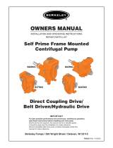
503 0194
Short length of straight pipe after reducer.
( 2 times pipe diameter minimum )
Suction
Gauge
Straight run, short as possible but
at least 6 times pipe diameter ("D")
after elbow to stabilize flow.
As close
as possible
Pipe diameter ("D")
4 x "D"
minimum
1 x "D" minimum
from bottom
Strainer / Foot Valve
To keep debris from entering
pump suction and to maintain
pump prime after shut-off.
Eccentric Reducer
flat side up.
See foundation
section.
Support pipe
as required
NOTICE: All connections
must be air tight.
For Han-Dee Primer
connection, see start-up.
Standard or long
radius elbow.
Slope upward
to pump.
Strainer prevents debris from entering pump
suction and prevents entrapment hazard.
Foot valve maintains pump prime after
shutoff.
See Pages 10 and 11 for
Swimming Pool Installation requirements.
• Usepipe,tubing,orreinforcedhosetomakesuction
connection. Hose must have sufficient strength to
resist collapse under the pressure differential that
occurs while pump is running.
• Suctionpipesizeshouldbeatleastonecommercial
pipe size larger than opening of pump inlet. Flow
velocity should not exceed 8 ft./sec.
• Suctionscreenmustscreenoutsolidsthatcouldclog
pump impeller.
• Suctionscreen area must be at least four times
suction pipe area.
• Net Positive Suction Head Available (NPSHA)
must exceed Net Positive Suction Head Required
(NPSHR)bythe pump orreduced performance and
severe pump damage may result.
• All suction piping must have continuous rise to the
pump suction inlet. A 1/4 inch per foot minimum
slope is recommended.
Installation • Centrifugal Pump Suction Connection 6
Suction Lift

F00634
1152 0794
Do not use
Concentric
Reducer.
Concentric Reducer causes high spots
along the suction line resulting in
air pockets.
Do not install valves
in suction line.
Long run
not recommended
Unsupported
pipe causes
excessive stress
on pump and fittings.
Excess use of pipe fittings
means potential
air leaks.
No support or
uneven mounting
not recommended.
Pipe diameter
("D") undersized
reduces performance
High suction
lift should
be avoided.
Less than
4 x "D"
Vortex caused by
insufficient submergence
may cause pump to
lose prime.
No strainer
may cause
pump to
clog.
Insufficient bottom
clearance
Elbow immediately in
front of pump intake
not recommended.
• Suctionpipeslopingdownwardtopumpinletwilltrap
air which will reduce performance and may cause
pump to lose prime.
• Suction piping that is undersized will create excess
friction losses that may cause cavitation and a
reduction in pump performance.
• Excess fittings and bends in suction line results in
trapped air, reduced performance, and high friction
losses which may cause cavitation.
See Pages 10 and 11 for
Swimming Pool Installation requirements.
Installation • Centrifugal Pump Suction Connection 7
Suction Lift

F00634
702 0294
Water under
pressure
Support pipe
as required
Short run of straight pipe after reducer
(2 times pipe diameter).
Eccentric Reducer
flat side up.
Maintain minimum liquid
level to prevent vortexing.
Isolation Valve
full open when
pumping.
Standard or
long radius
elbow.
Suction
Gauge
Straight run, short as possible but
at least 6 times pipe diameter after
pipe fitting to stabilize flow.
Slope upward to pump.
• Usepipe,tubing,orreinforcedhosetomakesuction
connection. Hose must have sufficient strength to
resist collapse under the atmospheric pressure
differential that may occur while pump is running.
• Itisimportant,evenwithafloodedsuctioncondition,
that proper pipe fittings are used so water is delivered
to impeller eye with a smooth flow and consistent
velocity.
• Suctionpipesizeshould beatleast onecommercial
pipe size larger than opening of pipe inlet. Flow
velocity should not exceed 8 ft./sec.
• An isolation valve is used in a pressurized suction
pipe to permit servicing pump.
• Pipingrunandconnectionfittingsshouldbeproperly
aligned and independently supported to reduce strain
on pump case.
• If solids are present, a strainer should be used to
protect the pump.
See Pages 10 and 11 for
Swimming Pool Installation requirements.
Installation • Centrifugal Pump Suction Connection 8
When fLooded Suction exiStS

F00634
703 0294
Water under
pressure
Inverted Eccentric Reducer
may result in air pocket.
Do not leave
valve partially
closed.
Check Valve
in suction pipe
not needed.
Unsupported
pipe causes
excessive stress
on pump and fittings.
Concentric Reducer may
cause
air pockets.
Elbow immediately in front
of pump intake not recommended.
Valve in upward
position may trap
air.
Miter elbow or short
radius elbow not
recommended.
• Suction piping that is undersized will create excess
friction losses that may cause cavitation and a
reduction in pump performance.
• Excess fittings and bends in suction line results in
trapped air, reduced performance, and high friction
losses which may cause cavitation.
• If check valve is required for back flow prevention,
locate on the discharge side of pump.
See Pages 10 and 11 for
Swimming Pool Installation requirements.
When fLooded Suction exiStS
Installation • Centrifugal Pump Suction Connection 9

F00634
• At least two hydraulically balanced main drains for
each pump suction line. Main drain must be at least
three feet center to center.
• The pump suction system must provide protection
against the hazard of suction entrapment or hair
entrapment/entanglement. All suction outlet covers
must be maintained. They must be replaced if
cracked, broken, or missing.
• If 100% of the pump’s flow comes from the main
drain system, the maximum water velocity in the
pump suction hydraulic system must be six feet
per second or less evenifonemaindrain(suction
fitting)iscompletelyblocked.
• The system must not be able to operate with the
pump drawing water from only one maindrain(that
is, there must be at least two main drains connected
tothepumpwheneveritisrunning.)However,iftwo
main drains run into a single suction line, the single
suction line may be equipped with a valve which will
shut off both main drains from the pump.
Installation • Swimming Pool Pump Suction Connection 10
typicaL SWimming pooL

F00634
Follow the guidelines below for a pump installation
which minimizes risk to users of pools, spas, and hot
tubs.
The pump suction system must provide protection
against the hazard of suction entrapment or hair
entrapment/entanglement.
All suction outlet covers must be maintained. They
must be replaced if cracked, broken, or missing.
All suction outlets must have correctly installed, screw-
fastened covers in place.
Suction outlet covers must have been tested by a
nationally recognized testing laboratory and found to
comply with the latest ASME/ANSI Specification for
Suction Fittings For Use in Swimming Pools, Spas, Hot
Tubs, and Whirlpool Bathtub Applications.
An NSF certified hair and lint strainer must be installed
with the pump in order to comply with NSF Standard
50.
Provide at least two hydraulically balanced main
drains,withcovers (seePage10),foreachswimming
pool pump suction line. The centers of the main drains
(suctionfittings)mustbeatleastthreefeetapart.
The system must be built so that it cannot operate with
thepumpdrawingwaterfromonlyonemaindrain(that
is, there must be at least two main drains connected to
thepumpwheneveritisrunning).However,iftwomain
drains run into a single suction line, the single suction
line may be equipped with a valve which will shutoff
both main drains from the pump.
More than one pump can be connected to a single
suction line as long as the requirements above are
met.
The maximum water velocity through any suction outlet
must be 1.5 feet per second. In any case, do not
exceed the suction fitting’s maximum designed flow
rate.
If 100% of the pump’s flow comes from the main
drain system, the maximum water velocity in the
pump suction hydraulic system must be six feet per
secondorlessevenifonemaindrain(suctionfitting)is
completely blocked.
Installation • Swimming Pool Pump Suction Connection 11
Suction RequiRement

F00634
Expansion joint with tie
rods where needed.
Use Concentric Reducer
to mimimize friction losses.
This fitting may be used to
check shut-off head.
Isolation
Valve
Support piping
as required
This view shows discharge
fittings typical of pump
with flooded suction.
These two views show discharge
fittings typical of pump with
suction lift.
Discharge pipe diameter at
least one nominal pipe size
larger than discharge opening
in pump.
Non-Slam or
spring loaded
check valve.
Isolation valve to
permit servicing of
check valve or pump.
Discharge
Priming
Valve
Align piping to
minimize flange
stress.
706 0294
Pressure
Gauge
• Use pipe, tubing or reinforced hose to make
discharge connection. Material selected must have
sufficient strength for operating pressures.
• Discharge pipeshouldbesizedso thatflow velocity
is below 8 feet per second.
• Use non-slamming check valves to prevent
hydraulicshock(waterhammer).
• Use gate, ball, or butterfly valve for isolation. Valve
should be full open during operation.
• Maintain proper pipe size throughout discharge
system, using as few elbows and tees as possible to
keep friction loss to a minimum.
• Install pressure gauge after reducer as shown to
check operating pressure or shut-off head.
Installation • Discharge Connection 12

F00634
Do not use Gate Valve
to throttle flow.
Avoid abrupt change
in pipe size.
708 0294
Avoid undersized
pipe diameter.
Do not f
orce alignment
that can cause flange
stresses
.
Do not leave
pipe unsupported.
Avoid check valves
that cause hydraulic
shock.
• Avoid excess friction loss caused by numerous
fittings, insufficient pipe diameter, and sharp turns in
pipe run.
• Swing type check valves can permit build-up of
reverse velocity before closing causing hydraulic
shock or “water hammer.”
Installation • Discharge Connection 13

F00634
884 0494
1
2
3
AMP TIME
4
5
Incoming Power
L1 L2 L3
AUTO
STOP
HAND
START
Minimum recommended components to protect your
pump during operation. Check all local electrical codes
prior to installation.
NEMA 3R Enclosure
Installation • Electrical Connection 14

F00634
Before pump is put into operation, rotational direction
must be checked to assure proper performance of
pump. Refer to illustration on Page 16.
Disconnect power to pump before
servicing.
Do not attempt any wiring changes without first
disconnecting power to pump.
Pump priming is the displacement of air with water
in the pump and suction piping. Pump
completely filled with water when operating.
Refer to Page 17 for instruction on the following
conditions:
1.Suction lift with priming pump (water source
belowpump).
2.Suction lift with foot valve (water source below
pump).
3.Flooded suction (water source above pump,
or incoming water pressure is greater than
atmosphericpressure).
SPECIALCASE-HYDRAULICBALANCEDPUMPS:
Hydraulic balanced pumps operate with a very low
positive pressure across the stuffing box, permitting a
much looser fit of the packing rings around the shaft
sleeve to control the loss of water from the pump
through the stuffing box. Because of the looser fit of
the packing rings, air can be more easily drawn into the
pump through the stuffing box when priming the pump
with an air evacuation type primer.
A grease fitting, communicating through the side of
the stuffing box to a lantern ring in the packing set, is
provided to grease-seal the stuffing box to prevent air
leakage during priming.
If pump cannot be primed due to air leakage through
stuffing box, tighten packing. Instead, pump
grease into lantern ring until back pressure occurs
forcing grease into the lantern ring, grease-sealing
the stuffing box. After priming, when unit is put into
operation, the grease will be flushed out through
the packing by the water flowing outward through
the stuffing box. Proceed with normal adjustment of
the packing as described on Page 18. Note that the
grease seal only is used for control of air leaking during
priming, and that only the packing gland is used to
control flow of water through the stuffing box during
normal operation.
When necessary to replenish the grease supply use an
NLGIno.4WaterPumpGrease.
. Running pump
without water will overheat pump and damage internal
parts. Always make sure pump is primed prior to start-
up.
Refer to maintenance section if pump has
packing for adjustment prior to start-up.
Prime pump by one of the above procedures. Turn
on power to pump. Slowly open discharge valve until
desired flow rate is achieved. Place the “Hand-Off-Auto”
selector switch in the “Auto” position. The pump will be
started automatically when the pilot device signals the
motor starter.
Pump will stop automatically when the pilot device
de-energizes the motor starter. Turn the “Hand-Off-
Auto” selector switch to “Off” position if you want to stop
the pump while it is running.
Start-up • General Information 15

F00634
Viewed from
this direction
C
l
o
c
k
w
i
s
e
r
o
t
a
t
i
o
n
As viewed
1129 0694
12
3
6
9
Direction of Pump Rotation is determined by viewing liquid end of pump
from the back or shaft side, and not from looking into the impeller eye
or front of volute case. A rotation direction arrow is cast into the pump
body and shows correct rotation.
Engage start switch momentarily
(bump motor) to observe rotational
direction.
• ElectricMotors:
Refer to wiring information on the
motor plate to obtain proper rotation.
If pump runs backwards, reverse any
two leads coming off incoming power (L1, L2, L3)
untilproperrotationisobtained. ReverseL1andL2,
orL2andL3,orL1andL3.
• Pumprunningbackward-Centrifugalpumpswillstill
pump liquids, however, GPM and head (discharge
pressure) will be a fraction of the published
performance.
Start-up • Determine Pump Rotation 16

F00634
Primer Isolation
Valve
Dischar
ge Priming
V
alve
787 0394A
Hand
Primer
Suction to
Water Source
• Closeairtightvalveondischarge.
• Remove pipe plug from highest opening on pump
case.
• Completelyfillpumpandsuctionpipingwithwater.
• Rotate shaft slowly allowing any air trapped in
impeller to escape.
• When all air has been forced out of pump, replace
pipe plug. Use pipe joint compound on plug threads
and tighten as necessary to prevent leakage.
• Open air vent (or pipe plug)in the highest tapped
opening in pump case.
• Open inlet isolation valve, allowing water to fill the
pump completely and force all air out through vent.
• Rotate shaft slowly allowing any air trapped in
impeller to escape.
• Closeventopeningwhenwaterwithoutairemerges.
• Closeairtightvalve.
• Handprimeroperation:
1. Open hand primer isolation valve.
2. Work handle of hand primer up and down to
evacuate air from the suction line.
(Refer to primer owner’s manual for proper
procedure).
3. When water flows freely from primer, close hand
primer isolation valve.
(Pumpcaseshouldnowbefilledwithwater).
• Immediatelystartpump.
• Slowlyopenbutterflyvalve(ifused)untildesiredflow
is achieved.
(DischargePrimingValvewillopenautomatically).
Start-up • Pump Priming 17

F00634
LIQUID END of pump requires lubrication. Wear
rings, packing rings, and models using a mechanical
shaft seal, are lubricated by the liquid being pumped. Do
not run dry!
Grease fitting in packing area is for priming only.
See PRIMING in start-up section for instruction.
MOTOR bearings are lubricated at the factory.
Re-lubrication at intervals consistent with the amount
of use will provide maximum bearing life. Refer to motor
Instruction Manual for proper motor lubrication and
maintenance instructions.
Periodically check the output of the pump. If
performance is noticeably reduced, refer to
Troubleshooting Chart.
When the pump and system operation have been
stabilized, verify that pump unit is operating properly.
Observe the following:
VIBRATION: All rotating machines can be expected to
produce some vibration, however, excessive vibration
can reduce the life of the unit. If the vibration seems
excessive, discontinue operation, determine cause of
the excessive vibration, and correct.
NOISE: When the unit is operating under load, listen
closely for unusual sounds that might indicate that the
unit is in distress. Determine the cause and correct.
OPERATING TEMPERATURE: During operation, heat
is dissipated from the pump and the driver. After a
short period of time, the surface of the pump bracket
willbequitewarm(ashighas150°F),whichisnormal.
If the surface temperature of the pump bracket or
driver is excessive, discontinue operation, determine
cause of the excessive temperature rise, and correct.
Bearings will run hotter for a brief run-in period after
packing which is normal. However, worn bearings
will cause excessive temperatures and need to be
replaced. The pump unit is cooled by the water flowing
through it, and will normally be at the temperature of
the water being pumped.
STUFFING BOX: After a short period of operation,
verify that the stuffing box area and gland are not
hot. If heating is detected, loosen the gland nuts
evenly until water is just running out of stuffing box in
a DROPLET form. Water must not be streaming or
spraying out. Verify cool operation periodically. Adjust
gland nuts EVENLY as necessary for lubrication and
cooling of the packing. If packing has been tightened to
the limit of the packing gland travel, additional packing
is necessary.
Starting new pump.
Before starting pump for the first time, loosen gland
nuts and retighten finger tight. Proceed with pump start-
up procedure. Allow packing to leak liberally for a few
moments. Then tighten gland nuts one complete turn
each until leakage is reduced to 40 to 60 drops per
minute.
Refer to Page 19.
Adjustment or maintenance is normally not required.
The seal is enclosed within the pump and is self
adjusting. Seal is cooled and lubricated by the liquid
being pumped. Refer to Pages 20 and 21 for removal
and replacement. Do not run dry!
SYSTEM DRAINS: Provide drain valves to empty
system, including pump case, to prevent freezing
damage.
SHELTER:Ifpossible,provideshelterforunittoprotect
from weather. Allow adequate space around pump unit
for service. When effectively sheltered, a small amount
of heat will keep temperature above freezing. Provide
adequate ventilation for unit when running. For severe
weather problems, where other shelter is not practical, a
totally enclosed fan-cooled enclosure can be considered
for electric motors.
CONDENSATION: When the temperature of metal parts
is below dew point and the surrounding air is moist,
water will condense on the metal surfaces and can
cause corrosion damage. In severe situations, a space
heater can be considered to warm the unit.
Maintenance • General Information 18

F00634
826 0394
Motor / Engine not shown
for clarity.
Packing
Hooks
• Unfasten hardware holding Packing Gland in place
and slide back on shaft to expose packing rings. A
split Packing Gland is shown.
• Remove packing rings from Stuffing box using two
commercially available Packing Hooks as shown.
• Slide Lantern Ring (if used) back to expose any
remaining rings, including metallic. Remove them in
the same manner.
• CleanshaftsleeveandPackingGland.
• Inspectshaftsleeveforwear,replaceifneeded.
• Install new packing rings in stuffing box by placing
over shaft sleeve and pushing them in as far as they
will go.
• Rotateringjoint90degreeswheninstallingeachring
as shown.
• Slide packing gland into position, then gently and
evenly tighten nuts to force rings into place and seat
(donotovertighten).Loosennutsagaintohandtight.
• Startprimedpumpandallowpackingtoleakliberally.
• Tighten gland nuts one complete turn each until
leakage is reduced to 40 to 60 drops per minute.
Installing New Rings
1 2
Maintenance • Packing Ring Replacement 19
RemovaL

F00634
Removal
6059 0609
6060 0609
6062 0609
Shaft
Sleeve
Gear Puller Finger
Behind Vane
Gear Puller Finger
Behind Vane
Gear Puller
Jackscrew
Note:
A hexnut placed between the
jackscrew and shaft end will
prevent damage to the shaft
and impeller screw threads.
6061 0609
Stationary
Seat
6063 0609
Stationary
Seat
Rotating
Seat
Spring
Spring
Retainer
1189 0794
• Unfastenhardwareholdingvolutetobracket.
• Removevolutetoexposeimpeller.
• PeeloffoldgasketorO-Ringanddiscard.
• Hold impeller stationary and remove impeller screw
and associated hardware.
• Install a standard gear puller to shaft end and
impeller, placing puller fingers behind impeller vanes
as shown.
• Rotate gear puller jackscrew until impeller clears
shaft. Remove shaft key.
• If a seal retaining ring is part of the assembly, remove it.
• Pull seal plate out of bracket. Mechanical shaft seal
will come off with seal plate.
• Pushstationarysealoutofsealcavityfromtheback
of seal plate.
• Cleansealcavityinsealplatethoroughly.
3 4
21
5
Maintenance • Mechanical Shaft Seal • Removal 20
/