
PHÖNi
X
www.phoenix-mt.com
PHÖNIX Messtechnik GmbH
Magnetgesteuerte Grenzschalter
Typ 740.0060
Typ 740.0065
Typ 740.0065NA
BEDIENUNGSANLEITUNG
Magnetically operated Level Switch
Type 740.0060
Type 740.0065
Type 740.0065NA
INSTRUCTION MANUAL
Page is loading ...

PHÖNIX Messtechnik GmbH, Salzschlirferstr. 13, D-60386 Frankfurt/M., Germany, Tel: +49/69/416742 -20, Fax: -29
2
2.1
Delivery 10
2.2
Reversing the direction of switching 10
3
COMMISSIONING 11
3.1
Mounting 11
3.2
Electrical connections 11
3.2.1 Power switch 11
3.2.2 Miniswitch 11
3.2.3 Namur switch 12
3.3
Setting the switch position 12
4
OPERATING INSTRUCTIONS 12
4.1
Two-step action with overlap with one PHÖNIX type 740.0060 level switch 12
4.2
Using the type 740.0065NA in a hazardous area 13
4.3
Heat protection in high temperature 13
5
MAINTENANCE 13
6
WARRANTY 13
7
DISPOSAL 14
8
TROUBLE SHOOTING 14
9
TECHNICAL DATA 14
Page is loading ...
Page is loading ...
Page is loading ...
Page is loading ...
Page is loading ...
Page is loading ...

PHÖNIX Messtechnik GmbH, Salzschlirferstr. 13, D-60386 Frankfurt/M., Germany, Tel: +49/69/416742 -20, Fax: -29
9
1 General
The PHÖNIX type 740.0060/65 level switches can be used on all PHÖNIX magnetically-operated level
gauges. The switching behaviour is bistable. Should the electrical supply fail and return, the position of the
impulse magnet will be "memorised". The direction of the switching can be changed by reversing the
printed circuit board (see chapter 2.2).
The level switch hysteresis depends on the liquid level gauge (s. chapter 9) and can be used as a two-
step action.
Because of its low mass switching element this level switch is particularly suitable in installations with
strong vibrations,
1.1 Type 740.0060
Two types of operation are available with the PHÖNIX type 740.0060 level switch.
a) Used as
electronic power switch
, it is recommendable for the switching of heavy AC-loads, as the
switching occurs contactless (TRIAC). Protective measures for the REED-switch are not necessary, as
it is only used for the control circuit of the TRIAC,
b) Used as a
Reed miniswitch
, it is usable for the switching of 0/4-20 mA current loops, NAMUR-signals,
logic levels, small AC/DC-voltages etc.
ATTENTION: TRIAC and REED cannot be used at the same time!
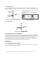
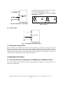
Fig.1 Circuit design 740.0060
1.2 Type 740.0065/65NA
The level switch type 740.0065 (fig. 2a) is reduced to a Reed miniswitch for low level AC/DC loads. The
type 740.0065NA is alternative - as shown in fig. 2b - fitted with two resistors (R
S
=1k, R
P
=10k) for usage
in NAMUR circuits.
Fig. 2a: Circuit 740.0065
Fig. 2b: Circuit 740.0065NA

PHÖNIX Messtechnik GmbH, Salzschlirferstr. 13, D-60386 Frankfurt/M., Germany, Tel: +49/69/416742 -20, Fax: -29
10
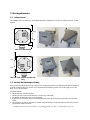
2 Mounting instructions
2.1 Delivery
The PHÖNIX type 740.0060/65 level switch can be delivered in the configurations shown below:
Fig. 3a: as delivered
Fig. 3b: with inverted switching di-
rection
2.2 Reversing the direction of switching
A reversal of the direction of switching involves the opposite switching function. Please note that the ca-
ble-gland is always directed downwards, as shown in fig. 3a and 3b.
Instruction:
• Remove the switch cover
•
Remove the safety access panel (type 740.0060 only)
• If necessary remove all connecting wires from the terminal
•
Take off screw, hexagon bolt and - for aluminium housing - the earth terminal
• After turning the circuit board 180° remount with screws , hexagon bolt and.- for aluminium housing-
the earth terminal.
• Reconnect the wires into the terminal
•
Put on the safety access panel (type 740.0060 only, very important !!)
OFF
OFF
ON
ON

PHÖNIX Messtechnik GmbH, Salzschlirferstr. 13, D-60386 Frankfurt/M., Germany, Tel: +49/69/416742 -20, Fax: -29
11
• Mount the bracket on the opposite side of the switch box. Use the second row of holes to keep the
distance.
• Remount the switch cover
3 Commissioning
Authorised skilled personnel only recommended to connect the electrical circuits.
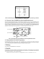
3.1 Mounting
The mounting of the switch is done by two col-
lars, which are supplied together with the switch,
as shown in Fig. 4. The cable gland is directed
downwards in any case. The switching point is
situated nearby the middle of the box. The heat
protection is optional for high temperature appli-
cations and is situated between the switch box
and the mounting bracket.
Fig. 4: The mounting to the tube is done by
two collars.
3.2 Electrical connections
3.2.1 Power switch
In AC applications the function is comparable to a mechanically operating switch and can be used in con-
junction with load relays, gate switches, solenoid valves etc. Because of the wiring (fig. 1) of the solid
state switch (Triac) a small permanent current will pass through C1 (47nF).
Fig. 5a: Connected as a power switch
Fig. 5b: Minimum load
3.2.2 Miniswitch
For this type of operation, the PHÖNIX type 740.0060 level switch is used as a normal mechanical
(REED) switch for low AC/DC-currents. The usual safety precautions for Reed switch contacts must be
observed (s. fig. 6b).
Last
housing
mounting screws
holder
optional
heat protection
mounting
bracket
collars
switching
point
M20x1
,
5

PHÖNIX Messtechnik GmbH, Salzschlirferstr. 13, D-60386 Frankfurt/M., Germany, Tel: +49/69/416742 -20, Fax: -29
12
Fig. 6a: Connected as a mini switch
For switch type 740.0060 at voltages >24 V remove
the resistor marked with R1 (s. fig. 1).
Please observe
limit values
(chapter 8) and
safety
precautions
(s. fig. 6b).
Fig. 6b: safety precautions for operation in low
DC/AC circuits.
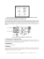
3.2.3 Namur switch
Fig. 7: Connecting of the Namur switch
3.3 Setting the switch position
Before starting-up, the bistable Reed contact must be properly set, in relation to the float in the level
gauge. This can be accomplished by using the control magnet (PHÖNIX part BG10XXXXMAKU, delivered
with liquid level gauges). This is moved up or down along the switch according to figs. 3a and 3b. The
switching function can be tested using an appropriate alarm or ohmmeter on the terminals 1 and 3. In this
case the system voltage, external wires must be disconnected !
4 Operating instructions
4.1 Two-step action with overlap with one PHÖNIX type 740.0060 level switch
Due to the Hysteresis of the bistable level switch type 740.0060 (see chapter 9) it can be used for a two-
step action of liquid levels.
low load
740.0065NA

PHÖNIX Messtechnik GmbH, Salzschlirferstr. 13, D-60386 Frankfurt/M., Germany, Tel: +49/69/416742 -20, Fax: -29
13
Fig. 8: A two-step action with a PHÖNIX level switch type 740.0060 utilising its hysteresis.
4.2 Using the type 740.0065NA in a hazardous area
The limit switch type 740.0065NA is designed for usage in NAMUR-circuits (s. fig. 2b). It consists only of
passive devices (switch and resistors), which allows - according to EN 50020 / VDE 0170 part 7 - the us-
age in hazardous areas zone 1 and 2, if they are part of a intrinsic save circuit and the maximum values of
voltage, current and power are not exceeded. The maximum of self heating is determined by R
S
(R
T
=
180°C/W) and the utilised power supply. If using the type 740.1061 (P
max
=51mW), the heating up is less
than 10°C.
Fig. 9: Usage of the type 740.0065NA in a hazardous area
4.3 Heat protection in high temperature
If medium temperature is more than 150°C (>260 °C for 740.0065NA) to reduce the heat radiation a heat
protection plate (Order-No.: 5745000159) has to be mounted between the tube and the switch. In this
case the switch must not be isolated together with the tube.
5 Maintenance
The switch is free of maintenance.
6 Warranty
We grant a guarantee period of 24 months for our products, provided that they have been handled and
operated under conditions described in the Operating Manual. In case of wear and spare parts we only
guarantee for failures in construction and material.
supply
Typ 740.0065N
Typ 740.0065N
safe
area
hazardous
area

PHÖNIX Messtechnik GmbH, Salzschlirferstr. 13, D-60386 Frankfurt/M., Germany, Tel: +49/69/416742 -20, Fax: -29
14
7 Disposal
The customer/enduser is obliged to take care for the disposal within the legal regulations.
8 Trouble shooting
Failure Problems Correction
no function wrong wiring, fuses, current supply check it
no bistable behaviour wrong mounting of the housing rise distance
the switch is always closed
(740.0060)
power switch: low current
Mini-switch: supply voltage > 24V
use it as a mini-switch
remove resistor R1
the switch opens spontane-
ously (miniswitch)
load is too high
temperature is too high
use an isolating switch amplifier
use a heat protection plate
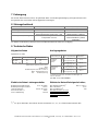
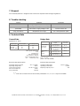
9 Technical Data
General Data Design Data
Hysteresis ca. [mm]
Cable gland downwards
IP65
Alu/Makrolon
with strap retainers
(Accesories s. page 2)
Makr.: 82x80x55/0,15 kg
Alu: 75x80x57/0,3 kg
Gauge-Type on basic pipe on heating jacket
710.104/2XX
710.100
710.110...160
6
10
15
15
20
25
Operating mode
M
a
k
r
.
A
l
u
M
a
k
r
.
A
l
u
max. temperature
of pipe
max. temp.
of housing
150 °C *)
at amb.Temp.85 °C
70 °C
Power switch
(Solid state
Triac-relay)
Small signal
switch
(Reed)
400 °C *)
at amb.Temp.55 °C
90 °C
150 °C *)
at amb.Temp.120 °C
500 °C *)
at amb.Temp.70 °C
120 °C
120 °C
*)Insulate between housing and pipe above
150 °C in pipe
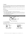
Electrical data power switch Electrical data miniswitch
Operating voltage nominal:
Operating voltage limit:
Load current nominal:
OFF-current (230 V~)
max. power limit:
24 V~ to 230V~
250 V~
24 mA~ to 2,5 A~
6 mA~
550 VA
Operating voltage limit:
Operating current limit:
Rupturing capacity UxI
max
:
400 V= / 230 V~
0,5 mA
5 W
-
1)
Take into account that none of the three parameters U
max
, I
max
, P
max
may be exceeded!
(
>260 °C for 740.0065NA)
Page is loading ...
-
 1
1
-
 2
2
-
 3
3
-
 4
4
-
 5
5
-
 6
6
-
 7
7
-
 8
8
-
 9
9
-
 10
10
-
 11
11
-
 12
12
-
 13
13
-
 14
14
-
 15
15
-
 16
16


Euphonix 740.0065 User manual
- Type
- User manual
- This manual is also suitable for
Ask a question and I''ll find the answer in the document
Finding information in a document is now easier with AI
in other languages
- Deutsch: Euphonix 740.0065 Benutzerhandbuch
Other documents
-
schmersal BN 20 Operating instructions
-
WIKA BLM tag:model:FLM Operating instructions
-
DigiTech MP 600-9000 DVI User manual
-
Beyerdynamic CA 4588 User manual
-
Kathrein EXD 1532 User manual
-
AKG AS8TC User manual
-
-
RCS BA-2120, 2240CP Owner's manual
-
Viessmann 5085 Owner's manual
-