Page is loading ...

911-566 REV. P 1
SHURFLO
®
3200 MACERATOR PUMP
INSTALLATION, OPERATION & REPAIR MANUAL
SHURFLO’s macerator pump is designed to empty marine and RV holding tanks of normal waste. It is also an excellent choice
for emptying fi sh boxes of scales and residual waste. A fl ow rate of up to 13 gallons per minute conveniently empties any tank
in minutes. The unique dual-cut blade design ensures waste is ground up thoroughly. The pump is self-priming to a fi ve foot lift
when impeller is wet, four foot lift when impeller is dry, but for optimum performance and life, it should be mounted as close to
the tank as possible. Marine pump out must be in proper discharge zones only. This macerator will not handle hard objects, rags,
or feminine napkins.
PRODUCT SPECIFICATIONS
Motor: Seamless can motor, 1/8 hp Thermally protected
Lead Wires: 14 GA
Fuse: See motor label for fuse size
Pump Type: Flexible Impeller
Duty Cycle: Intermittent duty only
Ports: Inlet: 1-1/2” hose barb &
1-1/2” NPT Male
Outlet: 1” hose barb
Impeller: Brandonite
®
Blade: 316 stainless “Double-cut”
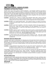
Dimensions: See drawing
Weight: 5 lbs.
Approvals: Ignition protected, ISO 8846, CE, and CSA, models available
Typical Flow: Dependent on fl uid viscosity (Chart below based on water)
HEAD FLOW GPM [LPM] MAX. DC AMPS
Ft. [m] 12 V 24 V 12 V 24 V
0 [0] 13 [49] 13 [49] 17 9
Max. Operating Head = 30 feet
1-1/2" Hose Barb
1" Hose Barb
3.8 [97.3]
3.5 [89.7]
4.8 [120.9]
10.8 [273.3]
3.6 [91.9]
2.0 [50.0]
2.9 [72.9]
2.3 [58.4]
1-1/2" NPT Male

2
ELECTRICAL CONNECTIONS
WARNING: If the pump is operated in an
area containing flammable vapors, the
wire leads must be joined by insulated
mechanical locking connectors. Loose
or inadequate wire connections can
spark, resulting in an explosion result-
ing in property damage, injury, or death.
All electrical installations should be
done by a qualified electrician.
❚ Pump must be protected with proper
size fuse as specified on the motor
label.
❚ Pump should be operated on a sepa-
rate circuit.
❚ Pump should be connected to properly
sized momentary switch. This prevents
pump from damage due to long periods
of dry run condition.
❚ Switch should be near pump. This will
allow operator to hear change in pump
sound when tank is empty.
AVERTISSEMENT: Si la pompe est
utilisée dans une zone contenant des
vapeurs inflammables, les fils doivent
être reliés par des raccords à verrouil-
lage mécanique isolés. Des raccorde-
ments de fils desserrés ou inadéquats
peuvent produire des étincelles et
provoquer une explosion entraînant des
dommages matériels, des blessures ou
la mort. Toutes les installations élec-
triques doivent être effectuées par un
électricien qualifié.
❚ La pompe doit être protégée par un
fusible de calibre approprié comme
précisé sur l’étiquette du moteur.
❚ La pompe devrait être utilisée sur un
circuit distinct.
❚ La pompe devrait être raccordée à un
interrupteur à rappel calibré correcte-
ment. Cela protège la pompe contre les
dommages attribuables à de longues
périodes de tournage à sec.
❚ L’interrupteur devrait se trouver
près de la pompe. Cela permettra à
l’utilisateur d’entendre un changement
dans le son de la pompe lorsque le
réservoir est vide.
NOTE: For proper operation motor must
rotate counterclockwise when viewed
from pump end.
PLUMBING CONNECTIONS
Pump should be mounted as near as possible to tank to minimize dry run. Pump is
self-priming to a five-foot lift when impeller is wet, four foot lift when impeller is dry.
Pump is more efficient if mounted near the holding tank. Installations should be
done by qualified marine tech.
INLET: Always install pump with a shut-off valve between pump and holding
tank.
Hose: Use 1-1/2” ID [non-collapsible vacuum rated] hose on inlet [suction]
side. Use stainless steel hose clamps on all sanitation connections.
Flange: To mount to 1-1/2” female flange, inlet barb must be cut off just before
threads. Seal threads and hand tighten.
WARNING: Any air leak on inlet side can cause pump to run dry and can damage
impeller and impeller housing. Check all inlet side connections, even those on deck
plates. All runs should be smooth with no kinks or sharp angles.
AVERTISSEMENT: Une fuite d’air sur le côté aspiration peut causer le tournage à
sec de la pompe et endommager la turbine et le boîtier de turbine. Vérifier tous les
raccordements sur le côté aspiration, même ceux sur les plaques de plateforme.
Tous les parcours doivent être lisses, sans tortillement ni angle aigus.
OUTLET: Use 1” minimum ID hose on discharge side of pump. Connect to thru
hull fitting above highest heeled point above waterline. Vented loop
installations must vent at least 10” above highest heeled point above
waterline. Use stainless steel hose clamps on all sanitation connec-
tions.
Operation: INTERMITTENT DUTY ONLY!
Pump switch must be near pump and tank so operator can hear pump running.
Make sure shut-off valve to pump and dump valve [if equipped] are both open. Turn
on momentary switch and pump out tank. When tank is empty, pump will get louder
with a high pitch sound. Immediately turn pump off, or damage to impeller and
housing will occur. Do not run pump dry for more than 15 – 20 seconds. Flush tank
and pump with water after each use. This macerator will handle normal waste, tis-
sues, cigarettes, fish scales, etc. It is not designed to handle large hard objects such
as large bones or fruit pits.
Periodic Maintenance and Storage: Flush with water after each use. Check wire
connections occasionally. After periods of non-use, impeller can stick. To loosen,
open rear shaft cover and turn motor shaft clockwise with a flat tip screwdriver.
Then replace shaft cover. For extended periods of non-use, pump impeller can be
lubricated by running a small amount of mineral oil through holding tank system.
12 Volt System Min. Wire Size (20 Amps)
Total Wire Length* 3% Drop 10% Drop
Feet [m] GA GA
1-10 [.3-3] #10 #16
11-20 [3.3-6] #8 #14
21-30 [6.4-9.1] #6 #12
30-60 [9.1-18.2] #4 #10
*length from power source to motor and
back to ground.
ELECTRICAL INSTALLATION CHECKLIST
√ Separate circuit from power source
√ Proper size momentary switch
mounted near pump
√ Proper wire size to length
√ Proper fuse size and type
√ Insulated wire connectors

3
MAINTENANCE
TURN OFF ALL POWER!
REAR END CAP/ MOTOR SHAFT SLOT ACCESS
Loosen end cap screws (17). Rotate shaft cover (16) to access slot on motor shaft.
PUMP DISASSEMBLY
Remove 3 cover screws (1). Remove cutter housing (2) and o-ring (3). Remove hex
nut (4) and cutter blades (5) & (6). It may be necessary to hold the motor shaft
steady. Insert a screwdriver into slot on motor shaft (see slot access above), or slip
a thin wrench (9/32” [7mm]) behind blades onto flat of motor shaft. Remove top wear
plate (7), gasket (8), impeller (9) and bottom wear plate (10). Remove impeller hous-
ing (11) and shaft seal (12). It is not necessary to remove slinger (13).
PUMP REASSEMBLY
Make sure slinger (13) is on shaft. Make sure shaft seal (12) is inserted properly into
rear of impeller housing (11). Slide impeller housing (11) onto motor shaft. Seat
bottom wear plate (10) into housing. Twist impeller (9) onto shaft and into housing
with a counterclockwise motion. Install gasket (8) and top wear plate (7). Install
cutter blades (6) & (5) with tab on bottom blade aligned with motor shaft flat. Secure
motor shaft with screwdriver or wrench (9/32”) [7mm] and tighten hex nut (4). Posi-
tion o-ring (3) and cutter housing (2) in place, and install cover screws (1).
MAINTENANCE TIP!
Loosen stuck impeller by turning motor
shaft clockwise from rear with a flat-
tipped screwdriver.
PARTS & KITS LIST
Item Description Qty.
1
Cover Screw
3
2
Cutter Housing
1
3
O-Ring
1
4
Hex Nut
1
5
Top Cutter
1
6
Bottom Cutter
1
7
Top Wear Plate
1
8
Gasket
1
9
Impeller
1
10
Bottom Wear Plate
1
11
Impeller Housing
1
12
Shaft Seal
1
13
Slinger
1
14
Motor Assembly
1
15
O-Ring
1
16
Rear End Shaft Cover
1
17
End Cap Screw
2
18
Baseplate Assembly
1
19
Hex Bolt
2
Kit Name Kit # Kit Item
Impeller
94-571-00 8,9
Pump Head
94-570-00
3, 7, 8, 9,
10, 11, 13
17
16
15
18
19
10
8
6
4
2
14
13
12
11
9
7
5
3
1

4
3545 HARBOR GATEWAY SOUTH, SUITE 103, COSTA MESA, CA 92626, (800) 854-3218 WWW.SHURFLO.COM
All Pentair trademarks and logos are owned by Pentair, Inc. All other brand or product names are trademarks or registered marks of their respective owners.
Because we are continuously improving our products and services, Pentair reserves the right to change specifications without prior notice.
Pentair is an equal opportunity employer.
911-566 Rev. P 03/16 ©Pentair, Inc. All Rights Reserved.
WARRANTY ON SHURFLO MACERATOR PUMPS
DO NOT SHIP MACERATOR PUMPS TO SHURFLO PUMP MANUFACTURING COM-
PANY! Under no circumstance will Macerator Pump returns be accepted at SHUR-
FLO Pump Co. for any reason. All returns must be taken to an authorized SHURFLO
dealer/marine store for replacement.
SHURFLO warrants to the original purchaser of its products (the “Purchaser”) that
such products will be free from defects in material and workmanship under normal
use for the period of one (1) year for all products except: accessories will be free
from defects in material and workmanship under normal use for the period of ninety
(90) days.
“Normal use” does not include use in excess of recommended pressures, vacuums
and temperatures, or use requiring handling of fluids not compatible with compo-
nent materials, as noted in SHURFLO product catalogs, technical literature, and
instructions. This warranty does not cover freight damage, freezing damage, normal
wear and tear, or damage caused by misapplication, fault, negligence, alterations, or
repair that affects the performance or reliability of the product.
THIS WARRANTY IS EXCLUSIVE. SHURFLO MAKES NO OTHER WARRANTY, EX-
PRESS OR IMPLIED, INCLUDING BUT NOT LIMITED TO ANY WARRANTY OF MER-
CHANTABILITY OR FITNESS FOR A PARTICULAR PURPOSE.
THIS IS THE EXCLUSIVE REMEDY FOR ANY BREACH OF WARRANTY. IN NO EVENT
SHALL SHURflo BE LIABLE FOR ANY INCIDENTAL OR CONSEQUENTIAL DAMAGES
OF ANY KIND, WHETHER FOR BREACH OF ANY WARRANTY, FOR NEGLIGENCE, ON
THE BASIS OF STRICT LIABILITY, OR OTHERWISE.
SHURFLO reserves the right to request a Material Safety Data sheet from the Pur-
chaser for any pump or product SHURFLO deems necessary. SHURFLO reserves the
right to “disposition as scrap” pumps or products returned which contain unknown
substances, or to charge for any and all costs incurred for chemical testing and
proper disposal of components containing unknown substances. SHURFLO requests
this in order to protect the environment and personnel from the hazards of handling
unknown substances.
SHURFLO may request additional information, and may require a sketch to illustrate
the problem.
Contact the closest factory with questions.
/