Quadra-Fire Mt. Vernon MTVERNON-CCR Owner's manual
- Category
- Stoves
- Type
- Owner's manual
This manual is also suitable for

R
www.quadrafire.com
7005-151D
December 22, 2006
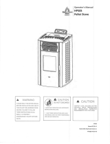
MT. VERNON PELLET STOVE
O-T L
Tested and
Listed by
Beaverton
Oregon USA
OMNI-Test Laboratories, Inc.
C
Owner’s Manual
Installation and Operation
MTVERNON-MBK
MTVERNON-CCR
MTVERNON-CLG
MTVERNON-PMH
MTVERNON-PMB
Models:
HOT! DO NOT TOUCH.
SEVERE BURNS MAY RESULT.
CLOTHING IGNITION MAY RESULT.
WARNING
• Keep children away.
• CAREFULLY SUPERVISE children in same room as
appliance.
• Alert children and adults to hazards of high
temperatures.
• Do NOT operate with protective barriers open or
removed.
• Keep clothing, furniture, draperies and other
combustibles away.
Glass and other surfaces are hot
during operation and cool down.
DO NOT DISCARD THIS MANUAL
CAUTION
• Important operating and
maintenance instruc-
tions included.
• Leave this manual with
party responsible for use
and operation.
• Read, understand and
follow these instruc-
tions for safe installa-
tion and operation.
DO NOT
DISCARD
WARNING
Please read this entire manual
before installation and use of this
pellet fuel-burning room heater.
Failure to follow these instructions
could result in property damage,
bodily injury or even death.
• Do not store or use gasoline or other flam-
mable vapors and liquids in the vicinity of this
or any other appliance.
• Do not overfire - If any external part starts
to glow, you are overfiring. Reduce feed rate.
Overfiring will void your warranty.
• Comply with all minimum clearances to com
-
bustibles as specified. Failure to comply may
cause house fire.
Check building codes prior to installation.
• Installation MUST comply with local, regional, state
and national codes and regulations.
• Consult local building, fire officials or authorities
having jurisdiction about restrictions, installation
inspection, and permits.
CAUTION
Tested and approved for wood pellets and shelled
field corn fuel only. Burning of any other type of fuel
voids your warranty.
CAUTION
f i r e - p a r t s . c o m

Page 2
7005-151D
December 22, 2006
R
Mt. Vernon Pellet Stove
R
R
Hearth & Home Technologies welcomes you to our tradi-
tion of excellence! In choosing a Quadra-Fire appliance,
you have our assurance of commitment to quality, durabil-
ity, and performance.
This commitment begins with our research of the market,
including ‘Voice of the Customer’ contacts, ensuring we
make products that will satisfy your needs. Our Research
and Development facility then employs the world’s most
advanced technology to achieve the optimum operation of
our stoves, inserts and fireplaces. And yet we are old-
fashioned when it comes to craftsmanship. Each unit is
meticulously fabricated and gold and nickel surfaces are
hand-finished for lasting beauty and enjoyment. Our pledge
to quality is completed as each model undergoes a quality
control inspection. From design, to fabrication, to shipping:
Our guarantee of quality is more than a word, it’s Quadra-
Fire tradition, and we proudly back this tradition with a Lim
-
ited Lifetime Warranty.
We wish you and your family many years of enjoyment in the
warmth and comfort of your hearth appliance. Thank you for
choosing Quadra-Fire.
With warm regards,
SAMPLE SERIAL NUMBER
/ SAFETY LABEL
LOCATION: Behind left
side curtain on outside of
hopper wall.
f i r e - p a r t s . c o m

R
R
R
December 22, 2006
7005-151D
Page 3
Mt. Vernon Pellet Stove
Section 1: Listing and Code Approvals
A. Appliance Certifications ......................4
B. Mobile Home Approved ......................4
C. Glass Specifications ............................4
D. Electrical Rating ..................................4
E. BTU & Efficiency Specifications ..........4
Section 2: Getting Started
A. Design, Installation & Location
Considerations ....................................5
B. Fire Safety ..........................................5
C. Tools & Supplies Needed ...................6
D. Measuring Standards .........................6
E. Inspect Appliance & Components ......6
Section 3: Dimensions & Clearances
A. Appliance Dimensions ........................7
B. Clearances to Combustibles ...............8
C. Hearth Requirements .........................9
Section 4: Vent Information
A. Chimney & Exhaust Connection .........10
B. Venting Termination Requirements ....10
C. Equivalent Feet of Pipe .......................11
D. Pipe Selection Chart ............................11
Section 5: Venting Systems
A. Alcove .................................................12
B. Through the Wall .................................13
C. Vertical ................................................14
D. Through the Wall & Vertical ................14
E. Masonry ..............................................15
F. Alternate Masonry ...............................15
Section 6: Mobile Home ..................................16
Section 7: Appliance Set-Up
A. Leg Leveling System ..........................17
B. Outside Air Kit .....................................17
C. Top Vent Adapter ................................18
D. Log Set Placement ..............................19
E. Thermostat Installation ........................19
Section 8: Operating Instructions
A. Fuel Size & Material ............................20
B. General Operation Information ...........20
C. Before Your First Fire .........................21
D. Fuel Adjustment Rod ..........................21
E. Starting Your First Fire ........................21
F. Fire Characteristics .............................21
G. Feed Rate Adjustment .......................21
H. Ignition Cycles ....................................22
I. Frequently Asked Questions ..............22
Section 9: Troubleshooting ............................23-25
Section 10: Maintaining & Servicing Appliance
A. General Maintenance & Cleaning .......26-28
B. Blower Replacement ...........................29
C. Igniter Replacement ............................30
D. Baffle Removal ....................................30
D. Glass Replacement .............................21
F. High Ash Fuel Content Maintenance ..31
Section 11: Reference Material
A. Component Functions ........................32-33
B. Component Locations .........................34
C. Exploded Drawings .............................35-36
D. Service Parts & Accessories ...............37-38
E. Warranty Policy ...................................39
F. Contact Information .............................40
TABLE OF CONTENTS
f i r e - p a r t s . c o m

Page 4
7005-151D
December 22, 2006
R
Mt. Vernon Pellet Stove
R
R
1
Listing and Code Approvals
A. Appliance Certification
C. Glass Specifications
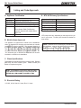
E. BTU & Efficiency Specifications
This appliance is equipped with 5mm ceramic glass. Replace
glass only with 5mm ceramic glass. Please contact your
dealer for replacement glass.
This appliance is approved for mobile home installations
when not installed in a sleeping room and when an outside
combustion air inlet is provided. The structural integrity of
the mobile home floor, ceiling, and walls must be maintained.
The appliance must be properly grounded to the frame of
the mobile home and use only listed pellet vent Class “L” or
“PL” connector pipe. A Quadra-Fire Outside Air Kit must be
installed in a mobile home installation.
B. Mobile Home Approved
NOTE: This installation must conform with local codes.
In the absence of local codes you must comply with the
ASTM E1509, (UM) 84-HUD, ULC/ORD-C-1482
D. Electrical Rating
115 VAC, 60 Hz, Start 4.1 Amps, Run 1.1 Amps
*BTU output will vary, depending on the brand of fuel you
use in your stove. Consult your Quadra-Fire dealer for
best results.
NOTE: Hearth & Home Technologies, manufacturer of
this appliance, reserves the right to alter its products,
their specifications and/or price without notice.
Emissions Rating 0.
.
7 grams/hr
*BTU Output 15,000 - 60,000 / hr
Heating Capacity up to 3,000 sq. ft.
Hopper Capacity 83 lbs
Fuel Wood Pellets or Shelled Corn
Shipping Weight
416 lbs
Model Mt. Vernon Pellet Stove
Laboratory OMNI Test Laboratories, Inc.
Report No. 061-S-56-2
Type Solid Fuel Room Heater/Pellet Type
Standard ASTM E1509 and ULC/ORD-C1482
Room Heater Pellet Fuel Burning
typeand (UM) 84-HUD, Mobile Home
Approved.
State Listing Colorado, Listed 09-13-05
f i r e - p a r t s . c o m

R
R
R
December 22, 2006
7005-151D
Page 5
Mt. Vernon Pellet Stove
2
Getting Started
A
.
Design, Installation & Location Considerations
1. Appliance Location
Consideration must be given to safety, convenience, traffic
flow, and the fact that the appliance will need a chimney and
chimney connector. It is a good idea to plan your installation
on paper, using exact measurements for clearances and floor
protection, before actually beginning the installation. If you
are not using an existing chimney, place the appliance where
there will be a clear passage for a factory-built listed chimney
through the ceiling and roof.
Check with your local building code agency before you begin
your installation. Be sure local building codes do not super-
sede UL specifications and always obtain a building permit
so that insurance protection benefits cannot be unexpectedly
cancelled. If any assistance is required during installation,
please contact your local dealer.
We recommend that a qualified building inspector and your
insurance company representative review your plans before
and after installation.
2. Thermostat Location
The thermostat’s location will have some effect on the
appliance’s operation. When the thermostat is located close
to the appliance, it may require a slightly higher temperature
setting to keep the rest of the house comfortable. If the
thermostat location is in an adjacent room or on a different
floor level, you will notice higher temperatures near the
appliance.
B. Fire Safety
Maintain the designated clearances to combustibles. Insu-
lation must not touch the chimney. You must maintain the
designated air space clearance around the chimney. This
space around a chimney is necessary to allow natural heat
removal from the area. Insulation in this space will cause
a heat buildup, which may ignite wood framing. NOTE:
Clearances may only be reduced by means approved
by the regulatory authority having jurisdiction.
To provide reasonable fire safety, the following should be
given serious consideration:
1. Install at least one smoke detector on each floor of
your home to ensure your safety. They should be
located away from the heating appliance and close
to the sleeping areas. Follow the smoke detector
manufacturer’s placement and installation instructions,
and be sure to maintain regularly.
2. A conveniently located Class A fire extinguisher
to contend with small fires resulting from burning
embers.
3. A practiced evacuation plan, consisting of at least two
escape routes.
4. A plan to deal with a hopper fire as follows:
In the event of a hopper fire:
a. Notify fire department
b. Prepare occupants for immediate evacuation.
c. Close all openings into the appliance.
d. While awaiting fire department, watch for ignition
of adjacent combustibles from overheated vent
pipe, hot embers or sparks from the chimney.
e. Pour a bucket of water into the appliance
hopper.
CAUTION
• Do NOT connect this unit to a chimney flue servicing
another appliance.
• Do NOT connect to any air distributon duct or system.
Fire Hazard.
WARNING
• Do not operate appliance before reading
and understanding operating instructions.
• Failure to operate appliance properly may
cause a house fire.
f i r e - p a r t s . c o m

Page 6
7005-151D
December 22, 2006
R
Mt. Vernon Pellet Stove
R
R
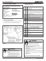
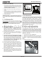
E. Inspect Appliance & Components and
Pre-Use Check List
Reciprocating Saw
Channel Locks
Hammer
Phillips Screwdriver
Tape Meausre
Plumb Line
Level
Framing Material
Hi-temp Caulking Material
Gloves
Safety Glasses
Framing Square
Electric Drill & Bits (1/4”)
1/4” Self-Tapping Screws
May also need:
Vent Support Straps
Venting Paint
Tools and building supplies normally required
for installation, unless installing into an existing
masonry fireplace:
C. Tools And Supplies Needed
Inspect appliance and components for
damage. Damaged parts may impair safe
operation.
WARNING
• Do NOT install damaged components.
• Do NOT install incomplete components.
• Do NOT install substitute components.
Report damaged parts to dealer.
• Installation and use of any damaged appliance.
• Modification of the appliance.
• Installation other than as instructed by Hearth & Home
Technologies.
• Installation and/or use of any component part not approved
by Hearth & Home Technologies.
• Operating appliance without fully assembling all
components.
• Operating appliance without legs attached (if supplied
with unit).
• Do NOT Overfire -
Or any such action that may cause a fire hazard.
WARNING
Hearth & Home Technologies disclaims any
responsibility for, and the warranty will be
voided by, the following actions:
D. Measuring Standards
1. Pipe measurements are from center line to center line.
2. Vertial terminations are measured to top of pipe.
Figure 6.1
1. Place the appliance in a location near the
final installation area and follow the proce-
dures below:
2. Open the appliance and remove all the parts
and articles packed inside the Component
Pack. Inspect all the parts and glass for ship-
ping damage. Contact your dealer if any irregu-
larities are noticed.
3. All safety warnings have been read and fol-
lowed.
4. This Owner’s Manual has been read.
5. Floor protection requirements have been met.
6. Venting is properly installed.
7. The proper clearances from the appliance and
chimney to combustible materials have been
met.
8. The masonry chimney is inspected by a profes-
sional and is clean, or the factory built metal
chimney is installed according to the manufac-
turer’s instructions and clearances.
9. The chimney meets the required minimum
height.
10.
All labels have been removed from the glass
door.
11. Plated surfaces have been wiped clean, if
applicable.
12. Thermostat or remote has been installed.
13. A power outlet is available nearby.
f i r e - p a r t s . c o m

R
R
R
December 22, 2006
7005-151D
Page 7
Mt. Vernon Pellet Stove
3
Dimensions and Clearances
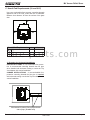
A. Appliance Dimensions
32-1/4"
(819mm)
28-1/8"
(714mm)
28-7/16"
(772mm)
14-1/16"
(357mm)
C
L
29-1/2"
(749mm)
15-1/4"
(387mm)
C
L
29-1/2"
(749mm)
17-1/2"
(445mm)
32-1/4"
(819mm)
32-1/8"
(816mm)
C
L
C
L
2-7/8" (73mm)
3" to 3" Adapter
1-5/8" (41mm)
3" to 6 " Adapter
20.0"
(508mm)
Figure 7.2- Front View
Figure 7.1 - Top View
Figure 7.3 -Side View
Figure 7.4 - Side View with Top Vent Adapter
f i r e - p a r t s . c o m

Page 8
7005-151D
December 22, 2006
R
Mt. Vernon Pellet Stove
R
R
Straight Back Against
Wall
Inches Millimeters
A
Back Wall to Appliance 2 51
B
Side Wall to Appliance 6 152
Corner Installation
Inches Millimeters
C
Walls to Appliance 2 51
Vertical Installation
Inches Millimeters
D
Back Wall to Flue Pipe 3 76
E
Side Wall to Appliance 6 152
F
Back Wall to Appliance 8 203
Installations with:
3 to 3 inch Top Vent Adapter and
3 to 6 inch Offset Adapter Kit
Corner Installation
Inches Millimeters
G
Walls to Appliance 2 51
H
Side Wall to Flue Pipe 3 76
Alcove Installation
Inches Millimeters
Minimum Alcove Height 43 1092
Minimum Alcove Side Wall
6 152
Minimum Alcove Width
40 1016
Maximum Alcove Depth
48 1219
Dimension to Corner
Inches Millimeters
I
Flue Center Line 10-3/8 264
J
Back of Top Vent Adapter 9-1/8 232
B. Clearances to Combustibles (UL and ULC)
D
E
F
A
B
Fire Risk.
Comply with all minimum clearances to
combustibles as specified.
WARNING
Failure to comply may cause house fire.
NOTE:
• Illustrations reflect typical installations and are FOR
DESIGN PURPOSES ONLY.
• Illustrations/diagrams are not drawn to scale.
• Actual installation may vary due to individual design
preference.
C
C
G
G
H
H
J
I
C
L
f i r e - p a r t s . c o m

R
R
R
December 22, 2006
7005-151D
Page 9
Mt. Vernon Pellet Stove
*L Exception for Horizontal Installations:
USA INSTALLATIONS: A
non-combustible floor protec-
tion is recommended extending beneath the flue pipe
when installed with horizontal venting or under the Top
Vent Adapter with vertical installation.
CANADA INSTALLATIONS: A
non-combustible floor
protection extending beneath the flue pipe is r
equired
with horizontal venting or under the Top Vent Adapter with
vertical installation.
Must extend 2 inches (51mm) beyond each
side of pipe (shaded area)
C. Hearth Pad Requirements (UL and ULC)
L*
K
K
M
Use a non-combustible floor protector, extending beneath
appliance and to the front, sides and rear as indicated.
Measure front distance “M” from the surface of the glass
door.
Hearth Pad Requirements
Inches Millimeters
K
Sides 2 51
L*
Back 2 51
M
Front 6 152
f i r e - p a r t s . c o m

Page 10
7005-151D
December 22, 2006
R
Mt. Vernon Pellet Stove
R
R
Do not terminate vent in any enclosed or semi-enclosed
area such as a carport, garage, attic, crawl space, under a
sun deck or porch, narrow walkway or closely fenced area,
or any location that can build up a concentration of fumes
such as a stairwell, covered breezeway, etc.
CAUTION
Vent surfaces get HOT, can cause burns
if touched. Non-combustible shielding or
guards may be required
WARNING
A. Chimney and Exhaust Connection
1. Chimney & Connector: Use 3 or 4 inch (76-102mm)
diameter type "L" or "PL" venting system. It can be
vented vertically or horizontally.
2. Mobile Home: Approved for all listed pellet vent. If
using the 3 inch (76mm) vertical Top Vent Adapter Kit
or the 3 to 6 inch (76-152mm) Top Vent Offset Adapter,
use listed double wall flue connector. A Quadra-Fire
Outside Air Kit must be used with manufactured home
installations.
3. Residential: The 3 inch (76mm) vertical Top Vent
Adapter Kit and the 3 to 6 inch (76-152mm) Top Vent
Offset Adapter are tested to use 24 gauge single wall
flue connector or listed double wall flue connector to
Class A listed metal chimneys, or masonry chimneys
meeting ICBO standards for solid fuel appliances.
4. INSTALL VENT AT CLEARANCES SPECIFIED BY THE
VENT MANUFACTURER.
5. Secure exhaust venting system to the appliance with at
least 3 screws. Also secure all connector pipe joints with
at least 3 screws through each joint.
NOTE: All pipe must be welded seam pipe whenever
possible. Seal pipe joints with high temperature silicone
(500°F [260°C] minimum rated only).
NOTE: If burning shelled field corn, you must use
approved venting specifically designed for corn. Follow
the instructions from the venting manufacturer.
Fire Hazard.
• Only LISTED venting components may be
used.
• NO OTHER vent components may be used.
Substitute or damaged vent components may
impair safe operation.
WARNING
B. Venting Termination Requirements
1. Termination must exhaust above air inlet elevation. It is
recommended that at least 60 inches (1524mm) of verti-
cal pipe be installed when appliance is vented directly
through a wall. This will create a natural draft, which will
help prevent the possibility of smoke or odor venting into
the home during a power outage. It will also keep exhaust
from causing a nuisance or hazard by exposing people or
shrubs to high temperatures. The safest and preferred
venting method is to extend the vent vertically through the
roof.
2. Distance from doors and opening windows, or gravity or
ventilation air inlets into building:
a. Not less than 48 inches (1219mm) below;
b. Not less than 48 inches (1219mm) horizontally from;
c. Not less than 12 inches (305mm) above.
3. Distance from permanently closed windows:
a. Not less than 12 inches (305mm) below; horizontally
from or above.
4. Distance between bottom of termination and grade should
be 24 inches (610mm) minimum. This is conditional upon
plants in the area, and nature of grade surface. The grade
surface must be a non-combustible material (i.e., rock, dirt).
The grade surface must not be lawn. Distance between
bottom of termination and public walkway should be 84
inches (2134mm) minimum.
5. Distance to combustible materials must be 24 inches
(610mm) minimum. This includes adjacent buildings,
fences, protruding parts of the structure, roof overhang,
plants and shrubs, etc.
6. Termination Cap Location (Home Electrical Service)
• Side-to-side clearance is to be the same as minimum
clearance to vinyl inside corners.
• Clearance of a termination cap below electrical service
shall be the same as minimum clearance to vinyl sof
-
fits.
• Clearance of a termination cap above electrical service
will be 12 inches (305mm) minimum.
• Location of the vent termination must not obstruct or
interfere with access to the electrical service.
4
Vent Information
f i r e - p a r t s . c o m

R
R
R
December 22, 2006
7005-151D
Page 11
Mt. Vernon Pellet Stove
Improper installation, adjustment, alteration, service or
maintenance can cause injury or property damage. Refer
to the owner’s information manual provided with this appli-
ance. For assistance or additional information consult a
qualified installer, service agency or your dealer.
WARNING
3 in. or 4 in. (76mm or 102mm) Diameter Pipe
Equivalent Pipe
Length In Feet
ALTITUDE IN THOUSANDS OF FEET
0
20
30
1 2 3 4 5 6 7 8 9 10
4 in. (102mm) Diameter Pipe Only
10
The chart will help you in determing proper vent-
ing size according to the equivalent feet of pipe
calcuated above and the altitude above sea level
of this installation. See Figure 11.2.
Locate the calculated equivalent feet of pipe on
the vertical left side of the chart. Move to the
right horizontally on the chart until you reach
your altitude above sea level.
If you fall below the diagonal line, 3 or 4 inch (76
to 102mm) pipe may be used. If it is anywhere
above the diagonal line, a 4 inch (102mm) diam
-
eter pipe is required.
The chart reveals that a 90° elbow is 5 times as
restrictive to the flow of exhaust gases under
positive pressure as 1 foot of horizontal pipe, and
a foot of horizontal pipe is twice as restrictive as
a foot of vertical pipe.
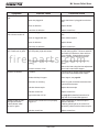
D. Pipe Selection Chart
The table below can help you calculate the equivalent feet
of pipe which is a method used to determine pellet vent size.
See Figure 11.1
C. Equivalent Feet of Pipe
2 ft.
2 ft.
3 ft.
2 ft.
Example of 3 Elbow-Rear Vent Termination Calculaton
Figure 11.1
Figure 11.2
Pellet Venting
Component
# of
Elbows
Feet of
Pipe
Multipled
By
Equivalent
Feet
Components
Equivalent Feet
90
o
Elbow or Tee
3 X 5 15
45
o
Elbow
X 3
Horizontal Pipe
7 X 1 7
Vertical Pipe
2 X 0.5 1
Total Equivalent Feet 23
Note: This is a generic example and is not
intended to represent any specific fuel type.
Fire Risk.
Do NOT pack insulation or other
combustibles between firestops.
• ALWAYS maintain specified clearances
around venting and firestop systems.
• Install firestops as specified.
Failure to keep insulation or other material
away from vent pipe may cause fire.
WARNING
CAUTION
Follow Chimney Connector Manufacturer’s Instructions
for Proper Installation.
ONLY use connector:
• Within the room, between appliance and ceiling or
wall.
Connector shall NOT pass through:
• Attic or roof space
• Closet or similar concealed space
• Floor or ceiling
Maintain minimum clearanes to combustibles
f i r e - p a r t s . c o m

Page 12
7005-151D
December 22, 2006
R
Mt. Vernon Pellet Stove
R
R
5
Venting Systems
NOTE:
• Illustrations reflect typical installations and are FOR
DESIGN PURPOSES ONLY
.
• Illustrations/diagrams are not drawn to scale.
• Actual installation may vary due to individual design
preference.
A. Alcove
Figure 12.1
*All minimums listed are to a combustible sur-
Minimum* Maximum
Inches Millimeters Inches Millimeters
A
Height 43 1092 n/a n/a
B
Width 40 1016 n/a n/a
C
Depth n/a n/a 48 1219
D
To Side Wall 6 152 n/a n/a
A
C
B
D
f i r e - p a r t s . c o m

R
R
R
December 22, 2006
7005-151D
Page 13
Mt. Vernon Pellet Stove
12 in.
(305mm)
Minimum
Non-combustible Hearth Pad
Wall
Thimble
Horizontal
Termination
Cap
2 in.
(51mm)
Minimum
6 in.
(152mm)
Minimum
From Glass
Straight Out
45 Degree
Wall
Thimble
Illustration shows venting going in both directions.
Choose which one is best for your installation.
2 in. (51mm)
Minimum
2 in.
(51mm)
Minimum
B. Through The Wall
Horizontal termination cap must be a minimum of 12 inches.
(305mm) from the wall. Approved for mobile home instal-
lations. Must use 3 or 4 inch (76-102mm) “L” or “PL” listed
pellet venting or listed double wall pipe and a Quadra-Fire
Outside Air Kit in mobile homes.
NOTE:
In Canada, where passage through a wall or partition of
combustible construction is desired, the installation shall
conform to CAN/CSA-B365
Figure 13.1
Figure 13.2
f i r e - p a r t s . c o m

Page 14
7005-151D
December 22, 2006
R
Mt. Vernon Pellet Stove
R
R
We recommend a minimum of 60 inches
(1524mm) vertical, however above the eave
is preferred.
Both installations are approved for mobile
home installations. Must use 3 or 4 inch (76
to 102mm) “L” or “PL” listed pellet venting or
listed double wall pipe and Quadra-Fire Out
-
side Air Kit in mobile homes. Single wall pipe
is approved for residential installations only.
C. Vertical
D. Through The Wall & Vertical
Firestop
Flashing
Rain Cap
6 in.
(152mm)
Min.
Non-combustible Hearth Pad
3 in. (76mm) Min.
Cleanout Cover
24 in. (610mm)
Minimum
Ceiling Support
6 in. (152mm) Flue
Connector
6 in. (152mm) Class A
Chimney Connector
Adapter
3 in. to 6 in.
(76-152mm)
Top Vent Kit
Non-combustible Hearth Pad
Cleanout Cover
Tee
Wall Thimble
Support Bracket
every 60 in. (1524mm)
24 in. (610mm) minimum
Rain Cap
Flashing
2 in. (51mm) minimum
6 in. (152mm)
minimum
Figure 14.1
Figure 14.2
f i r e - p a r t s . c o m

R
R
R
December 22, 2006
7005-151D
Page 15
Mt. Vernon Pellet Stove
Fire Hazard
Inspection of Chimney:
• Masonry chimney must be in good condition.
• Meets minimum standard of NFPA 211
• Factory-built chimney must be 6” (152mm) UL103 HT.
WARNING
E. Masonry
F.
Alternate Masonry
Non-combustible Hearth Pad
Airtight cleanout door
Sheathing
2 in. (51mm) minimum
Flashing
1 in. (25mm) clearance
1 in. (25mm) clearance
with firestop
6 in. (152mm)
minimum
Fireclay Flue Liner
with airspace
Concrete Cap
Figure 15.1
Figure 15.2
Non-combustible Hearth Pad
Airtight
Cleanout Door
Cleanout cover
Sheathing
3 in. (76mm) minimum
1 in. (25mm) clearance
Flashing
Fireclay flue
liner with airspace
Concrete Cap
1 in. (25mm) clearance
with firestop
6 in. (152mm)
minimum
f i r e - p a r t s . c o m

Page 16
7005-151D
December 22, 2006
R
Mt. Vernon Pellet Stove
R
R
6
Mobile Home
1. An outside air inlet must be provided for the combustion
air and must remain clear of leaves, debris, ice and/or
snow. It must be unrestricted while the appliance is
in use to prevent room air starvation which causes
smoke spillage. Smoke spillage can also set off smoke
alarms.
2. The combustion air duct system must be made of
metal. It must permit zero clearance to combustible
construction and prevent material from dropping into
the inlet or into the area beneath the dwelling and
contain a rodent screen.
3. The appliance must be secured to the mobile home
structure by bolting it to the floor (using lag bolts).
Use the same holes that secured the appliance to the
shipping pallet.
4. The appliance must be grounded with #8 solid copper
grounding wire or equivalent, terminated at each end
with an NEC approved grounding device.
5. Refer to Clearances to Combustibles and floor protec
-
tion requirements on pages 4 & 10 for listings to
combustibles and appropriate chimney systems.
6. Use silicone to create an effective vapor barrier at
the location where the chimney or other component
penetrates to the the exterior of the structure.
7. Follow the chimney manufacturer’s instructions when
installing the vent system for use in a mobile home.
8. Installation shall be in accordance with the Manufactur
-
ers Home & Safety Standard (HUD) CFR 3280, Part
24.
CAUTION
Maintain structural integrity of mobile home:
• Floor, wall, ceiling and/or roof.
Do NOT cut through:
• Floor joist, wall, studs or ceiling trusses.
• Any supporting material that would affect the structural
integrity.
Never install in a sleeping room.
WARNING
Installation must comply with Manufactured Home and
Safety Standard (HUD), CFR 3280, Part 24.
WARNING
You must use a Quadra-Fire Outside Air Kit
for installation in a mobile home.
A. Mobile Home Installation
Spark Arrestor Cap
Roof Flashing
Storm Collar
Joist Shield/Firestop
Double Wall
Pellet Vent
Figure 16.1
CAUTION
Never draw outside combustion air from:
• Wall, floor or ceiling cavity
• Enclosed space such as an attic or garage
f i r e - p a r t s . c o m

R
R
R
December 22, 2006
7005-151D
Page 17
Mt. Vernon Pellet Stove
7
Appliance Set-Up
A. Leg Leveling System
Figure 17.3 - Bolt fully extended
Figure 17.2
Figure 17.1
1. Thread Allen bolts through nuts until flush. Figure 17.1.
The
Allen bolts and nuts are included in the component
pack inside the stove firebox.
2. Slide assembled nuts and bolts into slots on legs with
the nuts on the bottom. Figure 17.2. Use a 5/32 in.
(3.96mm) Allen wrench to adjust legs up and down to
desired level. Figure 17.3
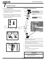
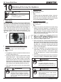
B. Outside Air Kit Instructions
Flex Hose
Hose Clamp
Collar Assembly
Trim Ring
Termination
Cap Assembly
Hose Clamp
Parts Included in Kit: 1 piece of
2 inch x 3 foot flex hose, 2 hose
clamps, 1 collar assembly,1 termi-
nation cap assembly, 1 trim ring,
12 screws.
1. Measure distance from floor to air vent opening in appli
-
ance and mark location on wall.
Use saw to cut opening in wall. Cut a 2-1/2 to 3 inch
(64-76mm) opening on inside wall and a 3 to 3-1/2 inch
(76-89mm) opening on outside of house.
2. Use hose clamp to secure flex pipe to collar assembly.
3. Slide trim ring over flex pipe and run pipe through wall.
4. Attach hose to outside termination cap with second
hose clamp.
5. Secure termination cap to outside surface.
6. Secure trim ring to interior wall.
Tools Needed: Phillips head-
screwdriver; wire cutters; hole
saw or jig saw.
Collar Assembly
CAUTION
Never draw outside combustion air from:
• Wall, floor or ceiling cavity
• Enclosed space such as an attic or garage
Figure 17.4
f i r e - p a r t s . c o m

Page 18
7005-151D
December 22, 2006
R
Mt. Vernon Pellet Stove
R
R
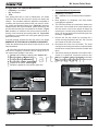
3 to 3 inch Top Vent Adapter
3 to 6 inch Top Vent Offset Adapter
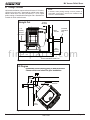
1.
Put a layer of high temperature silicone on the
3
inch (76mm) exhaust outlet. Figure 18.1
2. Slide the top vent adapter onto the rear exhaust
outlet and adjust the assembly to a vertical position.
Figure 18.1
3. Drill 4 holes with #26 drill bit (provided) into the
back of the appliance using the outer shield as
a pattern (make sure the assembly is vertical).
Figure 18.2
4. Install the 4 mounting screws.
5. Drill 2 holes with #26 drill bit through the rear
exhaust outlet using the 2 holes already in the short
horizontal pipe in the top vent adapter as a guide.
Install the 2 screws. Figure 18.1
6. Install the vent pipe into the top vent adapter (be
sure to silicone all joints).
7. To clean top vent adapter, open clean-out cover.
Figure 18.2.
C. Top Vent Adapter Installation
3 in. to 6 in.
Offset
Adapter
3 in. to 3 in.
Top Vent
Adapter
Use hole on each side
as drilling guide
Silicone
Rear Exhaust
Outlet
Drill holes in
back of stove
and secure with
4 screws, 2 on
each side
Clean Out Cover
Figure 18.2
Figure 18.1
Installing the Top Vent Adapter
D. Rear Vent and Rear Vent to Top Vent
Adapter Installation
Clean-Out Cover
Clean-Out Cover
Figure 18.3 - Rear Vent Adapter
Figure 18.4 - Rear to Top Vent Adapter - 90
o
1. Put a layer of high temperature silicone on the 3 inch
(76mm) exhaust outlet. Figure 18.1.
2. Slide the adapter onto the rear exhaust outlet and
adjust the assembly to the appropriate position.
3. Install the vent pipe into the adapter (be sure to
silicone all joints)
f i r e - p a r t s . c o m

R
R
R
December 22, 2006
7005-151D
Page 19
Mt. Vernon Pellet Stove
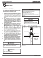
D. Optional Log Set Placement Instructions
1. Place the rear logs as shown. Be careful not to block
the drop tube in the back of the firebox where pellets
feed into the firepot. Figure 19.1
2. Place the large front log in the front moving it to the
right side. The exhaust exists on the left and that must
not be blocked. Figure 19.2
1. Place the top log over the other 3 logs. It must rest on
the logs in a stable position.
Figure 19.1
3 PIECE LOG SET INSTALLATION
OPTIONAL TOP LOG INSTALLATION
Figure 19.2
Feed Tube
Exhaust Exits on the Left
Do Not Block
Move to Right
Figure 19.3
CAUTION
Logs are FRAGILE. Use extreme care when handling or
cleaning logs.
NOTE:
Due to the abrasive nature of a pellet appliance fire, the
logs are not covered under warranty. Any placement varia-
tion other than shown here can cause excessive heat and
shall void the appliance warranty.
1. A 12 volt AC thermostat is required to operate this pellet
appliance. You may use the included wall mount thermo-
stat or purchase an optional programmable thermostat
or remote control. It is equipped with an adjustable
heat anticipator. The current rating is .05 amps. The
anticipator needs to be adjusted to the lowest setting
available.
2. When mounting a thermostat on a wall, be sure to follow
your thermostat installation instructions carefully.
NOTE: Thermostat must be mounted level for
accurate readings. The thermostat should be
mounted on an inside wall and not in direct line
with the appliance convection air.
NOTE: If the thermostat is located too close to the
appliance, you may need to set the temperature
setting slightly higher to maintain the desired
temperature in your home.
3. There is a 4 screw terminal block located on the back
lower left corner of the appliance directly above the power
cord inlet. The center 2 screws are for the thermostat
wires.
E. Thermostat Installation
TERMINAL BLOCK
CENTER 2 SCREWS FOR
THERMOSTAT WIRES
POWER OUTLET
FUSE
Fuse
Fuse
Figure 19.4
Shock hazard.
• Do NOT remove grounding prong from plug.
• Plug directly into properly grounded 3 prong
receptacle.
• Route cord away from appliance.
•
Do NOT route cord under or in front of appliance.
CAUTION
f i r e - p a r t s . c o m

Page 20
7005-151D
December 22, 2006
R
Mt. Vernon Pellet Stove
R
R
8
Operating Instructions
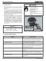
A. Fuel Size And Material
1. Wood Pellets
Fuel pellets are made from sawdust or wood by-products. If the
source material is hardwood, they can have a higher mineral
content, creating more ash. Fuels containing bark will also have
higher ash content. Minerals and other non-combustible materials
such as sand will turn into a hard, glass-like substance called
a clinker when heated to the extreme temperatures our firepot
reaches. This is what forms clinkers in the bottom of the firepot.
Trees from different areas will vary in mineral content. That is
why some fuels produce more clinkers than others. Pellets are
manufactured in either 1/4 inch or 5/16 inch (6-8mm) diameter and
should be no more than 1-1/2 inches (38mm) in length. Pellet
lengths may even vary by lot from the same manufacturer which
is why the feed rate may need to be adjusted occasionally. If you
burn pellets longer than 1-1/2 inches (38mm) you may have
an inconsistent fuel feed rate and/or missed ignitions.
Pellet fuel quality can greatly fluctuate. We recommend using
premium grade fuel with ash content less than 1%. Even in some
fuel labeled “premium” ash content can vary from bag to bag and
possibly exceed 1%. High ash fuel, or lack of maintenance, can
cause the firepot to fill up and thus create a potential for smoking,
sooting and possible hopper fires.
Always burn dry fuel. Burning fuel with high moisture content takes
heat from the fuel and tends to cool the appliance, robbing heat
from your home. Damp pellet fuel can clog the feed system.
We recommend that you buy fuel in multi-ton lots whenever
possible. Buying large quantities of fuel at once will greatly
reduce the number of times the feed adjustments will need to be
made. However, we do recommend trying various brands before
purchasing multi-ton lots to ensure your satisfaction.
2. Shelled Field Corn
Extensive factory and field testing has demonstrated shelled
field corn to be an efficient and very economical fuel. We
recommend the use of a 50-50 blend of corn and wood pellets.
The only change in operation is that the feed rate may require
a slight adjustment. The BTU output of the appliance varies
slightly compared to pellets, depending on the quality of the
corn used. In cases where it is acceptable for the appliance to
run full time, 100% corn will work after the fire has been started
using wood pellets.
B. General Operating Information
1. Thermostat Calls For Heat
The appliance is like most modern furnaces; when the
thermostat calls for heat, your appliance will
automatically
light and deliver heat. When the room is up to temperature
and the thermostat is satisfied, the red call light will go off
and the appliance will shut down.
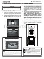
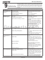
2. Heat Output Controls
This appliance is equipped with a heat output control
knob that has four settings or burn rates; low, medium,
high, and quad. The appliance will turn on and off as the
thermostat demands. When the thermostat calls for heat,
the appliance will start up at the burn rate for which it is
set. If the appliance is set at one of the lower settings, it
will run quieter but take longer to heat up an area than if
it were set at a higher burn rate. The quad setting is the
highest burn rate and produces the most heat with the
largest flame and burns at the highest rate of about seven
pounds of fuel per hour. Regardless of the burn rate,
when the area is warm enough to satisfy the thermostat,
the appliance will shut off.
RESET BUT TON
HEAT OUTPUT KNOB
MED
HIGH
QUAD
LOW
RESET
Figure 20.1
Fire Hazard.
Keep combustible materials, gasoline
and other flammable vapors and liquids
clear of appliance.
WARNING
• Do NOT store flammable materials in the appliance’s
vicinity.
• Do NOT use gasoline, lantern fuel, kerosene, charcoal
lighter fluid or similar liquids to start or “freshen up” a
fire in this heater.
• Keep all such liquids well away from the heater while
it is in use.
• Combustible materials may ignite.
Risk of Fire
WARNING
• High ash fuels, or lack of maintenance,
can cause the firepot to fill with ash
and clinker. If the firepot fills to the top,
immediately shut down the unit and clean.
• Failure to do so could result in smoking,
sooting and possible hopper fires.
f i r e - p a r t s . c o m
Page is loading ...
Page is loading ...
Page is loading ...
Page is loading ...
Page is loading ...
Page is loading ...
Page is loading ...
Page is loading ...
Page is loading ...
Page is loading ...
Page is loading ...
Page is loading ...
Page is loading ...
Page is loading ...
Page is loading ...
Page is loading ...
Page is loading ...
Page is loading ...
Page is loading ...
Page is loading ...
-
 1
1
-
 2
2
-
 3
3
-
 4
4
-
 5
5
-
 6
6
-
 7
7
-
 8
8
-
 9
9
-
 10
10
-
 11
11
-
 12
12
-
 13
13
-
 14
14
-
 15
15
-
 16
16
-
 17
17
-
 18
18
-
 19
19
-
 20
20
-
 21
21
-
 22
22
-
 23
23
-
 24
24
-
 25
25
-
 26
26
-
 27
27
-
 28
28
-
 29
29
-
 30
30
-
 31
31
-
 32
32
-
 33
33
-
 34
34
-
 35
35
-
 36
36
-
 37
37
-
 38
38
-
 39
39
-
 40
40


Quadra-Fire Mt. Vernon MTVERNON-CCR Owner's manual
- Category
- Stoves
- Type
- Owner's manual
- This manual is also suitable for
Ask a question and I''ll find the answer in the document
Finding information in a document is now easier with AI
Related papers
-
Quadra-Fire TPVNT-7 Pellet Adapter Installation guide
-
Aladdin Quadra-Fire 1100-I User manual
-
-
-
-
-
-
-
United States Stove 24A Operating instructions
-
Other documents
-
Cavaliere SV168B2-30 Installation guide
-
Hearth and Home Technologies PS35 User manual
-
US Stove HS40DLTTT1 Installation guide
-
 ComfortBilt HP50-White User manual
-
Sub-Zero 826747 Installation guide
-
Kozyheat Olivia Owner's manual
-
River of Goods 19701 Installation guide
-
 Ricardo Trading 02000-79-063-03 Installation guide
-
Lennox International Inc. WINSLOW PS40 User manual
-
Osburn OP00048 User guide

