Page is loading ...

BOS1901-KIT
User Guide
BOS1901CDK01.2 © All rights reserved 2019 Boréas Technologies Inc 1
BOS1901 Development Kit
1 Features
• Plug and play development kit to experience
piezo haptic feedback
• Low-power BOS1901 integrated circuit, high
voltage driver with digital interface
• Simple power interface for development via
USB port
• Standard USB audio to prototype haptic
effects in MATLAB®, Python®, Audacity® and
many other softwares
1
• Fully embeddable modular software driver
• Easy generation of high-voltage waveforms
up to 190 Vpp
• Two breakable miniature PCBs with BOS1901
drivers
• Standard commercial piezo actuators
included in the Kit:
o Starter Set: TDK PowerHap™ 1204
2
lateral
o Premium Set: TDK PowerHap™ 1204
lateral, 0904 lateral, 0909 square, Midé
Technology PPA-2014 bending.
2 Description
The BOS1901-KIT is a Development Kit to help
users who want to get familiarized with the
BOS1901 Piezo Haptic Driver IC.
The USB powered kit appears as an USB Audio
device for the computer, which allows the rapid
generation of waveforms using existing audio
software like Audacity® for haptic prototyping.
Each breakable miniature PCB gives access to all
signals allowing the user to experiment with the
BOS1901 using a development platform of his/her
choice.
Standard commercial piezo actuators are provided
as a starting point to begin experiencing with
haptic feedback.
Table 1: Ordering information
PRODUCT
DESCRIPTION
BOS1901-KIT-A
Premium Set with Four Actuators
BOS1901-KIT-B
Starter Set with One Actuator
For details see section 2
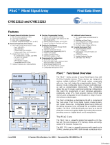
Figure 1: Simplified BOS1901-KIT diagram
1
MATLAB® is registered trademark of The MathWorks, Inc.
Python® is a registered trademark of the PSF
2
PowerHap™ is a trademark of TDK Corporation
Audacity® is a registered trademark of Dominic Mazzoni
BOS1901
breakable PCB
Channel B
BOS1901
breakable PCB
Channel A
SPI
Microcontroller
External
PSU
USB
SWD
DIP
Switches

BOS1901-KIT
User Guide
BOS1901CDK01.2 © All rights reserved 2019 Boréas Technologies Inc 2
3 Quick-Start guide
3.1 What's in the Box
The BOS1901-KIT is currently available in two distinct packages: Premium Set and Starter Set. The
following tables show the content of each set.
Table 2: Premium Set BOS1901-KIT-A development kit content
#
ITEM
DESCRIPTION
REFERENCE
1
Evaluation PCB
BOS1901 Evaluation PCB
2
USB Cable
Cable to connect the evaluation PCB to a computer
Stewart Connector part number SC-2AMK001F
3
TDK Piezo Actuator
TDK Mini PowerHap™ 1204H018V060 (4.5G) Actuator
Ordering : Z63000Z2910Z 1Z 39
Capacitance : 0.42 μF
Dim : 12.0 x 4.0 x 1.8 mm
4
TDK Piezo Actuator
TDK Mini PowerHap™ 0904H014V060 (3.0G) Actuator
Ordering Z63000Z2910Z 1Z 41
Capacitance : 0.32 μF
Dim : 9.0 x 3.75 x 1.4 mm
5
TDK Piezo Actuator
TDK PowerHap™ 0909H011V060 (2.5G) Actuator
Ordering: B54103H2020A001 (Z63000Z2910Z 1Z 2)
Capacitance : 0.85 μF
Dim : 9.0 x 9.0 x 0.55 mm
6
Midé Piezo Actuator
Midé PPA-2014 (S233-H5FR-1107XB) Flex with
4-to-2 connector,
Clamp
M3 x 0.3 mm thread hex nuts
6 mm low-profile socket head screws.
Refer to section 4.2.3 for clamp assembly instructions.
7
Power Connector
Connector and cable for external power supply
connection (refer to section 4.1.1)
JST Sales America Inc. part numbers PHR-2 and
ASPHSPH24K51

BOS1901-KIT
User Guide
BOS1901CDK01.2 © All rights reserved 2019 Boréas Technologies Inc 3
Table 3: Starter Set BOS1901-KIT-B development kit content
#
ITEM
DESCRIPTION
REFERENCE
1
Evaluation PCB
BOS1901 Evaluation PCB
2
USB Cable
Cable to connect the evaluation PCB to a computer
Stewart Connector part number SC-2AMK001F
3
TDK Piezo Actuator
TDK Mini PowerHap™ 1204H018V060 (4.5G) Actuator
Ordering : Z63000Z2910Z 1Z 39
Capacitance : 0.42 μF
Dim : 12.0 x 4.0 x 1.8 mm
4
Power Connector
Connector and cable for external power supply
connection (refer to section 4.1.1)
JST Sales America Inc. part numbers PHR-2 and
ASPHSPH24K51

BOS1901-KIT
User Guide
BOS1901CDK01.2 © All rights reserved 2019 Boréas Technologies Inc 4
3.2 PCB Overview
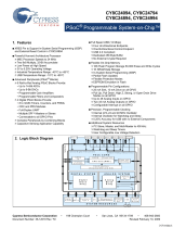
Figure 2: BOS1901-KIT Evaluation PCB overview
3.3 Quick-Start Procedure
1. Refer to sections 4.1 for jumper options and 4.2 for switch settings to insure the evaluation PCB
is in the intended settings.
2. Connect the selected actuator to channel A on P2A connector (refer to sections 4.2 and 4.4).
We recommend securing the actuator on a flat surface using electrical insulation tape to avoid
touching exposed connections and improve the feedback sensation.
3. Connect the evaluation PCB to a computer using the included USB cable, then wait for LED D1
(green) to light up and LED D2 (red) to turn and stay off, after the firmware identification
sequence (see section 6.1).
4. Push the sensor with a finger to feel the feedback. Enhance the feedback experience by
changing DIP switch settings (refer to section 4.2). With switches 5, 6 and 7 all set to OFF the
"click" might be too subtle. Turn all switches 5, 6 and 7 to ON and then push the piezo again;
the feeling should be clearer. Try various settings for switches 5 to 7 and see how it affects the
feedback.
5. Plug the piezo into channel B and set SW3 to ON and SW4 to ON. Gradually apply pressure on
the piezo, 3 events can be felt: 1 click, then a stronger click, and then a buzz. If it is difficult to
distinguish all 3 events, set SW7 OFF to decrease the sensitivity.
6. Using the Audacity® software (refer to section 5.2), select a waveform to play on the actuator.
USB
USR
RST
µCPU
DIP switch
BAT
Power
2018
www.boreas.ca
Designed and
Made in Canada
BOS1901-KIT_V2.3
BOS1901
BOS1901
HV+HV-
VDD
HV+HV-
VDD
SB2
SB3
SB1A
SB1B
1 8
D1 D2
VBUS
GND
MISO
VIO
MOSI
SCK
CS
VBUS
GND
MISO
VIO
MOSI
SCK
CS
GND
VDD
XRES
SWDCLK
SWDIO
ON
OFF
CHANNEL A
CHANNEL B
P2A
P2B

BOS1901-KIT
User Guide
BOS1901CDK01.2 © All rights reserved 2019 Boréas Technologies Inc 5
4 Hardware
4.1 Jumper Options
The BOS1901-KIT is provided by default with jumpers SB2, SB3 and SB1X set to operate from USB power,
UPI mode off.
Table 4: Jumper options
Function
Shorts
HW
USB Power
UPI OFF
(default)
SB2
SB3
SB1x
USB Power
UPI ON*
SB2
SB3
SB1x
BAT Power
UPI OFF
SB2
SB3
SB1x
BAT Power
UPI ON*
SB2
SB3
SB1x
* Refer to section 4.1.2 for more details and limitations.
4.1.1 Using BAT Power (external power supply connection)
From default state:
1. Remove power to the evaluation PCB by unplugging the USB cable.
2. Cut junction of SB3 jumper. Verify it is well-disconnected using a multimeter.
3. Put a solder joint on SB2. Verify the new connection using a multimeter.
4. Optional, solder a capacitor on C19 if additional decoupling is required on VBUS node.
5. Plug the USB cable to the evaluation PCB for power and communication to the microcontroller
section.
6. Apply an external DC source ranging from 3 V to 5 V on connector P5 using the provided power
connector (item # 5 in Table 2: Premium Set (BOS1901-KIT-A) development kit content).
7. Push and release "RST" button (S2), then wait for green LED to light up and for red LED to turn
and stay off, after the firmware identification sequence (see section 6.1).
Note: the "USR" button (S1) has reserved usage on the current firmware.
SB2
BOS1901
BAT
USB
SB3
VBUS
VDD
SB1x

BOS1901-KIT
User Guide
BOS1901CDK01.2 © All rights reserved 2019 Boréas Technologies Inc 6
4.1.2 Using UPI Feature
WARNING - With UPI enabled, the energy recovery feature of the BOS1901 will accumulate energy on
C1A/C1B capacitor, causing VDD voltage to increase. The user should make sure that VDD voltage
never exceeds the 5.5 V limit otherwise it may permanently damage the BOS1901. For instance, due
to its larger capacitance, it is not recommended to use the PowerHap™ 2.5G actuator with 5 V supply
and UPI feature ON. When using this feature with piezo devices other than those provided in the kit,
make sure to size C1A/C1B accordingly. Please refer to BOS1901 datasheet section 6.2.10 for more
details.
From default state:
1. Remove power to the evaluation PCB by unplugging the USB cable.
2. Remove solder joint on one or both SB1X, depending on the choice of UPI configuration. Verify
the disconnection using a multimeter.
3. Plug the USB cable to the evaluation PCB, wait for green LED to light up and for red LED to turn
and stay off, after the firmware identification sequence (see section 6.1).
4.2 Piezo Actuators
One TDK actuator is provided with the BOS1901-KIT Starter Set and four with the Premium Set, one from
Midé and the others from TDK.
4.2.1 Midé Actuator
Midé PPA-2014 Flex piezo actuator specifications:
Type
Bender
Polarity
None, can be connected on either side using the provided 4-to-2
connector
Range
Full-scale -95 V to +95 V, use with switch SW1 at "ON" position
(refer to section 4.3)
4.2.2 TDK Actuator
TDK PowerHap™ 2.5G piezo actuator specifications:
Type
Cymbal design
Polarity
Red wire on "HV+" terminal
Black wire on "HV-" terminal
Range
Unipolar -10 V to +60 V, use with switch SW1 at "OFF" position
(refer to section 4.3)
TDK Mini PowerHap™ 1204H018V060 specifications:
Type
Cymbal design
Polarity
Red wire on "HV+" terminal
Black wire on "HV-" terminal
Range
Unipolar -10 V to +60 V, use with switch SW1 at "OFF" position
(refer to section 4.3)

BOS1901-KIT
User Guide
BOS1901CDK01.2 © All rights reserved 2019 Boréas Technologies Inc 7
TDK Mini PowerHap™ 0904H014V060 specifications:
Type
Cymbal design
Polarity
Red wire on "HV+" terminal
Black wire on "HV-" terminal
Range
Unipolar -10 V to +60 V, use with switch SW1 at "OFF" position
(refer to section 4.3)
It is of utmost importance to not use the TDK PowerHap™ actuators in Full-scale mode as it can get
damaged unless the waveform is properly designed to limit the output voltage between -10 V and
+60 V. Example waveforms are provided on Boréas website (www.boreas.ca/bos1901-kit).
Refer to section 4.4.2 for a special output configuration, in which two TDK actuators can be connected
on a single BOS1901 circuit:
- "Load 1" with red wire connected to "HV+" and black wire on "VDD"
- "Load 2" with red wire connected to "HV-" and black wire on "VDD"
- Use of Unipolar mode with output voltage limited to +60 V (SW1 set to OFF)
- Toggle SW2 to single ended mode (ON)

BOS1901-KIT
User Guide
BOS1901CDK01.2 © All rights reserved 2019 Boréas Technologies Inc 8
4.2.3 Midé Actuator Clamp Assembly Instructions
The Midé actuator must be assembled the provided clamp to be operated properly. Follow the
instructions below to assemble the clamp on the actuator.
1. Take Midé actuator, black clamp, screw and
nuts, and 4-to-2 connector.
2. Separate the clamp in two parts. Place the
actuator inside the clamp with the rigid actuator
part on the side with 5 holes and the flexible
ribbon and blue connector on the side with only 2
holes. Make sure the middle hole of the actuator
is aligned with the middle hole of the clamp.
3. Use 3 screws and 3 nuts to fix the assembly.
4. To feel the actuator feedback, just touch the
rigid part. To activate the click detection, hold the
clamp in place and gently press on the actuator
rigid part. If the click feedback is not felt, flip the
entire assembly upside down.
Figure 3 Midé actuator clamp assembly instructions

BOS1901-KIT
User Guide
BOS1901CDK01.2 © All rights reserved 2019 Boréas Technologies Inc 9
4.3 DIP Switch Settings
The evaluation PCB is provided by default with S3 DIP Switch set to Unipolar operation with only
Channel A enabled. It is recommended to toggle these switches only while not playing waveforms.
Table 5: S3 DIP switch settings
DEFAULT
SWITCH
OFF
ON
OFF
SW1
Unipolar (-10 V/+60 V)
Full-scale (-95 V/+95 V)
OFF
SW2
Differential out config*
Single ended config*
OFF
SW3
Only channel A ON
Both channels ON
OFF
SW4
Press-release feedback
on channel B
Multipress feedback on
channel B
OFF
SW5
100 Hz feedback
180 Hz feedback
OFF
SW6
75 % amplitude feedback
100 % amplitude feedback
OFF
SW7
Low sensitivity feedback
High sensitivity feedback
OFF
SW8
Not used
Not used
* Refer to section 4.4 for more details on output configurations
SW1 The output ranges listed for SW1 settings are for full amplitude input signal, for example -1 to
+1 when using Audacity® software (refer to section 5.2). When using Midé PPA-2014 Flex piezo
actuator, set SW1 to ON. When using TDK PowerHap™ piezo actuator, set SW1 to OFF.
More precisely, this switch sets the maximum and minimum values allowable for the selected
range. It does not affect the gain and offset conversion between the input signal and the output
voltage. If the requested voltage is out the range, the firmware will clip the signal to the limits
of the range. Therefore, a single conversion equation is used for the same voltage in both
ranges. The relation between the input signal value and the output voltage is:
𝑆𝑖𝑔𝑛𝑎𝑙 =
𝑉𝑜𝑙𝑡𝑎𝑔𝑒
95 𝑉
Thus signals of +1, -1 and 0 correspond to 95 V, -95 V and 0 V respectively. To generate a 60 V
output, the signal should be 60 V/95 V = 0.631.
SW2 Refer to section 4.4 for configuration details. Sensing is not possible in single-ended
configuration.
SW3 SW3 determines how many channels are active. Set SW3 to OFF to activate only channel A. Set
SW3 to ON to activate both channels. When a channel is activated it can sense pressure and
give feedback, and it can play waveforms.
SW4 When both channels are active (SW3 is ON), set SW4 to OFF to have both channels feedback a
single click. Setting SW4 to ON will maintain channel A to feedback single clicks but channel B
will give three feedback response levels depending on the exerted pressure. A low-level

BOS1901-KIT
User Guide
BOS1901CDK01.2 © All rights reserved 2019 Boréas Technologies Inc 10
pressure triggers a single light click, medium pressure triggers a stronger click, and a high
pressure triggers a longer feedback.
SW5 SW5 sets the frequency of the feedback response when the actuator is pressed and released.
SW6 SW6 sets the amplitude level of the feedback response. Setting SW6 to ON will provide a
stronger response than setting it to OFF. SW6 has an effect only in press-release mode.
SW7 SW7 sets the sensitivity level for feedback. Setting SW7 to ON will require less pressure to
trigger the feedback.
SW8 SW8 is not used in the current firmware. It could be used in firmware created by the user.
Setting SW5, SW6 and SW7 to ON will maximize the feedback response.

BOS1901-KIT
User Guide
BOS1901CDK01.2 © All rights reserved 2019 Boréas Technologies Inc 11
4.4 Output Configuration Options
With the two-terminal differential output, two outputs configurations are possible to drive a piezo.
4.4.1 Differential Output Configuration
The typical output configuration is the differential output, refer to Figure 4. The piezo-element is driven
with one terminal connected to "HV+" and the other connected to "HV-". This configuration can achieve
a differential output voltage of 190 Vpp in Full-scale mode.
Figure 4: Two-terminal differential output configuration
4.4.2 Single-Ended Output Configuration
The single ended output configuration allows to drive up to two different piezo elements, see Figure 5.
A piezo element is driven with one terminal connected to "HV+" or "HV-" and the other connected to
"VDD". This configuration can achieve a single ended output voltage of 95 V. Only one piezo element can
be driven at a time based on signal polarity.
Figure 5: Two-terminal single-ended output configuration
RM
RP
VDD
VBUS
SCLK
CS
SDI
SDO
VDDIO
REG
SW
HV
OUT+
OUT -
GND
R
sense
L
1
C
VDD
C
HV
SPI
3.0 V to 5.5 V
C
REG
C
VDDIO
BOS1901
PUMP
C
PUMP
190 V
pp
(HV+)
(HV-)
Load
RM
RP
VDD
VBUS
SCLK
CS
SDI
SDO
VDDIO
REG
SW
HV
OUT+
OUT -
GND
R
sense
L
1
C
VDD
C
HV
SPI
3.0 V to 5.5 V
Load 1
C
REG
C
VDDIO
BOS1901
PUMP
C
PUMP
Load 2
95 V
p
95 V
p
(HV+)
(HV-)
(VDD)

BOS1901-KIT
User Guide
BOS1901CDK01.2 © All rights reserved 2019 Boréas Technologies Inc 12
4.5 Breakable Units
The use of the breakable units with custom-made firmware is done at the user's own risk of causing
damage beyond repair to the BOS1901 circuit. Boréas Technologies will not be held responsible.
Each channel is on a breakable PCB unit that can be used alone with a user-preferred development
platform. The available signals are:
- GND 0 V reference
- VDD Main power supply for the BOS1901 (from 3 V to 5 V)
- VIO Digital IO power supply (set to SPI signals voltage level, between 1.8 V and 5 V)
- MISO SPI Master In/Slave Out signal
- MOSI SPI Master Out/Slave In signal
- SCK SPI Clock signal
- CS SPI Chip Select signal (active low)
Refer to BOS1901 datasheet for a complete description on how to use and program the circuit.

BOS1901-KIT
User Guide
BOS1901CDK01.2 © All rights reserved 2019 Boréas Technologies Inc 13
5 Software
5.1 Software Installation Procedure
Please follow the Audacity® installation procedure. The software is free of use and can be found at:
https://www.audacityteam.org/download/.
Refer to https://www.audacityteam.org/about/license/ for the terms of GNU General Public License
(GPL) for Audacity® use.
5.2 Software Operation
The evaluation PCB appears as a speaker to the computer. The following operation example is made
using Audacity® software, but the use of any other software is also possible. Make sure the USB audio
firmware is installed on the evaluation PCB, refer to section 6.1 for firmware installation/update
procedure.
1. Connect the evaluation PCB with the USB cable, wait for green LED to light up and for red LED
to turn and stay off, after the firmware identification sequence (see section 6.1).
2. Start Audacity®, then select "File/Open…" to load "Audacity project - BOS1901-KIT.aup" file
available for download on Boréas website.
3. Select the appropriate Audio Host (see Figure 6):
• For Windows: select "Windows Direct Sound"
• For MAC OS X: select "Audio Core"
• Fox Linux: select "ALSA"
4. Select "Cypress Digital Audio" as the Playback Device (see Figure 6).
5. Press play button to start the default 100 Hz sine waveform, which will play for 5 seconds.
Figure 6: Audacity® software interface

BOS1901-KIT
User Guide
BOS1901CDK01.2 © All rights reserved 2019 Boréas Technologies Inc 14
6. The balance between channels A and B can be changed using the "L/R" dial in the "Audio Track"
field, "L" corresponding to channel A, "R" to channel B. The gain can also be changed with "-/+"
dial, but beware of positive gains that may cause output clipping.
7. To generate another kind of waveform, change its frequency or amplitude, go to the
"Generate/Tone…" menu. For Square and Sawtooth, it is possible the software will calculate
points based on an 8 kHz filter, therefore distorting the output waveform. To offset the
waveform, an effect called "DC offset" may be applied, but it must be installed first. Instructions
on how to install plugins are given on the Audacity® website.
8. Existing or generated .wav files can be played with Audacity®, loaded with the "File/Open…"
dialog.
9. If starting a new project, make sure to use a Project Rate at 8 kHz (lower left corner field).
10. For other Audacity® features, please refer to the software help.

BOS1901-KIT
User Guide
BOS1901CDK01.2 © All rights reserved 2019 Boréas Technologies Inc 15
6 Firmware
6.1 Identifying the Firmware Revision Number
Since firmware revision 2.2, when powering up the development kit, both LEDs will show the firmware
revision number and then the IC revision.
After the 10-second bootload window while both LEDs are on (see next section), the green and red LEDs
flash to indicate the firmware revision number. For a firmware revision X.Y with major revision X and
minor revision Y, the green LED will flash X times and then the red LED will flash Y times. This sequence
is repeated for a beta revision.
Then both LEDs are lit a short while as some initialization is performed, and then ICs are identified. Green
LED will flash to indicate channel A BOS1901 IC revision, and red LED will flash to indicate channel B
BOS1901 IC revision. For each channel, the LEDs will flash 1, 2 or 3 times to indicate the IC for that
channel is of revision A, B or C respectively.
6.2 Firmware Installation/Update Procedure
The BOS1901-KIT is provided out-of-the box with a firmware for use as an USB Audio device.
This firmware can be changed and/or updated using the USBBootloaderHost.exe application available
on Boréas website. The procedure is the following:
1. Load the appropriate *.cyacd file using the "Load File" button.
2. Press and release the "RST" button on the evaluation PCB . When the "USB HID State" field reads
"Connected", press on "Program" button. Note that the evaluation PCB will stay connected for
only 10 seconds; the "Program" button must be pressed within that time. After this delay, red
LED turns off, the firmware identification sequence occurs and then the evaluation PCB enters
normal operation. If the "USB HID State" field does not read "Connected", press on "RST" button
and try again.
3. Wait for installation/update to finish, the "Status Log" field will inform of a successful firmware
installation.
4. Once the installation is complete, LEDs will go through the firmware identification sequence
given in the previous section, and end with green LED on and red LED off. If red LED does not
turn off, wait a couple of seconds then press and release "RST" again.

BOS1901-KIT
User Guide
BOS1901CDK01.2 © All rights reserved 2019 Boréas Technologies Inc 16
Figure 7: USBBootloaderHost.exe interface for firmware installation/update

BOS1901-KIT
User Guide
BOS1901CDK01.2 © All rights reserved 2019 Boréas Technologies Inc 17
6.3 Firmware Modification - Using PSoC® Creator™
3
Firmware modification by the user will not be supported by Boréas Technologies. It is done at the
user's own risk of causing damage beyond repair to the BOS1901. This section only presents a starting
point for any user who may want to modify the firmware. A careful read of the BOS1901 datasheet is
strongly recommended before doing so.
The firmware source code is available for download on Boréas website. PSoC® Creator™ IDE is available
for download at http://www.cypress.com/products/psoc-creator-integrated-design-environment-ide.
The procedure for first firmware compilation is:
1. Start PSoC® Creator™, then go to "File/Open/Project" and select the file "PSoCCreator.cywrk"
(make sure to start with the latest project file).
2. In the "Workspace Explorer", right-click on "Project 'USBFS_Bootloader'" then choose "Build
USBFS_Bootloader".
3. In the "Workspace Explorer", right-click on "Project 'BOS1901_Test'" then choose "Build
BOS1901_Test".
4. The compiled firmware BOS1901_Test.cyacd will be in the folder:
Project name\BOS9101_Test.cydsn\CortexM3\ARM_GCC_541\Debug\
5. Update the firmware using the procedure presented in section 6.2.
After any code modification, repeat steps 3 to 5 to test.
It is highly recommended to use a Cypress MiniProg3 (CY8KIT-002) when modifying the source code. This
inexpensive kit allows to program the PSoC® microcontroller directly from PSoC® Creator™ through the
SWD connector on the board. It also enables to enter debug mode and save valuable time in producing
bug-free code.
Board resources can be used in modified code. DIP switch 8 is not used and can be programmed by the
user. Other DIP switches, USR button, and LEDs can all be reprogrammed if the associated code is
adjusted accordingly.
Unused PSoC® I/Os can be activated to expand user-specific application code; wires can be soldered on
them if necessary. PSoC® internal components such as ADCs and EEPROM memory may also be used.
3
PSoC® is a registered trademark of Cypress Semiconductor Corporation
PSoC® Creator™ is a trademark of Cypress Semiconductor Corporation

BOS1901-KIT
User Guide
BOS1901CDK01.2 © All rights reserved 2019 Boréas Technologies Inc 18
6.4 Adjusting Sensing Feedback Parameters via Firmware Modification
The BOS1901-KIT is provided out-of-the box with a firmware that allows sensing feedback to be
experienced (see section 3.3). S3 DIP Switches SW4 to SW7 can be used to toggle the sensing feedback
parameters between preset values (see section 4.3). Finer adjustment of the sensing feedback
parameters is done by firmware modification or using the GUI available for download on our website,
refer to section 7 for more details. The following sections explain how to change the settings of each DIP
Switch state by modifying the firmware source code.
6.4.1 Sensing Feedback Amplitude
Do not put values higher than 1.0 for any of those variables or it will permanently damage the piezo.
These variables only have an effect when in TDK mode (SW1 OFF).
1. In PSoC® Creator™, go to project "BOS1901_Test", then go to folder "Header Files" and open
file "sensing_button_data.h".
2. Edit the #define variables values in section "Amplitude variables".
• LOW_AMP_MULTIPLICATOR changes the high-low amplitude ratio.
• HIGH_AMP_PRESS_FEEDBACK_TDK_CIRC changes the press feedback intensity.
- When SW6 is ON, the feedback amplitude is set to
HIGH_AMP_PRESS_FEEDBACK_TDK_CIRC.
- When SW6 is OFF, the feedback amplitude is set to LOW_AMP_MULTIPLICATOR times
HIGH_AMP_PRESS_FEEDBACK_TDK_CIRC.
• HIGH_AMP_RELEASE_FEEDBACK_TDK_CIRC changes the release feedback intensity.
- When SW6 is ON, the feedback amplitude is set to
HIGH_AMP_RELEASE_FEEDBACK_TDK_CIRC.
- When SW6 is OFF, the feedback amplitude is set to LOW_AMP_MULTIPLICATOR times
HIGH_AMP_RELEASE_FEEDBACK_TDK_CIRC.
3. Save and build the project, and then upload the new firmware as explained in section 6.2 or
using a MiniProg3.
6.4.2 Sensing Feedback Frequency
Do not put values higher than 300 for any of those variables or it will permanently damage the piezo.
1. In PSoC® Creator™, go to project "BOS1901_Test", then go to folder "Header Files" and open
file "sensing_button_data.h".
2. Edit the #define variables values in section "Frequency variables".
• SENSING_FEEDBACK_FREQ_DEFAULT_LOW changes the low feedback signal frequency
(SW5 is OFF).
• SENSING_FEEDBACK_FREQ_DEFAULT_HIGH changes the high feedback signal frequency
(SW5 is ON).
3. Save and build the project, and then upload the new firmware as explained in section 6.2 or
using a MiniProg3.

BOS1901-KIT
User Guide
BOS1901CDK01.2 © All rights reserved 2019 Boréas Technologies Inc 19
6.4.3 Sensing Threshold
These variables only have an effect when in TDK mode (SW1 OFF).
1. In PSoC® Creator™, go to project "BOS1901_Test", then go to folder "Header Files" and open
file "sensing_button_data.h"
2. Edit the #define variables values in section "Threshold variables".
• HS_TRESH_TDK_CIRC changes the high sensitivity threshold (SW7 is OFF).
• LS_TRESH_TDK_CIRC changes the low sensitivity threshold (SW7 is ON).
3. Save and build the project, and then upload the new firmware as explained in section 6.2 or
using a MiniProg3.
6.4.4 Response Type
1. In PSoC® Creator™, go to project "BOS1901_Test", then go to folder "Header Files" and open file
"sensing_button_data.h"
2. Edit the #define variables values in section "Response type".
• RESPONSE_TYPE_CLICK_PRD changes number of sine wave period on single click feedback
(press-release feedback on both channels, low and medium pressure of multipress
feedback on channel B).
• RESPONSE_TYPE_LONG_PRD changes number of sine wave period on long feedback (high
pressure of multipress feedback on channel B).
3. Save and build the project, and then upload the new firmware as explained in section 6.2 or
using a MiniProg3.
Note: Since firmware v2.3, the “USR” button is used to return all parameters programmed using
BOS1901-KIT Controller GUI software to their default value.

BOS1901-KIT
User Guide
BOS1901CDK01.2 © All rights reserved 2019 Boréas Technologies Inc 20
7 BOS1901-KIT Controller (GUI)
BOS1901-KIT Controller is a graphical user interface intended to ease evaluation of the BOS1901 IC using
BOS1901-KIT development kit. Using this application, all functionalities specific to the BOS1901 IC and
BOS1901-KIT are configurable, giving the user direct control over the behaviour of the driven
piezoelectric actuator, without the need to modify the firmware source code. It is intended as a first step
in evaluating the BOS1901 IC, before getting into system-specific SPI interfacing.
The GUI installer is available for download on Boréas website. Any advices on the installation procedure
and on how to use it will be found in the BOS1901-KIT Controller (GUI) – User Guide also provided on
the website.
Figure 8: BOS1901-KIT Controller GUI – Main Window
/