Shivaki SSH-P076DC User manual
- Category
- Split-system air conditioners
- Type
- User manual
This manual is also suitable for

WALL MOUNTED SPLIT-TYPE AIR CONDITIONERS
CONTENTS
1. IMPORTANT NOTICE ···································2
2. OPERATION DETAILS ·······························3
3. WIRING DIAGRAM ············· 10
4. EXPLOSION VIEW ····························11
5. PARTS LIST ·············12
Models
SSH-P076DC/SRH-P076DC
SSH-P096DC/SRH-P096DC
SSH-P126DC/SRH-P126DC
SSH-P186DC/SRH-P186DC
OB207t-1qxp 25/9/97 8:51 PM Page 1
SHIVAKI
SERVICE MANUAL No.TE150119

IMPORTANT NOTICE
This service manual is intended for use by individuals possessing adequate
backgrounds of electrical, electronic and mechanical experience. Any
attempt to repair the appliance may result in personal injury and property
damage. The manufacturer or seller cannot be responsible for the
interpretation of this information, nor can it assume any liability in
connection with its use.
The information, specifications and parameter are subject to change due to
technical modification or improvement without any prior notice. The
accurate specifications are presented on the nameplate label.
How to order spare parts
To have your order filled promptly and correctly, please furnish the
following information:
1. Model No. with Indoor or Outdoor
2. No. in the Explosion View
3. Part Name
4. The quantity you ordered
TCL Air Conditioner Service ManualTCL Air Conditioner Service ManualTCL Air Conditioner Service Manual
Air Conditioner Service Manual
2

3
Air Conditioner Service Manual
Note: Each mode and relevant function will be further specified in following pages.
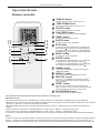
Operation Details
Remote controller
1
2
4
3
5
6
7
8MODE button
ON/OFF button
To select the mode of operation.
ECO button
In cooling mode,press this button ,the temperature
will increase 2 on the base of setting temperature:
In heating mode, press this button, the temperature
will decrease 2 on the base of setting temperature.
To switch the conditioner on and off.
FAN SPEED button
To select the fan speed of auto/low/mid/high.
TIMER button
To set automatic switching-on/off.
TEMP UP button
Increase the temperature or time by 1 unit.
SLEEP button
To activate the function SLEEP .
TEMP DOWN button
Decrease the temperature or time by 1 unit.
Remote Control
The remote controller is not presetting as Cooling Only Air Conditioner or Heat Pump by manufacturer.
Each time after the remote controller replace batteries or is energized, the arrowhead will flashes on the front of
Heat or Cool on LCD of the remote controller.
User can preset the remote controller type depending on the air conditioner type you have purchased as
follows:
Press any button when the arrowhead flashes on the front of Cool , Cooling Only is set.
Press any button when the arrowhead flashes on the front of Heat , Heat Pump is set.
If you don t press any button within 10 seconds, the remote controller is preset as Heat Pump automatically.
Note :
If the air conditioner you purchased is a Cooling Only one, but you preset the remote controller as Heat Pump, it
doesn t bring any matter. But if the air conditioner you purchased is a Heat Pump one, and you preset the
remote controller as Cooling Only, then you CAN NOT preset the Heating operation with the remote controller.
9
SUPER button
In cooling mode, press this button, the unit will give
the maximum cooling temperature with 16
In heating mode, press this button, the unit will give
the maximum heating temperature with 31 .
10
9
SWING button
To activate or deactivate of the movement of the
DEFLECTORS .
12
DISPLAY button
LED display (if present).To switch on/off the
13
HEALTHY button
To switch - on /off HEALTHY funtion.It is a button
which controls the ionizer or plasma generator only
for inverter type.
14
9
RESET button
This button is useless for wall-mounted type.
When you press "3D", the horizontal and vertical
vanes will swing together at the same time.
14
3
4
2
1
9
5
6
7
8
10
12
13 16
16
9
ANTI MILDEW button
To activate the function ANTI-MILDEW.
10
14
16

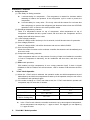
Air Conditioner Service Manual
Electronic Controller
1. Safety Protection
(1) Time Delay for Safety protection
z 3 minutes delay for compressor ---The compressor is ceased for 3minutes before
restarting to balance the pressure in the refrigeration cycle in order to protect the
compressor.
z 2 minutes delay for 4-way valve---The 4-way valve will be ceased for 2 minutes late
after compressor to prevent the refrigerant-gas abnormal noise when the HEATING
operation is OFF or switch to the other operation mode.
(2) Discharge temperature protection
There is a temperature sensor on top of compressor, when temperature on top of
compressor exceeded the limit, system control will shut down the compressor and the
display board will show the error code.
(3) lower voltage protection
When AC voltage ≤158V and keep it for 10 seconds, unit will be shut down for protection.
(4) Over voltage protection
When AC voltage ≥260V, unit will be shut down and recover while AC≤255V.
(5) Over current protection
When the current of outdoor unit is overload, controller shut down the unit immediately and
show error code.
(6) Compressor abnormity protection
When compressor start on or in the process of running, if there is no feedback to controller
or load of compressor is abnormity, the air conditioner will shut down, and show error
code.
(7) IPM module protection
IPM module has high temperature & over current protection itself, if there is signal
feedback to IPM, the outdoor unit will shut down, LED on outdoor PCB will show the error
code.
2. “I Feel” Mode Operation
(1) When the “I Feel” mode is selected, the operation mode and initial temperature set are
determined by the initial room temperature at start-up of the operation except to turn off the
air conditioner and operates it again.
(2) If the mode is change to “I Feel” from other mode, the “I Feel” mode doesn’t operate until
compressor stop for more than 3 minutes.
Mode Initial Room Temperature Initial Set Temperature
COOLING RT≥26℃23℃
DRY 26℃>RT≥20℃RT-2℃
HEATING for Heat Pump
FAN for Cooling Only RT<20℃-
z In the “I Feel” mode, when the controller receives the up or down signal of temperature,
the set temperature can adjust by 1℃ upper or lower. The biggest you can adjust by
2℃ upper or lower.
3. “COOLING” Mode Operation
4

(1) Compressor frequency control
According to difference room temperature and set temperature(δt = RT-ST), running
frequency of compressor is controlled by electronic controller. When room temperature is much
higher than set temperature, compressor will start at a high frequency, and as room temperature
goes down, compressor running frequency will go down. When room temperature is lower than set
temperature, compressor will run at very low frequency. In general, unit will change its running
frequency according toδt to make room temperature closing to set temperature.
(2) Outdoor temperature affects running frequency of compressor
Outdoor temperature affect compressor’s running frequency. Difference inlet temperature of
outdoor unit is adapted by difference compressor running frequency. While outdoor temperature is
about 30℃, the compressor will run in high frequency.
If unit run in “cooling” mode and outdoor temperature is less than -1℃,controller will shut down
compressor and show error code, while the ambient temperature is over 0℃, the compressor will
run automatically.
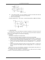
(3) Auto fan control in cooling mode
In cooling mode (include cooling in “I feel” mode), fan speed is determined by δt, as the
following diagram:
℃
1.5
1.0
3.0
3.5
δt come down
high fan
δt come up
midium fan
low fan
RT-ST
4. “DRY” Mode Operation
(1) The system for DRY operation used the same refrigerant circle as the cooling one.
(2) When the system operates in DRY mode, at first it operates in cooling mode at 16℃ or
18℃ for 3 minutes. After that, the system will operate in cooling mode with lowest fan
speed, meanwhile the set temperature (ST) is “RT-2℃” which means that the ST is room
temperature at then minus 2. During the course of this mode, the fan speed set operation
and room temperature set are restricted, except the vane motor adjusting.
5. “HEATING” Mode Operation (available for Heat Pump only)
(1) Frequency control
The same as the frequency control in cooing mode, running frequency of compressor is
controlled by controller. Unit change its running frequency according to δt to make room
temperature closing to the set temperature.
(2) Indoor fan motor control
1. Cold Air
Prevention Control
z The function is intended to prevent cold air from being discharged when the heating
operation starts or when defrosting.
z The indoor fan speed will be controlled as following.
5
Air Conditioner Service Manual

Air Conditioner Service Manual
25℃
37℃
33℃
30℃
22℃
34℃
z In the heating operation, if the air conditioner is turned off, the indoor fan motor will
run most for 30 seconds since the stop of compressor.
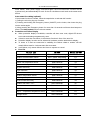
2. Auto fan control (heating)
In heating mode(include in “I feel” mode) , fan speed is determined by δt, as the following:
℃
1.5
1.0
3.0
3.5
δt com e dow n
high fan
δt com e up
midium fan
low fa n
RT-ST
(3) 4-way valve control
In heating mode, 4-way valve will power on ahead of compressor for 5 seconds, and cut off
for 2 minutes later than compressor’s stop. 4-way valve will not power off unless the machine is
switched off, mode changed or on the process of defrosting.
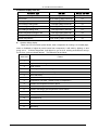
(4) Defrosting
Defrosting is controlled by the microprocessor.
When one of the following conditions is satisfied, unit will come into defrosting:
a. Outdoor heat exchanger Temperature (OPT) is continuously less than 3℃ while the unit
runs for more than 40 minutes, and OPT is keeping under -6℃ for more than 3 minutes.
b. Outdoor heat exchanger Temperature (OPT) is continuously less than 3℃ meanwhile
the unit runs for more than 80 minutes, and OPT is keeping under -4℃ for more than 3
minutes.
c. Outdoor heat exchanger Temperature (OPT) is continuously less than 3℃ while the unit
runs for more than 120 minutes, and OPT is keeping below -2℃ for more than 3
minutes.
Before the air con come into defrosting, compressor running frequency drop down to a
lower frequency firstly, then the compressor shuts down.
In defrosting, the max. frequency of compressor is F9 (a little less than the highest
frequency ). In this period all protection function are avaliable.
6

Air Conditioner Service Manual
com pressor
4-w ay valve
outdoor fan m otor
≤10m
ON
OFF
ON
OFF
ON
OFF
20s 10s 20s 10s
In defrosting, LED showing by winking.
Come into or out of defrosting, indoor fan motor speed is the same as Cold Air Prevention
Control.
One of the following conditions is satisfied, unit come out of defrosting and shift to heating
mode:
a. Outdoor coil Temperature (OPT) ≥15℃
b. Defrost time keep time for more than 10 minutes.
(5) Indoor exchanger overheat protection
When Indoor exchanger Temperature(IPT) is higher than 55 ℃, unit come into indoor
exchanger overheat protection. Compressor drop its frequency toward to F1 level until IPT≤52
℃; If IPT≤52℃ and keep for 5 minutes , control system don’t limit running frequency.
If IPT>62℃, control system shut down compressor, and recover when IPT drop less than 50℃.
6. “SLEEP” mode
When the SLEEP button is pressed, the SLEEP mode is selected as following:
z The indoor fan speed is set at low speed, the power lamp and the sleep lamp is on, the
display of temperature will be close after 5 minutes.
z When selecting COOLING/DRY operation with SLEEP mode, the set temperature will be
raised by 1℃ 1 hour later and by 2℃ 2 hour later.
z When selecting HEATING operation with SLEEP mode, the set temperature will be dropped
by 1℃ 1 hour later and 2℃ 2hour later.
z After the System operates in SLEEP mode for 8 hours, it will stop automatically.
7. EMERGENCY Operation
When the EMERGENCY Operation switch is pressed once, COOLING mode is selected and if
in 3 seconds the EMERGENCY Operation switch is pressed again, mode is selected. Then
pressed once again, the unit is switch off.
When the remote controller is missing, has failed or the batteries run down, press the
EMERGENCY Operation switch on the front of the indoor unit. The unit will start.
The first 30 minutes of operation will be the test run operation. The operation is for servicing.
The indoor fan runs at high speed and the system is in continuous operation. The thermostat is
ON and the timer is reset to normal.
After 30 minutes of test run operation the system shifts to AUTO COOLING/HEATING mode,
and the indoor fan runs in automatic speed. The operation continues unit the EMERGENCY
operation switch is pressed or a button on the remote controller is pressed, the normal
operation will start.
NOTE: Do not press the EMERGEMCY Operation switch during normal operation.
8. AUTO-RESTART Function (Option)
1. When air conditioner is operating in one mode, all of its operation data, such as working
mode and temperature of setup would be memorized into IC by main PCB. If power cuts due to
7

Air Conditioner Service Manual
some reason, when power supply come back again, the AUTO-RESTART function will set
synchronously and automatically to work. So the air conditioner would work at the same mode
before.
Auto-restart Pre-setting (optional):
If Auto-restart function is needed, follow the steps below to activate this function:
1) Pulling the air-con's plug out of socket.
2) Pressing and holding the Emergency button (ON/OFF) on the indoor, then insert the plug
into the socket again.
3) Keep pressing the Emergency button for more than 10 seconds until three short beeps are
heard. The Auto-restart function has been started.
9. Protection and Failure Display
z When protection display is available, controller will show error code, digital LED shows
error code and setting temperature by turns.
z If there is more than one failure, it will show at first that in front of the error list.
z Protection display function can be selected in hardware, and the default don’t display;
z To insure of in and out communist is credibility, the failures relate to outdoor unit will
remain failure state for 2 minutes max after recovered.
z In all failures, only sensor failures don’t have to repower to cancel.
z Error list
Failure type LED CODE DIGITAL LED CODE
In and out communication failure RUN、TIMER –both winking E0
Outdoor communication failure RUN、TIMER –both winking EC
Outdoor sensor RUN-1 time/8s E1
Indoor coil temperature sensor RUN-2 times /8s E2
Outdoor coil temperature sensor RUN-3 times /8s E3
System abnormity RUN-4 times /8s E4
Type mismatch RUN-5 times /8s E5
Indoor fan motor RUN-6 times /8s E6
Outdoor temperature sensor RUN-7 times /8s E7
Discharge temperature sensor RUN-8 times /8s E8
Invert module abnormity RUN-9 times /8s E9
Outdoor fan motor(DC)RUN-10 times /8s EF
Current sensor RUN-11 times /8s EA
EEPROM failure RUN-12 times /8s EE
Top of compressor temperature switch RUN-13 times /8s EP
Voltage sensor RUN-14 times /8s EU
8

Air Conditioner Service Manual
Protection display code list:
Protection type LED CODE DIGITAL LED CODE
higher or lower voltage RUN-winking,TIMER-1 time/8s P1
Over current RUN- winking,TIMER-2 times /8s P2
Discharge temperature RUN- winking,TIMER-4 times /8s P4
Over cooling in cooling mode RUN-light,TIMER-5 times /8s P5
Over heating in cooling mode RUN- light,TIMER-6 times /8s P6
Over heating in heating mode RUN- light,TIMER-7 times /8s P7
Outdoor temperature too high or low RUN- light,TIMER-8 times /8s P8
Drive protection(Overload) RUN- winking,TIMER-9 times/8s P9
Module self protection RUN- winking,TIMER-10 times/8s P0
z Outdoor failure display
There is a LED on outdoor power board, when compressor is running; it is normally light;
when no feedback of signal to power board from compressor, it will wink by lighting 1s and
going out 1s. If failures happened, it will light 0.5s, go out 0.5s, winking several times and go
out 3s for a cycle to indicate failures. The failure list is the follow:
Wink time Failure
1 IPM protection
2 higher or lower voltage
3 Over current
4 Discharge temperature too high
5 Outdoor coil temperature too high
6 Drive abnormity
7 Communication abnormity with indoor unit
8 Compressor over heat(switch on top of compressor)
9 Outdoor air temperature sensor failure
10 Outdoor coil temperature sensor failure
11 Outdoor discharge pipe temperature sensor failure
12 Voltage sensor failure
13 Current sensor failure
14 IPM abnormity
15 Outdoor communication abnormity
16 DC fan motor no feedback
17 defrosting
9

Air Conditioner Service Manual
10
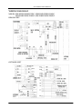
WIRING DIAGRAM
MODEL: SSH-P076DC/SRH-P076DC, SSH-P096DC/SRH-P096DC
SSH-P126DC/SRH-P126DC, SSH-P186DC/SRH-P186DC
INDOOR UNIT:
OUTDOOR UNIT

Air Conditioner Service Manual
11
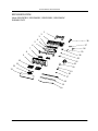
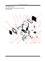
EXPLOSION VIEW
Mode: SSH-P076DC, SSH-P096DC, SSH-P126DC, SSH-P186DC
INDOOR UNIT:
15
6
14
11
13 12
8
10
9
7
1
5432
19
18
17
16
23
24
21
20
22
26
25
27
28

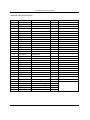
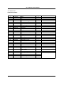
INDOOR UNIT:SSH-P076DC
No. Part No. Part Name Q’ty Remark
1 1080030003 Installation plate 1
2 1080320807AC Base 1
3 1070020017AA indoor fan 1
4 1070100010 Bearing Mount 1
5 211230474 Evaporator 1
6 1070251611AB Water Drainage Assembly 1
7 1070321035 Vertical Vane Assembly 2
8 1070251372AE Face frame 1
9 1070321022AC Screw cover 2
10 1070250106 Air filter 2
11 1070252211 Display PCB Box 1
12 1090321196 Display PCB 1
13 210706140 Front Panel 1
14 1170120044 Power supply cord 1
15 1070251837AE vane 1
16 1070110011 Drainage hose 1
17 1070040004 Cable clamp 1
18 1170200042 Terminal 1
19 1070250109 Terminal fixing board 1
20 210900001AE main PCB 1
21 1070320113 Electrical box 1
22 1073010501 Sensor holder 1
23 1170020011 vane motor 1
24 1170030047 Indoor motor 1
25 1070320111 Indoor motor cover 1
26 1170240001 transformer 1
27 1170230001 indoor sensor assembly 1
28 1080320818AB In And Out Pipe Fixer 1
29 1090090001AL Remote controller 1
30 1070060003 Remote controller supporter 1
31 1190060827ACM Indoor cartoon 1
32 211310246 Left foaming 1
33 211310247 Right foaming 1
Air Conditioner Service Manual
Not shown in explosion view
12

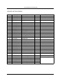
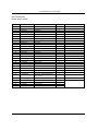
INDOOR UNIT:SSH-P096DC
No. Part No. Part Name Q’ty Remark
1 1080030003 Installation plate 1
2 1080320807AC Base 1
3 1070020017AA indoor fan 1
4 1070100010 Bearing Mount 1
5 211230474 Evaporator 1
6 1070251611AB Water Drainage Assembly 1
7 1070321035 Vertical Vane Assembly 2
8 1070251372AE Face frame 1
9 1070321022AC Screw cover 2
10 1070250106 Air filter 2
11 1070252211 Display PCB Box 1
12 1090321196 Display PCB 1
13 210706140 Front Panel 1
14 1170120044 Power supply cord 1
15 1070251837AE vane 1
16 1070110011 Drainage hose 1
17 1070040004 Cable clamp 1
18 1170200042 Terminal 1
19 1070250109 Terminal fixing board 1
20 210900001AE main PCB 1
21 1070320113 Electrical box 1
22 1073010501 Sensor holder 1
23 1170020011 vane motor 1
24 1170030047 Indoor motor 1
25 1070320111 Indoor motor cover 1
26 1170240001 transformer 1
27 1170230001 indoor sensor assembly 1
28 1080320818AB In And Out Pipe Fixer 1
29 1090090001AL Remote controller 1
30 1070060003 Remote controller supporter 1
31 1190060827ACN Indoor cartoon 1
32 211310246 Left foaming 1
33 211310247 Right foaming 1
Air Conditioner Service Manual
Not shown in explosion view
13

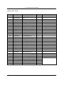
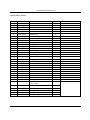
Model:SSH-P126DC
No. Part No. Part Name Q’ty Remark
1 1080030008 Installation plate 1
2 1080320806AC Base 1
3 1070020026AA indoor fan 1
4 1070100010 Bearing Mount 1
5 211205800 Evaporator 1
6 1070321572AC Water Drainage Assembly 1
7 1070321035 Vertical Vane Assembly 2
8 1070321678AE Face frame 1
9 1070321022AC Screw cover 2
10 1070320109 Air filter 2
11 1070252211 Display PCB box 1
12 1090321196 Display PCB 1
13 210706141 Panel 1
14 1170120045 Power supply cord 1
15 1070321034AE Vane 1
16 1070110011 Drainage hose 1
17 1070040004 Cable clamp 1
18 1170200042 Terminal 1
19 1070250109 Terminal fixing board 1
20 210900001AF main PCB 1
21 1070320113 Electrical box 1
22 1170020011 Vane motor 1
23 1073010501 Sensor holder 1
24 1170030067 Indoor motor 1
25 1070320111 Indoor motor cover 1
26 1170240001 Transformer 1
27 1170230001 indoor sensor assembly 1
28 1080320818AB In And Out Pipe Fixer 1
29 1090090001AL Remote controller 1
30 1070060003 Remote controller supporter 1
31 1190060828BKU Indoor cartoon 1
32 211310246 Left foaming 1
33 211310247 Right foaming 1
Air Conditioner Service Manual
Not shown in explosion view
14

No. Part No. Part Name Q’ty Remark
1 1080030021 Installation Plate 1
2 1070350872AD Base 1
3 1070020024AA Cross Fan 1
4 1070100010 Bearing Mount 1
5 211205865 Evaporator 1
6 1070450385AR Water Drainage Assembly 1
7 1070350141 Vertical Vane Assembly 1
8 1070450900AG Face Frame 1
9 1070350135AF Screw Cover 3
10 1070450397 Air Filter 1
11 1070252211 Display PCB Box 1
12 1090321196 Display PCB 1
13 210706142 Front Panel 1
14 1170120045 Power Supply Cord 1
15 1070450387AP Vane 1
16 1070110011 Drainage Hose 1
17 1070040004 Cable Clamp 1
18 1170200042 Terminal 1
19 210800637 Terminal fixing board 1
18 210900001AM Main PCB 1
19 1070451080 Electrical Box 1
20 1170020041 Vane Motor 2
21 1073030201 Sensor Holder 1
22 1170030065 Indoor Motor 1
23 1070350152 Indoor Motor Cover 1
24 1170240001 Transformer 1
25 1170230001 Indoor Sensor Assembly 1
26 1070350245AD In And Out Pipe Fixer 1
27 1090090001AL Remote Controller 1
28 1070060003 Remote Controller Supporter 1
29 1190470001BJL Indoor Carton 1
30 1190060803 Left Foaming 1
31 1190060804 Right Foaming 1
32 211310757 Middle Pasteboard Supporter 1
Air Conditioner Service Manual
Indoor Unit- SSH-P186DC
Not shown in Explosion view
15

Air Conditioner Service Manual
16
EXPLOSION VIEW
Mode: SRH-P076DC, SRH-P096DC, SRH-P126DC
OUTDOOR UNIT:
10 11 12
8
9
765
17
13 14 16
15
19
18
20
21
23
22
24
4321

Air Conditioner Service Manual
17
EXPLOSION VIEW
Mode: SRH-P186DC
OUTDOOR UNIT:
28
27
1
26
25
2
3
4
24
22
23
21
20
18
19
15 16
14
13
17
5
6
7
9
8
12
11
10

OUTDOOR UNIT
Model:SRH-P076DC
No. Part No. Part Name Q’ty Remark
1 1071990039 Grille 1
2 1080320105 Top cover 1
3 211202308A Condenser 1
4 1080050004 Outdoor motor supporter 1
5 1170040058 Outdoor motor 1
6 1070030050AA Propeller fan 1
7 1080050001 Left grille supporter 2
8 1080320113 Front plate 2
9 1080320112 Fan guard 1
10 211206855 Compressor and accessories 1
11 1120110016 4-way valve 1
12 211206864 4-way valve assembly 1
13 210800466 Base 1
14 1080050002 Right plate 1
15 1120120021 Two-way valve 1
16 1080050003 Valve supporter 1
17 1120130083 Three-way valve 1
18 1070350971 Electrical box cover 1
19 1070040008 Cable clamp 1
20 1170200061 Terminal 1
21 210900958 Outdoor PCB assembly 1
22 1160100002 Inductor 1
23 211206873 Capillary assembly 1
24 1081990328 Partition plate 1
25 1170230007A Pipe Temp. sensor and outdoor
Temp. sensor 1
26 1170230006A Discharge Temp. sensor 1
27 211311435 Base carton 1
28 211311098FM Cabinet carton 1
29 211311099 Base foaming 1
30 211311100 Cover foaming 1
Air Conditioner Service Manual
Not shown in explosion view
18

OUTDOOR UNIT
Model:SRH-P096DC
No. Part No. Part Name Q’ty Remark
1 1071990039 Grille 1
2 1080320105 Top cover 1
3 211202308A Condenser 1
4 1080050004 Outdoor motor supporter 1
5 1170040058 Outdoor motor 1
6 1070030050AA Propeller fan 1
7 1080050001 Left grille supporter 2
8 1080320113 Front plate 2
9 1080320112 Fan guard 1
10 211206855 Compressor and accessories 1
11 1120110016 4-way valve 1
12 211206864 4-way valve assembly 1
13 210800466 Base 1
14 1080050002 Right plate 1
15 1120120021 Two-way valve 1
16 1080050003 Valve supporter 1
17 1120130083 Three-way valve 1
18 1070350971 Electrical box cover 1
19 1070040008 Cable clamp 1
20 1170200061 Terminal 1
21 210900958 Outdoor PCB assembly 1
22 1160100002 Inductor 1
23 211206873 Capillary assembly 1
24 1081990328 Partition plate 1
25 1170230007A Pipe Temp. sensor and outdoor
Temp. sensor 1
26 1170230006A Discharge Temp. sensor 1
27 211311435 Base carton 1
28 211311098FN Cabinet carton 1
29 211311099 Base foaming 1
30 211311100 Cover foaming 1
Air Conditioner Service Manual
Not shown in explosion view
19

OUTDOOR UNIT
Model:SRH-P126DC
No. Part No. Part Name Q’ty Remark
1 1071990039 Grille 1
2 1080320105 Top cover 1
3 211230380 Condenser 1
4 1080050004 Outdoor motor supporter 1
5 1170040058 Outdoor motor 1
6 1070030050AA Propeller fan 1
7 1080050001 Left grille supporter 2
8 1080320113 Front plate 2
9 1080320112 Fan guard 1
10 211206855 Compressor and accessories 1
11 1120110016 4-way valve 1
12 211206864 4-way valve assembly 1
13 210800466 Base 1
14 1080050002 Right plate 1
15 1120120021 Two-way valve 1
16 1080050003 Valve supporter 1
17 1120130083 Three-way valve 1
18 1070350971 Electrical box cover 1
19 1070040008 Cable clamp 1
20 1170200061 Terminal 1
21 210900990 Outdoor PCB assembly 1
22 1160100002 Inductor 1
23 211204787 Capillary assembly 1
24 1081990328 Partition plate 1
25 1170230007A Pipe Temp. sensor and outdoor
Temp. sensor 1
26 1170230006A Discharge Temp. sensor 1
27 211311435 Base carton 1
28 211311098FP Cabinet carton 1
29 211311099 Base foaming 1
30 211311100 Cover foaming 1
Air Conditioner Service Manual
Not shown in explosion view
20
Page is loading ...
-
 1
1
-
 2
2
-
 3
3
-
 4
4
-
 5
5
-
 6
6
-
 7
7
-
 8
8
-
 9
9
-
 10
10
-
 11
11
-
 12
12
-
 13
13
-
 14
14
-
 15
15
-
 16
16
-
 17
17
-
 18
18
-
 19
19
-
 20
20
-
 21
21


Shivaki SSH-P076DC User manual
- Category
- Split-system air conditioners
- Type
- User manual
- This manual is also suitable for
Ask a question and I''ll find the answer in the document
Finding information in a document is now easier with AI
Other documents
-
Daewoo DSC-1285FL User manual
-
Hyundai HSH-L123NDC User manual
-
Klimaire KIWQ18H2-3T / KOIQ18H2-3 User manual
-
Soleus Air KFTHP-24 User manual
-
Ayre T50-M11 User manual
-
 BONAIRE Wall Splits Owner's manual
-
BOMANN CL 6045 QC CB Operating instructions
-
 Elitex TAC-12CHSA series User manual
-
 Dekker DSH 95 R/C User manual
-


