Page is loading ...

www.ayre.com.au
T-series Split System Air Conditioner
SERVICE MANUAL
• T27-M11 2.7kWSplitSystem
• T33-M11 3.2kWSplitSystem
• T50-M11 5.0kWSplitSystem
• T70-M11 7.0kWSplitSystem

Contents
1. Important notice ...............................................................2
2. Technical specications ..................................................3
3. Operation details ...............................................................4
4. Wiring diagrams ..............................................................12
5. Explosion views – indoor unit ....................................14
6. Explosion views – outdoor unit .................................18
Service Manual • T-series Split System Air Conditioner

Important notice
This service manual is intended for use by individuals possessing adequate
backgrounds of electrical, electronic and mechanical experience. Any attempt
to repair the appliance may result in personal injury and property damage.
The manufacturer or seller cannot be responsible for the interpretation of this
information, nor can it assume any liability in connection with its use.
The information, specifications and parameter are subject to change due to
technical modification or improvement without any prior notice. The accurate
specifications are presented on the nameplate label.
How to order spare parts
To have your order filled promptly and correctly, please furnish the following
information:
1. Model number with indoor or outdoor
2. Number in the explosion view
3. Part name
4. The quantity you require
2
Service Manual • T-series Split System Air Conditioner

T27-M11 T33-M11 T50-M11 T70-M11
Model No.
Technical specications
Control type
0007000,5002,3056,2Wyticapac gnilooc detaR
0007000,5002,3056,2Wyticapac gnitaeh detaR
352.3303.3776.3466.3W/WTested AEER for cooling
0.21.25.25.2gnilooc rof rats ygrenE
Tested ACOP for heating W/W 3.944 3.736 3.269 3.334
0.20.205.20.3gnitaeh rof rats ygrenE
8.12.18.08.0h/sretiLlavomer erutsioM
25842424)A(BdhgiH
05640483)A(Bd.deM
64348363)A(BdwoL
16068555)A(Bdlevel rewop dnuos roodtuO
Electrical Data
Power supply
VegnaR egatloV
5.90.79.34.3AgnilooC
2.98.68.31.3AgnitaeH
0022065,1098067WgnilooC
0012005,1068007WgnitaeH
618.011.69.4AgnilooC
714.211.63.4AgnitaeH
Cooling W 1,080 1,150 2,050 2900
Heating W 1,000 1,150 2,200 3100
Refrigerating System
0522004100110801marGA014RtnaregirfeR
Fan System
Indoor air circulation/Hi Cooling m3/h 750/600 700/700 1100/1100 1200
wolF ssorCwolF ssorCwolF ssorCwolF ssorCepyt naf roodnI
Cooling rpm 1270/1170/1000 1270/1170/1050 1330/1230/1150 1300/1200/1050
Heating rpm 1050/950/850 1250/1150/1000 1330/1230/1150 1300/1200/1050
Fan rpm 1000 1050 1150 1050
Sleep rpm 1000 1050 1150 1050
05533281Wtuptuo rotom naf roodnI
naf relleporPnaf relleporPnaf relleporPnaf relleporPepyt naf roodtuO
068068058009mprdeeps naf roodtuO
67555403Wtuptuo rotom naf roodtuO
Connections
''8/5''2/1''2/1''8/3sehcnIsaG
''8/3''4/1''4/1''4/1sehcnIdiuqiL
Others
Net dimension mm 898*280*200 898*280*200 1033*313*202 1240*325*250
(W x H x D) mm 760*552*256 820*605*300 902*650*307 900*805*360
61411111gk
96852492gk
Packing dimensions mm 995*365*298 995*365*298 1103*400*300 1317*422*338
(W x H x D) mm 863*605*376 965*650*438 1027*705*433 1031*835*447
52714141gk
27166413gk
198~265
Net weight
Gross weight
Connecting Pipe
Max Current
Max Power input
Rated current
Rated input
Indoor fan speed H/M/L
Remote
220-240V~50Hz
Indoor noise level at cooling
Indoor
Outdoor
Indoor
Outdoor
Indoor
Outdoor
Indoor
Outdoor
3
Service Manual • T-series Split System Air Conditioner

4
Note: Each mode and relevant function will be further specified in following pages.
SLEEP FAN
TIMER SWING
ON/OFF
MODE
MID
SWING
AUTO
DRY
FAN
HEAT
COOL
FEEL
SLEEP
TIMER ON
HIGH
LOW
TMIER OFF
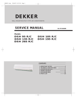
The remote controller transmits signals to the system.
Remote controller
1
2
4
3
5
6
7
8
8
4
MODE button
FAN SPEED control button
UP button (TOO COOL button)
DOWN button (TOO WARM button)
ON/OFF button
SLEEP button
VANE control button
TIMER button
Used to select the type of operation mode: Feel,
Cooling, Dry, Fan and Heating(Only for Heat Pump).
Used to select the indoor fan motor speed:
Auto, High, Mid and Low.
Used to increase the set room temperature
and time.
Used to decrease the set room temperature
and time.
Used to set or cancel sleep mode operation.
Used to start and stop operation
when pressed.
Used to adjust airflow direction.
Used to select TIMER operation.
Remote controller
6
2
5
3
7
1
Operation Details
Remote Control
The remote controller is not presetted as Cooling Only Air Conditioner or Heat Pump by manufacturer.
Each time after the remote controller replace batteries or is energized, the arrowhead will flashes on the front of
Heat or Cool on LCD of the remote controller.
User can preset the remote controller type depending on the air conditioner type you have purchased as
follows:
Press any button when the arrowhead flashes on the front of Cool , Cooling Only is set.
Press any button when the arrowhead flashes on the front of Heat , Heat Pump is set.
If you don t press any button within 10 seconds, the remote controller is preset as Heat Pump automatically.
Note :
If the air conditioner you purchased is a Cooling Only one, but you preset the remote controller as Heat Pump, it
doesn t bring any matter. But if the air conditioner you purchased is a Heat Pump one, and you preset the
remote controller as Cooling Only, then you CAN NOT preset the Heating operation with the remote controller.
Service Manual • T-series Split System Air Conditioner

5
Electronic controller:
1.Automatic mode
1) Initial RT determines the working mode and ST,the mode is determined effective only
once unless A/C shut-down then re-started. If from other modes switches to autoamatic
mode (including mode conversion after shutdown), it should be that the compress stop
more than 3 min then temperature judgement and automatic mode are conducted (it can
conduct immediately from fan mode switched to automatic, the indoor fan stops, three
minutes later the response is made and start up). Within 3 min, the output as: Showing
the room temperature, indoor fans starts (or anti-cold airflow), the outdoor fan stops;
2) With memory controller, once being turned off or in case of an accidently power cut, the
A/C is able to retain and restore the original mode when being turned on or the power
supply is resumed, if the auto restart function activated. power-down after power-on; while
if the auto restart fundction isn’t activated, the A/C enters standby state.
Heat pump
Mode Initial RT Initial ST
Cooling RT≥26℃ 23℃
Dehumifying 26℃>RT≥20℃ 18℃
Heating RT<20℃ 23℃
Cooling-only
Mode Initial RT Initial ST
Cooling RT≥26℃ 23℃
Dehumifying 26℃>RT≥20℃ 18℃
Ventilating RT<20℃ -
Under automatic mode (including from automatic converted into dehumidifying Dry mode),
when the temperature up and down signals from the remote controller is received, the
setting temperature ST adjusts correspondingly to the current room temperature plus or
minus 1℃, the automatic regulating temperature range is ± 2℃.
2.Cooling mode
1) The control of the compressor
a. When RT-ST≥1℃,the compressor is running.
b. When RT-ST<-1℃,the compressor is off.
c. When -1℃≤RT-ST<1℃, the compressor keeps its original state.
2) Outdoor fan motor and the compressor run simultaneously (except for defrosting).
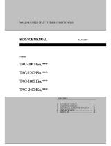
3) The control of indoor fan motor:
a. Indoor fan motor can operate by automatic, low, middle, and high airflow speed
circularly.
b. Indoor fan motor’s the automatic airflow speed control Indoor fan motor can operate by
automatic,as shown in Figure 1:
Hi
Mid
Lo
RT-ST 1℃ 2℃ 4℃
Figure 1 Cooling automatic airflow
Service Manual • T-series Split System Air Conditioner

6
When the temperature changes lead to changes in airflow speed, the switch can only be
made orderly, and every grade of air flow speed runs 1 minute at least.
3, Dry mode
running into this mode, the Air cond. firstly operates for 3 minutes according to cooling
mode (set temperature is 16℃ or 18℃) , and then takes the detected backflow air
temperature minus 2℃ as a new set temperature (the minimum value of 16℃) and runs
according to cooling mode, indoor fan operates at low-speed, at this moment the setting
operation of Fan speed is invalid but Swing is adjustable.
4. Heating mode
On the Heating mode, the room temperature is repaired. After repaired, the room
temperature display on the LED CRT=RT-3℃.
1) The control of the compressor
a. When ST-CRT≥1℃,the compressor is running.
b. When ST-CRT<-1℃,the compressor is off.
c. When -1℃≤ST-CRT<1℃, the compressor keeps its original state
2) Outdoor fan motor and the compressor run simultaneously (except for defrosting)
3) The control of indoor fan motor:
a. Indoor fan motor can operate by automatic, low, middle, and high airflow speed
circularly.
b. indoor fan motor’s the automatic airflow speed control Indoor fan motor can operate by
automatic,as shown in Figure 2:
Hi
Mid
Lo
ST-CRT 1℃ 2℃ 4℃
Figure 2 Heating automatic airflow
When the temperature changes lead to changes in airflow speed, the switch can only be
made orderly, and every grade of air flow speed runs 1 minute at least.
4) Vane motor control: run as set state.
5) 4-way valve control:
a. Under heating mode, the four-way valve maintains well-connected status (including the
compressor stops on set condition, but except for the defrosting process)
b. When the mode switches into the heating mode or start-up, four-way valves will open 5
Seconds before the compressor starts; while the mode exits from the heating mode or
turn off, the four-way valve will close 2min after after the shut-down the compressor.
6) Defrosting function:
During defrosting, once mode switch, temperature setting signals received, and the
buzzer and display make response immediately, but the other operations won’t
implemented until defrosting finished;
During defrosting, the signals of on-off, timing, sleep, airflow speed ans swing will be
responded, but the airflow speed and swing should be in accordance with anti-cold air
rules.
Service Manual • T-series Split System Air Conditioner

7
Except the above signal processing during defrosting, no other signals will be dealt with,
but only a loud buzz.
During defrosting, electrical heating stops compulsively.
Defrosting enter and exit pragram:
Option 1:with jumper JC
The condition of enter defrosting: run into defrosting once any of condition 1, 2, and 3 met.
Condition 1:As shown in figure 3
Defination:
The followings are all required to meet:
a. IPT1 settles for IPT1=IPTmax-△IPT(8℃)
b. t5≥50min(running time t5≥50min(the compressor runs cumulatively),t5 is removable,
and could be less than t1)
c. IPT<40℃,and lasts 2min。
Running into defrosting on condition 1, the first running time of set defrosting is F (8min);
after running a defrosting cycle, the defrosting time should be determined and adjusted.
Figure 3
Condition 2: When running time is more than or equal to 120 min (compressor is running
accumulatively), the indoor temperature is less than 35 ° C for 2 min sustained. Running
into defrosting under condition 2, defrosting time set is 8 min.
Condition 3: after the compressor is operating for 20min continuously, the indoor
temperature is less than 23 ° C which is anti-cold wind temperature when the fan stops
running(including temperature droping when compressor operating, not including the
compressor’s starting course), and the machine runs into defrosting according to any one
condiciton as below) Running into defrosting under condition 3, defrosting time set is 10
min.
a) Running into the first defrosting in 20 min after start-up.
b) The interval from last defrosting equivalent to or more than 50 min (stopping the
compressor or the machine in standby is allowed in the meantime).
Option 2: No Jumper JC, and no OPT outdoor sensor
Service Manual • T-series Split System Air Conditioner

8
when the compressor runs for 45 min, if the indoor coil temperature is less than 40 ° C for
2 min, the machine runs into defrosting, and lasts for 3min, otherwise when the
compressor runs for 120 min, the machine runs into defrosting automatically and last for
10 min.
Option 3: No jumper JC, but with OPT outdoor sensor
When heating, when the temperature of outdoor unit under heat-exchange is lower than E
° C (-4 ° C), and the compressor runs for 45 min, then the machine runs into defrosting
and last for 10 min.
Option 4. When heating, when the outdoor fan motor stopped but the compressor not
stopped accumulative total 30min, then the machine runs into defrosting and last for 8 min.
if the accumulative total less than 30min, but accord with one of the condition option 1-3
them the machine runs into defrosting at the option 1-3 and the accumulative tota time
restarts from 0.
Conditions for quitting defrostng
(1) The quitting conditions for option 1 and option 2, the machine quits from defrosting if
any one below condition met.
a. Defrosring time is over.
b.When it runs in defrosting for three minutes, the IPT indoor coil temperature rises 15 ° C
or above from the bottom point.
(2) The quitting conditions for option 3.
When OPT ≥ 20 ° C or defrosting for more than 10 min, then quit from defrosting.
(3) Defrosting process shown in Figure 4
Figure 4 Defrosting process
7) Auxiliary Electric heating function
(1)The default condition is automatic on/off the electric heating function.
(2) The conditions of auxiliary electric heating(all the following conditions must be met)
a. the compressor runs for more than 3min;
b. indoor fan runs normally;
c. not in defrosting state;
d. auxiliary electric heating is turned off for more than 30s。
e. ST-RT≥3°C;
f. RT﹤22°C;
Service Manual • T-series Split System Air Conditioner

9
g. IPT≤43°C;
(3) The conditions of stopping auxiliary electric heating(any one of the following conditions
met, the state stops)
a. the compressor stops
b. RT≥24°C;
c. IPT≥48°C
d. indoor fan stops。
e. running into sleeping function
5. Fan mode
1) Indoor fan motor control:
indoor fan motor is running at setting speed (the speed is same as that of heating).
2) Vane motor control: running according to the setting.
3) The outdoor unit is not working under fan mode.
6. Sleeping mode
1) Under sleep mode, the indoor fan motor is running at a low-airflow speed,except that
the power light and sleep light are on, timer light is on/off according to the setting state,
running light is off. LED is off after displaying 5min.
2) Temperature control:
(1) From cool mode to sleep mode, one hour later, the operates Temp.=ST+1,another
one hour later, the operates Temp.=ST+2,after then unchanged.
(2) From heating mode to sleep mode, one hour later, the operates Temp.= ST-1,
another one hour later, the operates Temp.=ST-2,after then unchanged.
3) the machine will automatically shut up after running 8 hours under sleep mode.
Timer on start-up and sleep mode are implemented at the same time, and the sleep mode
can not be functioned.
7. Timing fuction
The timing scale is between 10min to 24h, when the time fixed is less than “10” hours, the
displayed time is shown by 0.5 hour as the unit, when the time fixed is more than or equal
to “10” hours, the displayed time is shown by 1 hour as the unit.
8. Emergency switch(ON/OFF)
1) When stand-by, to operate by pressing the emergency switch as follows:
To Press the emergency switch in three seconds, the buzzer rings once, and to release,
the machine runs into cooling mode; if to holding on, the buzzer rings twince, then the
machine runs into heating mode, while when the machine is on, to press the emergency
Switch, the buzzer rings once and then the machine shut down.
2) The machine is running mandatorily as the selected mode within 30min after
emergency operation, indoor fan motor is running in high-speed, and vane board is
swinging. The machine runs into automatic mode 30min later, the selected mode
unchanged, the set temperature is 23° C ,the rotate speed of indoor fan motor is
automatic, and vane board is swinging too.
3) To press the emergency button when the machine operating, then the machine runs
into stand-by state.
4) Under emergency operation,the Compressor’s time-lapse protection, anti-frosting
Service Manual • T-series Split System Air Conditioner

10
protection in cooling, Overheating protection in heating and sensor fault protection and
defrost operate are effective.
5) Under emergency operation, once effective signal from remote controller is received,
then the machine exits form the emergency mode, and operate according to the setting
from remote controller.
9. Auto-restart function
1) The PCB retains the setting parameters in case of power off. When the power supply is
resumed, the machine, which has been started up the power-off memory function, is able
to restore into the original running state automatically.
2) To press the emergency button and power on, and hold on 10 seconds, exit from the
power-off memory function, buzzer rings four tomes.(default: no this function)
10. Protection/ Troubleshooting functions
1) Compressor’s protection function:
a.The PCB which has Power-off memory function, once this function is started up,the
compressor goes along 3min delay protection when power on. If the PCB hasn’t been
started up this function, even when the PCB is power-on, the compressor doesn’t process
3 min delay function.
b.Compressor’s 3 min interval protection: the compressor can’t start-up until 3 min
later(except for defrosting process).
c.After the compressor started, the compressor’s state isn’t subject to the changes on
ST,RT in 3min.
2) Anti-frosting protection of indoor evaporator:
If IPT ≤ 0 ℃ detected in consecutive 5 min, compressor and outdoor motor stoped,
indoor fan motor runs at high-speed forcibly; IPT ≥ 5 ℃ detected 3min later, then outdoor
fan is activated. And the compressor, indoor fan motor restores the original state.
3) Overheating protection:
IPT ≥ 55℃, the outdoor fan stops, IPT ≥ 65℃, the compressor stops, indoor fan motor
runs at high-speed forcibly. When IPT ≤ 48℃, outdoor fan motor and the compressor
open, indoor fan motor restores the original state.
4) Anti-cold wind control in heating:
a. When runing into the heating mode, once the compressor fails to comply with the
start-up conditions, the wind speed is regulated according to the coil temperature in 2
min(including stopping the indoor fan motor), 2 min later the indoor fan motor stops.If the
compressor starts up within 2 min, then operating by Figure 6.
Under heating process, to close the compressor (including the downtime protection ), the
wind speed is regulated according to the coil temperature in 1min(including stopping the
indoor fan), 1min later the fan is stoped forcibly.
b. When the indoor fan motor running at a low-speed wind and in anti-cold wind operation,
once electric heating opens,the vane immediately withdraws from the anti-cold windy
location and turn back to normal vane angle. When electric heating closes, indoor fan
motor go on to run at low-speed wind, accordingly, the vane turns to anti-cold windy
location.
Service Manual • T-series Split System Air Conditioner

11
Figure 5 Anti-cold Wind
2) The following table shows the fault protections. When failures happens, the PCB
alarms and buzzer rings three times. Failure code appears, and the PCB operates
protection procedures.
Failure code: For the machine has LED, the code displays on LED, for no LED machine,
the code reflects by the running light.
Failure Running Light Flash LED Display
RT Sensor Failure Once / Period E1
IPT Sensor Failure Twice / Period E2
Indoor Fan Motor Failure 6 times / Period E6
When there is LED displaying failure code, the code is displayed statically, if there are
several failure codes should be reported at the same time, then failure codes appears one
by one every eight seconds correspondingly.
a. Sensor’s failure protection: when the sensor’s temperature is out of the range -50 ≤ T ≤
110 ℃, then sensor failue is determined. Once RT, IPT sensor failures appear, the
compressor stops and indoor and outdoor fan motors shut off. Remote controller deesn’t
response to any signal except for shutdown. During failure the machine can run in fan
mode. After the failure is settled, the PCB restores to standby status.
b. Failure protection of Indoor PG fan motor:If there is no feedback signal of rotate speed
within 5, the indoor fan motor stops,at the same time, the compressor, outdoor fan moto,
four-way valve and auxiliary electric heater etc cut downn. 10 seconds later, the indoor fan
motor restarts, once there is no feedback signal of rotate speed within 5 seconds either,
then the machine stops and goes into indoor fan motor failure protection, buzzer rings
three times, and running light flashes at 6 times per 8 seceonds. When the failure is
confirmed, once there is feedback signal,the failue is relieved automatic.
Service Manual • T-series Split System Air Conditioner

12
WIRING DIAGRAM
MODEL: T27-M11, T33-M11, T50-M11
INDOOR UNIT:
OUTDOOR UNIT
Service Manual • T-series Split System Air Conditioner

13
WIRING DIAGRAM
MODEL: T70-M11
INDOOR UNIT:
OUTDOOR UNIT
Compressor
White(Black)
CM
CR(M)
SBlue
Red
Compressor
Capacitor
Fan
Yellow
YLW/GRN
Optional Part
Fan Motor
FM
Protector
White
Brown
Contactor
Power Supply
Outdoor Unit
Indoor Unit
Red
Blue
Blue
Blue
Yellow
Capacitor
YLW/GRN
YLW/GRN
White
Red
Blue
Blue
Blue
Brown
Blue
Red
White
Vane
1
2
3
N
L
O.P.T
L
N
L
N
3
2
1
Service Manual • T-series Split System Air Conditioner

14
EXPLOSION VIEW
INDOOR UNIT:
MODEL: T27-M11, T33-M11, T50-M11
15
6
14
11
13
12
8
10
9
7
1
5
4
3
2
19
18
17
16
23
24
21
20
22
26
25
27
Service Manual • T-series Split System Air Conditioner

No. Part No. Part Name Q’ty Remark
1 Installation Plate 1
2 Base 1
3 Cross Fan 1
4 Bearing Mount 1
5 Evaporator 1
6 Water Drainage Assembly 1
7 Vertical Vane Assembly 2
8 Face Frame 1
9 Screw Cover 2
10 Air Filter 2
11 Front Panel 1
12 Power Supply Cord 1
13 Vane 1
14 Drainage Hose 1
15 Display PCB Cover 1
16 Display PCB(Digital) 1
17 Display PCB Box 1
18 Cable Clamp 1
19 Main PCB(Digital) 1
20 Electrical Box 1
21 Vane Motor 1
22 Sensor Holder 1
23 Indoor Motor 1
24 Indoor Motor Cover 1
25 Transformer 1
26 Indoor Sensor Assembly 1
27 In And Out Pipe Fixer 1
28 Remote Controller 1
29 Remote Controller Supporter 1
30 Indoor Carton 1
31 Left Foaming 1
32 Right Foaming 1
15
Not shown in Explosion
view
Indoor Unit
Part List - T27-M11, T33-M11, T50-M11
Service Manual • T-series Split System Air Conditioner

16
EXPLOSION VIEW
INDOOR UNIT:
MODEL: T70-M11
8
13 14
11
12
10 9
15
4
6
7
5
3
1
2
24
20
21
16
17
18
19
23
22
25
26
Service Manual • T-series Split System Air Conditioner

Part List
No. Part No. Part Name Q’ty Remark
1 Installation Plate 1
2 Base 1
3 Cross Fan 1
4 Bearing Mount 1
5 Evaporator 1
6 Water Drainage Assembly 1
Vertical Vane Assembly A 1
Vertical Vane Assembly B 1
8 Face Frame 1
9 Screw Cover 3
Left Air Filter 1
Right Air Filter 1
11 Front Panel 1
12 Display PCB Cover 1
13 Display PCB (digital) 1
14 Vane A 1
15 Vane B 1
16 Drainage Hose 1
17 Cable Clamp 1
18 Vane Motor 2
19 Sensor Holder 1
20 Main PCB(digital) 1
21 Indoor Motor Cover 1
22 Indoor Motor 1
23 Electrical Box 1
24 Transformer 1
25 Indoor Sensor Assembly 1
28 Remote Controller 1
29 Remote Controller Supporter 1
30 Indoor Carton 1
31 Left Foaming 1
32 Right Foaming 1
33 Middle Pasteboard Supporter 1
34 Middle Foaming Supporter 1
Not shown in Explosion
view
Indoor Unit- T70-M11
7
10
17
Service Manual • T-series Split System Air Conditioner

18
EXPLOSION VIEW
Model: T27-M11, T33-M11, T50-M11
OUTDOOR UNIT:
10 11 12
8
9
765
17
13 14 16
15
19
18
20
21
23
22
24
432
25
26
27
1
Service Manual • T-series Split System Air Conditioner

Part List
No. Part No. Part Name Q’ty Remark
1 Grille 1 Optional
2 Top Cover 1
3 Condenser 1
4 Outdoor Motor Supporter 1
5 Outdoor Motor 1
6 Propeller Fan 1
7 Left Grille Supporter 1
8 Front Plate 1
9 Fan Guard 1
10 Compressor And It Accessories 1
11 4-way Valve 1
12 4-way Valve Assembly 1
13 Base 1
14 Right Plate 1
15 Two-way Valve 1
16 Valve Supporter 1
17 Three-way Valve 1
18 Electrical Box Cover 1
19 Cable Clamp(φ6) 1
20 Cable Clamp(φ8) 1
21 Terminal 1
22 Fan Motor Capacitor 1
23 Compressor Capacitor 1
24 Capacitor Strip 1
25 Electrical Parts Box 1
26 Capillary Assembly 1
27 Partition plate 1
28 Outdoor Sensor 1
29 Base Carton 1
30 Cabinet Carton 1
31 Base Foaming 1
32 Cover Forming 1
19
Outdoor Unit- T27-M11, T33-M11, T50-M11
Not shown in the Explosion view.
Service Manual • T-series Split System Air Conditioner
/