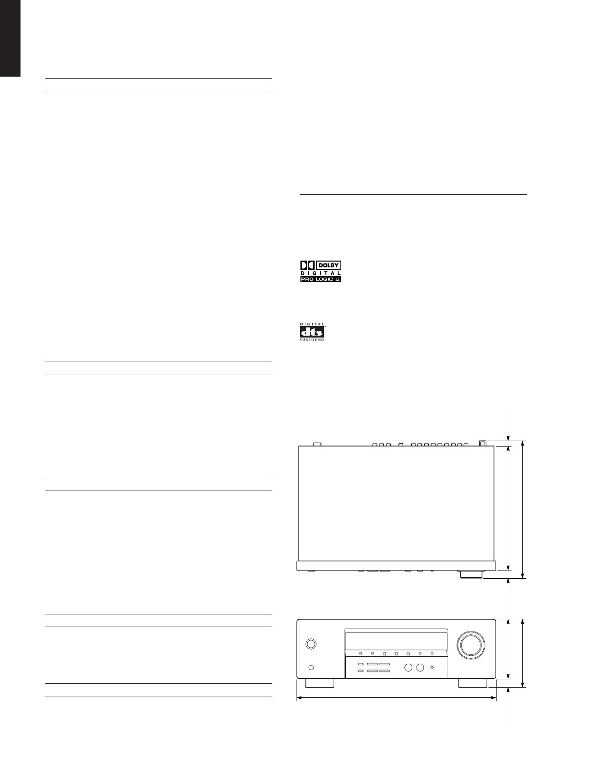
Yamaha HTR-5920 User manual

Category
AV receivers
Type
User manual

This manual is also suitable for

Yamaha HTR-5920 is a digital home theater system that combines a powerful AV receiver with a versatile speaker setup to deliver an immersive audio experience. With its 5.1-channel surround sound capabilities, you can enjoy movies, music, and games with crystal-clear audio and powerful bass. The system also features a variety of connectivity options, including HDMI, optical, and coaxial inputs, allowing you to easily connect your Blu-ray player, gaming console, or other devices.

Yamaha HTR-5920 is a digital home theater system that combines a powerful AV receiver with a versatile speaker setup to deliver an immersive audio experience. With its 5.1-channel surround sound capabilities, you can enjoy movies, music, and games with crystal-clear audio and powerful bass. The system also features a variety of connectivity options, including HDMI, optical, and coaxial inputs, allowing you to easily connect your Blu-ray player, gaming console, or other devices.

SERVICE MANUAL
101001
IMPORTANT NOTICE
This manual has been provided for the use of authorized YAMAHA Retailers and their service personnel.
It has been assumed that basic service procedures inherent to the industry, and more specifically YAMAHA Products, are already
known and understood by the users, and have therefore not been restated.
WARNING: Failure to follow appropriate service and safety procedures when servicing this product may result in personal
injury, destruction of expensive components, and failure of the product to perform as specified. For these reasons,
we advise all YAMAHA product owners that any service required should be performed by an authorized
YAMAHA Retailer or the appointed service representative.
IMPORTANT: The presentation or sale of this manual to any individual or firm does not constitute authorization, certification or
recognition of any applicable technical capabilities, or establish a principle-agent relationship of any form.
The data provided is believed to be accurate and applicable to the unit(s) indicated on the cover. The research, engineering, and
service departments of YAMAHA are continually striving to improve YAMAHA products. Modifications are, therefore, inevitable
and specifications are subject to change without notice or obligation to retrofit. Should any discrepancy appear to exist, please
contact the distributor's Service Division.
WARNING: Static discharges can destroy expensive components. Discharge any static electricity your body may have
accumulated by grounding yourself to the ground buss in the unit (heavy gauge black wires connect to this buss).
IMPORTANT: Turn the unit OFF during disassembly and part replacement. Recheck all work before you apply power to the unit.
CONTENTS
TO SERVICE PERSONNEL .......................................... 2
FRONT PANEL .............................................................. 2
REAR PANEL ................................................................ 3
REMOTE CONTROL PANEL ........................................ 3
SPECIFICATIONS...................................................... 4–6
INTERNAL VIEW ........................................................... 6
DISASSEMBLY PROCEDURES ............................... 7–9
MAINTENANCE FLOW CHART 10–17
DISPLAY DATA ..................................................... 18–19
IC DATA ................................................................. 20–22
PIN CONNECTION DIAGRAMS ............................ 23–24
BLOCK DIAGRAM ....................................................... 25
PRINTED CIRCUIT BOARDS................................ 26–30
SCHEMATIC DIAGRAMS ...................................... 31–34
REPLACEMENT PARTS LIST .............................. 35–37
REMOTE CONTROL.................................................... 38
DIGITAL HOME THEATER SYSTEM YHT-170
AV RECEIVER
HTR-5920
P.O.Box 1, Hamamatsu, Japan
2006 All rights reserved.
This manual is copyrighted by YAMAHA and may not be copied or
redistributed either in print or electronically without permission.
HTR-5920
YHT-170 consists of the HTR-5920 and the NS-P170.
This service manual is for the HTR-5920.
For the NS-P170 service manual, please refer to the following publication number:
NS-P170 101002
'06.03
HTR-5920
2
HTR-5920
WALL
OUTLET
EQUIPMENT
UNDER TEST
AC LEAKAGE
TESTER OR
EQUIVALENT
INSULATING
TABLE
TO SERVICE PERSONNEL
1. Critical Components Information
Components having special characteristics are marked s and
must be replaced with parts having specifications equal to those
originally installed.
2. Leakage Current Measurement (For 120V Models Only)
When service has been completed, it is imperative to verify
that all exposed conductive surfaces are properly insulated
from supply circuits.
Meter impedance should be equivalent to 1500 ohms shunted
by 0.15µF.
Leakage current must not exceed 0.5mA.
Be sure to test for leakage with the AC plug in both polarities.
WARNING: CHEMICAL CONTENT NOTICE!
The solder used in the production of this product contains LEAD. In addition, other electrical/electronic and/or plastic (where
applicable) components may also contain traces of chemicals found by the California Health and Welfare Agency (and
possibly other entities) to cause cancer and/or birth defects or other reproductive harm.
DO NOT PLACE SOLDER, ELECTRICAL/ELECTRONIC OR PLASTIC COMPONENTS IN YOUR MOUTH FOR ANY REA-
SON WHATSOEVER!
Avoid prolonged, unprotected contact between solder and your skin! When soldering, do not inhale solder fumes or expose
eyes to solder/flux vapor!
If you come in contact with solder or components located inside the enclosure of this product, wash your hands before
handling food.
FRONT PANEL
U, C models
HTR-5920
3
HTR-5920
REAR PANEL
U, C models
REMOTE CONTROL PANEL
HTR-5920
4
HTR-5920
151 (5-15/16")
130 (5-1/8") 270 (10-5/8")
21
(13/16")
21
(13/16")
12
(1/2")
303 (11-15/16")
435 (17-1/8")
mm (inch)Unit :
Audio Section
Minimum RMS Output Power Per Channel for FRONT,
CENTER and SURROUND
1 kHz, 0.1 % THD, 6 ohms ................................... 80 W
1 kHz, 10 % THD, 6 ohms .................................. 110 W
Frequency Response
CD, etc. to FRONT L/R ........... 10 Hz to 100 kHz, -3 dB
Total Harmonic Distortion
1 kHz, CD, etc. to FRONT L/R ............................. 0.1 %
Signal to Noise Ratio (IHF-A network)
CD, etc. to FRONT L/R, effect off ........................ 99 dB
Residual Noise (IHF-A network)
............................................................................ 150 µV
Channel Separation (1 kHz / 10 kHz)
CD, etc. (5.1 k-ohms terminated) to FRONT L/R
................................................... 60 dB/45 dB or more
Tone Control Characteristics (FRONT L/R)
BASS
Boost/cut ........................................... ±10 dB (100 Hz)
TREBLE
Boost/cut ........................................... ±10 dB (10 kHz)
Phones Output
.......................................................... 400 mV/470 ohms
Input Sensitivity / Input Impedance
CD, etc . .......................................... 200 mV/47 k-ohms
Output Level / Output Impedance
REC OUT ...................................... 200 mV/1.2 k-ohms
Video Section
Video Signal Type
..............................................................................NTSC
Component Signal Level
.............................................................. 1 Vp-p/75 ohms
Signal to Noise Ratio
............................................................. 50 dB or more
Frequency Response (Monitor out)
Composite ..................................5 Hz to 10 MHz, -3 dB
Component ................................. 5 Hz to 60 MHz, -3 dB
FM Section
Tuning Range
.......................................................... 87.5 to 107.9 MHz
50dB Quieting Sensitivity (IHF, 100% mod.)
Mono .................................................................... 30 dBf
Signal to Noise Ratio (IHF)
Mono/stereo .............................................. 73 dB/70 dB
Harmonic Distortion
(1 kHz)
Mono/stereo ............................................... 0.5 %/0.8 %
Antenna Input
......................................................75 ohms unbalanced
AM Section
Tuning Range
............................................................ 530 to 1,710 kHz
Antenna
................................................................. Loop antenna
General
Power Supply
U, C models ........................................ AC 120 V, 60 Hz
Power Consumption
U, C models ............................................ 220 W/240 VA
Standby Power Consumption
U, C models ............................................................. 1 W
Dimensions (W x H x D)
......
435 x 151 x 303 mm (17-1/8" x 5-15/16" x 11-15/16")
Weight
.................................................... 8.0 kg (17 lbs. 10 oz.)
Finish
Silver color ................................................. U, C models
Accessories
Remote control x 1, Batteries (Size "AA", R06, UM-3) x
2, AM loop antenna x 1, Indoor FM antenna x 1
* Specifications are subject to change without notice due
to product improvements.
U ........ U.S.A. model C .... Canada model
Manufactured under license from Dolby Laboratories.
“Dolby”, “Pro Logic”, and the double-D symbol are
trademarks of Dolby Laboratories.
“DTS”, and “DTS Digital Surround” are registered
trademarks of Digital Theater Systems, Inc.
SPECIFICATIONS
• DIMENSIONS
HTR-5920
5
HTR-5920
SET MENU TABLE
MAIN MENU SELECT MENU VALUE [INITIAL]
1
2
3
4
FRONT L
CENTER
FRONT R
SURROUND R
SURROUND L
SUBWOOFER
FRONT
CENTER
SURROUND
SUBWOOFER
FRONT
CENTER
SURROUND
-10 dB to +10 dB, [0 dB], 1 dB step
LRG, [SML], NONE
[YES], NONE
1 ft to 30 ft, [10 ft], 1 ft step
-2, -1, [0]
SPEAKER LEVEL
SPEAKER SET
SPEAKER DISTANCE
DIMMER
SURROUND MODE
MAIN MENU SELECT MENU VALUE [INITIAL]
PANORAMA
DIMENSION
CT WIDTH
ON, [OFF]
-3 to 3, [STD], 1 step
0 to 7, [3], 1 step
PLII MUSIC
RESETTING THE SYSTEM
Use this feature to reset all the parameters of this unit to the initial factory settings.
Note:
Be sure this unit is in standby mode.
This procedure completely resets all the parameters of this unit.
The initial factory settings are activated next time you turn on this unit.
1. With this unit in standby mode, hold down TONE CONTROL key on the front panel and press STANDBY/ON key.
"RESET > NO" appears in the front panel display.
Note: To cancel the initialization procedure without making any changes, press STANDBY/ON key.
2. Press TONE CONTROL key to select "RESET > YES".
3. Press STANDBY/ON key to confirm your selection and set this unit to the standby mode.
HTR-5920
6
HTR-5920
AMP (2) P.C.B.
AMP (3) P.C.B.
POWER TRANSFORMER
AMP (7) P.C.B.
AMP (1) P.C.B.
INPUT P.C.B.
AMP (4) P.C.B.
AMP (5) P.C.B.
AMP (6) P.C.B.
FRONT (3) P.C.B.
FRONT (2) P.C.B.
FRONT (1) P.C.B.
0BA
1254 63
7
8
9
1
2
3
4
5
6
7
8
9
0
A
B
Turn on the power while pressing these keys.
Keys of main unit
INTERNAL VIEW
FIRMWARE VERSION (Microprocessor information)
To display the firmware version, do the following procedure.
1. Press the "STANDBY/ON" key while simultaneously pressing those two keys of the main unit as indicated in the
figure below.
2.
* Numeric values in the figure example are for reference.
3. Press "STANDBY/ON" key.
060105-01
HTR-5920
7
HTR-5920
2
1
1
4
3
3
3
Ground lead
Ground lead
CN83
CN96
Front Panel Unit
CN11
Top Cover
DISASSEMBLY PROCEDURES
Fig. 1
(Remove parts in the order as numbered.)
Disconnect the power cable from the AC outlet.
1. Removal of Top Cover
a. Remove 6 screws (1) and 7 screws (2) (Fig. 1)
b. Slide the Top Cover rearward to remove it. (Fig. 1)
2. Removal of Front Panel Unit
a. Remove CN11, CN83, CN96. (Fig. 1)
b. Remove 5 screws (3) and 5 screws (4). (Fig. 1)
c. Release a hook on the right side of the Front Panel
Unit, then remove the Front Panel Unit forward. (Fig. 1)
HTR-5920
8
HTR-5920
5 67 7
8
CN12
TUNER
Rear PanelCord Stopper
Fig. 3
Fig. 4
3. Removal of Rear Panel and Tuner
a. Remove CN12. (Fig. 2)
b. Remove 2 screws (5). (Fig. 3)
c. Remove Tuner. (Fig. 2)
d. Remove 15 screws (6). (Fig. 3)
e. Remove 2 screws (7). (Fig. 3)
f. Remove 6 screws (8). (Fig. 4)
g. Remove Cord Stopper. (Fig. 2)
h. Remove Rear Panel. (Fig. 2)
Fig. 2
HTR-5920
9
HTR-5920
9
0
INPUT P.C.B.
AMP (4) P.C.B.
Note:
When assembling the AMP (4) P.C.B., be careful not to
bend the pin of the connectors (BN92 and BN94).
Note:
When assembling the AMP (4) P.C.B., be careful not to
bend the pin of the connectors (CN13 and CN14).
Heat Sink
AMP (1) P.C.B.
CN95
CN93 CN91 CN90
B
B
A
C
4. Removal of INPUT and AMP (4) P.C.B.s
a. Remove 1 screw (9) and 2 screws (0). (Fig. 5)
b. Remove INPUT and AMP (4) P.C.B.s. (Fig. 5)
Fig. 5
5. Removal of AMP (1) P.C.B.
a. Remove 2 screw (A) 5 screws (B) and 3 screw (C).
(Fig. 6)
b. Remove CN90, CN91, CN93 and CN95. (Fig. 6)
c. Remove AMP (1) P.C.B. with Heat Sink.
Fig. 6
HTR-5920
10
HTR-5920
MAINTENANCE FLOW CHART
NO
NO
NO
YES YES
YES
YES
YES
YES
YES
Power on
Is FL display
turns on?
Are all keys
on front panel
work well?
Is connection
of cable
correct?
Are voltages
of BN82 (pin 1
to 4) correct?
Check connection
of cable
NO
NO
NO
NO
Check power supply
of BN82
Check and replace
IC81
Check
power supply part
Check KEY IN part
(S851-854, S858-863,
S865-871)
Are waveforms
of IC81 (pin 34 to 67)
correct?
Check and replace
FL display
Are input ports
of IC81 (pin76 to 78)
work correct?
Check and replace IC81
Start
Is power voltage
of each board
correct?
A
FRONT P.C.B. 1/3
FRONT P.C.B.
HTR-5920
11
HTR-5920
NO
NO
NO
NO
NO
NO
NO
Is volume
work well?
Is output of
Phones
correct?
Are inputs of
IC81 (pin 71 and 72)
correct?
Check
power supply part
Check and replace
VR82
Check
power supply part
Check connection
of cable
Check circuit pattern
Check and replace IC81
Is implementation
of VR82
correct?
Is power voltage
of each board
correct?
A
B
Is power voltage
of each board
correct?
Are connections
of CN96 and BN73-2
correct?
Check and replace JK81
YES YES
YES
YES
YES
YES YES
FRONT P.C.B. 2/3
HTR-5920
12
HTR-5920
Is work
of remote control?
Is waveform
of RC81
correct?
Check and replace IC81
Is power voltage
of RC81 correct?
Is power voltage
of each board
correct?
FRONT P.C.B. is O.K.
NO
NO
NO
Check
power supply part
Check
power supply part
Check and replace
RC81
NO
B
YES YES
YES
YES
FRONT P.C.B. 3/3
HTR-5920
13
HTR-5920
Is Input
selector of IC21
correct?
Are
outputs of VCR,
MD/CD-R
correct?
Check connections for
BN14 and AMP board
Check connections for
CN11 and FRONT board
Check and replace IC21
Analog part is O.K.
Check and replace
IC21
NO
NO
NO
YES YES
YES
YES YES
Power on
NO
NO
Check and replace IC81
and JK12
Start
Are power
voltages of IC22 and
IC23 correct?
Are
waveforms of
IC21 (pin 67 to 69)
correct?
Are
waveforms of
IC21 (pin 76 to 79)
correct?
INPUT P.C.B. 1/3
(Analog part)
INPUT P.C.B.
HTR-5920
14
HTR-5920
Is recognition
of digital source
correct?
Are input
waveforms of IC32
(pin 57 and 59)
correct?
Are
waveforms
of IC32 (pin 14 to 20)
correct?
Check connections for
external device
Check power supply
part and crystal
oscillation part
Are
power voltage
and oscillation of
IC32 correct?
Are
waveforms
of IC31 (pin 39 to 41)
correct?
Are
waveforms
of IC32 (pin 39 to 50)
correct?
Are
waveforms of
IC31 (pin 6, 7 and 18)
correct?
NO NO
YES YES
YES
YES
YES
YES
Power on
NO
NO Check and replace
IC32
NO Check and replace
IC32
NO Check and replace
IC32
NO Check and replace
IC32
Check analog part
Start
YES
C
D
INPUT P.C.B. 2/3
(Digital part)
HTR-5920
15
HTR-5920
Is output
correct, when
analog input
Are
waveforms of
IC32 (pin 51 and 52)
correct?
Are
power voltage and
ground of IC32
correct?
Digital part is O.K.
Check power supply
part
NO
YES YES
YES
NO
NO Check and replace
IC32
C
D
INPUT P.C.B. 3/3
(Digital part)
HTR-5920
16
HTR-5920
Does protect
circuit work?
Is connection of
all cable correct?
Check voltages
CN94 pin 2 : low
CN96 pin 5 : 1.5V
Check Protect circuit
and power supply part
Check and replace
speaker relay (RY62-64)
Is
implementation
of speaker relay
correct?
Are power
voltages of IC91
to 93 correct?
Is input power
voltage (AC) of D901
correct?
Is output power
voltage (DC) of D901
correct?
Check connections of
cable
Check Front Board
Check Power
transformer
NO NO
YES YES
YES
YES
Power on
NO
NO
Check and replace
D901
NO
Check IC91 to 93
Start
YES
NO
E
AMP P.C.B. 1/2
AMP P.C.B.
HTR-5920
17
HTR-5920
AMP P.C.B. 2/2
NO
YES
Is output
audio correct?
Check connections of
speaker cable
AMP board is O.K.
E
HTR-5920
18
HTR-5920
DISPLAY DATA
1G 2G 3G 4G 5G 6G 7G 8G 9G
Dp
(11G)(2G-10G)
s1 s2 s1
s3 s4 s3
10G 11G
Note : 1) F+, - ..... Filament Pin 2) NP ..... No pin 3) NX ..... No extended pin 4) nG ..... Grid Pin 5) Pn ..... Anode Pin
Pin No.
Connection
Pin No.
1
F-
2
NX NX NX
3
NP
4
NP
5
1G 2G 3G 4G 5G 6G 7G 8G 9G
10G 11G
6 7 8 9 10 11 12 13 14 15 16 17 18
P21
19
P20
20
P19
21
P18
22
P17
23
P16
24
P15
25
P14
26
P13
27
P12
28
P11
29
P10
30
P9
31
P8
32
P7
33
P6
36
P3
37
P2
38
P1
39 40 41 42
F+NXNPNP
34
P5
35
P4
Connection
HNA-11SM66T
PIN CONNECTION
GRID ASSIGNMENT
PATTERN AREA
1b
a1 a2
d1 d2
b
m
c
fhk
rn
j
p
g
e
HTR-5920
19
HTR-5920
P1
1G 2G 3G 4G 5G 6G 7G 8G 9G 10G 11G
P2
P3
P4
P5
P6
P7
P8
P9
P10
P11
P12
P13
P14
P15
P16
P17
P18
f
a1
a2
h
j
k
b
m
g
e
r
p
n
c
d1
d2
f
a1
a2
h
j
k
b
m
g
e
r
p
n
c
d1
d2
f
a1
a2
h
j
k
b
m
g
e
r
p
n
c
d1
d2
f
a1
a2
h
j
k
b
m
g
e
r
p
n
c
d1
d2
f
a1
a2
h
j
k
b
m
g
e
r
p
n
c
d1
d2
f
a1
a2
h
j
k
b
m
g
e
r
p
n
c
d1
d2
f
a1
a2
h
j
k
b
m
g
e
r
p
n
c
d1
d2
f
a1
a2
h
j
k
b
m
g
e
r
p
n
c
d1
d2
Dp
f
a1
a2
h
j
k
b
ms3
g
e
s1
s2
s4
r
p
n
c
d1
d2
P19
P20
P21
ANODE CONNECTION
HTR-5920
20
HTR-5920
IC DATA
IC81: TMP87PS71AF (FRONT P.C.B.)
Microprocessor
P96 (S14)
P95 (S13)
P94 (S12)
P93 (S11)
P92 (S10)
P91 (S9)
P90 (S8)
P87 (S7)
P86 (S6)
P85 (S5)
P84 (S4)
P83 (S3)
P82 (S2)
P81 (S1)
P80 (S0)
P77 (G0)
P76 (G1)
P75 (G2)
P74 (G3)
(SIS) P97
123456789101112131415161718192021222324
55565758596061626364 54 53 52 51 50 49 48 47 46 45 44 43 42 41
40
39
38
37
36
35
34
33
32
31
30
29
28
27
26
25
65
66
67
68
69
70
71
72
73
74
75
76
77
78
79
80
VKK
(KEY0) P40
(KEY1) P41
(KEY2) P42
(KEY3) P43
(KEY4) P44
(KEY5) P45
(CIN5/KEY6) P46
(CIN4/KEY7) P47
(CIN3) P50
(CIN2) P51
(CIN1) P52
(CIN0) P53
P54
(PWM/PDO) P55
P73 (G4)
P72 (G5)
P71 (G6)
P70 (G7)
P67 (G8)
(INT0) P10
(INT1) P11
(INT2/TC1) P12
(DVO) P13
P14
(TC2) P15
P16
P17
TEST
(XTIN) P21
(XTIN) P22
RESET
XIN
XOUT
VSS
(INTS/STOP) P20
(INT3/TC3) P30
(TC4) P31
(SCK) P32
(SI) P33
(SO) P34
(HSCK) P35
P36
(HSO) P37
P66 (G9)
P65 (G10)
P64 (G11)
P63 (G12)
P62 (G13)
P61 (G14)
P60 (G15)
VDD
P07
P06
P05
P04
P03
P02
P01
P00
VDD P9
VFT drive circuit (automatic display) Key scan
control
Program counter
Register banks
Stack PointerP S W
Interrupt Controller
System Controller
Standby Controller
Timing Generator
High
frequ.
Low
frequ.
Clock
Generator
Time Base
Timer
16-bit
Timer/Counters
TC1 TC2 TC3 TC4 SIO HSO
8-bit
Timer/Counters
Serial
Interfaces
6-bit
Comparator
P4
P47
to
P40
P5
P55
to
P50
P3
P37
to
P30
P1
P17
to
P10
P0
P07
to
P00
P2
P22
to
P20
Inst.
Register
Inst.
Decoder
Watchdog
Timer
Flags
ALU RBS
Program Memory
(ROM)
Data Memory
(RAM)
I/O Ports
P97
to
P90
P8
Output Ports
P87
to
P80
P7
I/O Ports
P77
to
P70
P6
P67
to
P60
Power Supply
VFT Power
Supply
Reset I/O
Test Pin
Resonator
connecting
Pins
VSS
VKK
RESET
TEST
XIN
XOUT
I/O Ports
1 / 1

Yamaha HTR-5920 User manual

Category
AV receivers
Type
User manual
This manual is also suitable for

Yamaha HTR-5920 is a digital home theater system that combines a powerful AV receiver with a versatile speaker setup to deliver an immersive audio experience. With its 5.1-channel surround sound capabilities, you can enjoy movies, music, and games with crystal-clear audio and powerful bass. The system also features a variety of connectivity options, including HDMI, optical, and coaxial inputs, allowing you to easily connect your Blu-ray player, gaming console, or other devices.

Ask a question and I''ll find the answer in the document

Finding information in a document is now easier with AI

Ask the document