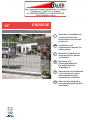
Bauer CROSS3E Installation and Maintenance Manual
- Category
- Gate Opener
- Type
- Installation and Maintenance Manual
Page is loading ...
Page is loading ...

CROSS3E - IP1780
3
RXTX
min
500
~100
~100
300÷600
RX RX
TX TX
1
CROSS3SF
2
22
60 W max
Type:
CENTRA A CL60
230 V~ E27/ES
INSTALLAZIONE LUXK3E - LUXK3E INSTALLATION
INSTALLAZIONE CROSS3SF - CROSS3SF INSTALLATION
73RP
24 V~
TRANSF
LUXK3E
CNO
Alimentazione
Power supply
230 V~ 50/60Hz
CROSS3E
Fig. 5
Fig. 4

CROSS3E - IP1780
4
INSTALLAZIONE BATK3 - BATK3 INSTALLATION
+
-
+
-
FUSE
-
+
+
-
FUSE
M
F10A
to control panel
nero/black
rosso/red
BATTERY
CONTROL
CIRCUIT
Fig. 6
Page is loading ...
Page is loading ...
Page is loading ...
Page is loading ...
Page is loading ...
Page is loading ...

CROSS3E - IP1780
11
GENERAL SAFETY PRECAUTIONS
This installation manual is intended for professionally
competent personnel only.
Installation, electrical connections and adjustments must be
performed in accordance with Good Working Methods and in
compliance with applicable regulations. Before installing the
product, carefully read the instructions. Bad installation could
be hazardous.
The packaging materials (plastic, polystyrene, etc.) should not
be discarded in the environment or left within reach of children,
as these are a potential source of hazard. Before installing the
product, make sure it is in perfect condition.
Do not install the product in an explosive environment and atmo-
sphere: gas or inammable fumes are a serious hazard risk.
Before installing the motors, make all structural changes relating
t o safety clearances and protection or segregation of all areas
where there is risk of being crushed, cut or dragged, and danger
areas in general.
Make sure the existing structure is up to standard in terms of
strength and stability.
The motor manufacturer is not responsible for failure to use
Good Working Methods in building the frames to be motorised
or for any deformation occurring during use.
The safety devices (photocells, safety edges, emergency stops,
etc.) must be installed taking into account: applicable laws and
directives, Good Working Methods, installation premises, system
operating logic and the forces developed by the motorised door
or gate.
The safety devices must protect any areas where the risk exists
of being crushed, cut or gragged, or where there are any other
risks generated by the motorised door or gate. Apply hazard
area notices required by applicable regulations.
Each installation must clearly show the identication details of
the motorised door or gate.
Before making power connections, make sure the plate
details correspond to those of the power mains.
Fit an omnipolar disconnection switch with a contact opening
gap of at least 3 mm. Make sure an adequate residual current
circuit breaker and overcurrent cutout are tted upstream of
the electrical system. When necessary, connect the motorised
door or gate to a reliable earth system made in accordance with
applicable safety regulations. During installation, maintenance
and repair, interrupt the power supply before opening the lid to
access the electrical parts.
To handle electronic parts, wear earthed antistatic con-
ductive bracelets.
The motor manufacturer declines all responsibility in the event
of component parts being tted that are not compatible with the
safe an correct operation.
For repairs or replacements of products only original spare parts
must be used.
The installer shall provide all information relating to automatic,
manual and emergency operation of the motorised door or gate,
and provide the user with operating instructions.
MACHINERY DIRECTIVE
Pursuant to Machine Directive (98/37/EC) the installer who mo-
torises a door or gate has the same obligations as a machine
manufacturer and shall:
- prepare technical documentation containing the documents
indicated on Schedule V of the Machine Directive;
(The technical documentation shall be kept and placed at the
disposal of competent national authorities for at least ten years
starting on the date of manufacture of the motorised door);
- draw up the EC declaration of conformity according to Sche-
dule II-A of the Machine Directive;
- afx the CE mark on the motorised door pursuant to para.
1.7.3 of Schedule I of the Machine Directive.
For more details, refer to the “Guidelines for producing technical
documentation” available on Internet at the following address:
www.ditec.it
APPLICATIONS
Service class: 3 (minimum 30 cycles a day for 10 years or 60
cycles a day for 5 years)
Use: FREQUENT (for multi-family entrances or small condomi-
niums with frequent car or pedestrian transit)
- The operating performance specications refer to the re-
commended weight (about 2/3 of maximum allowed weight).
Use with maximum allowed weight could reduce the above
performance specications.
- The service class, operating times and number of conse-
cutive cycles are merely approximate. These have been
statistically determined in average conditions of use and
are not certain for each single case. They refer to the pe-
riod when the product operates without the need for special
maintenance.
- Each automatic entrance features variable factors such as:
friction, balancing and environmental conditions that can
substantially change both the duration and operating quality
of the automatic entrance or part of its components (including
automatic system). It is up to the installer to adopt adequate
safety coefcients for each single installation.
DECLARATION BY THE MANUFACTURER
(Directive 98/37/EC, Annex II, sub B)
Manufacturer: DITEC S.p.A.
Address: via Mons. Ban, 3
21042 Caronno P.lla (VA) - ITALY
Herewith declares that the electromechanical automatic system
series CROSS3E
- is intended to be incorpored into machinery or to be assem-
bled with other machinery to constitute machinery convered
by Directive 98/37/EC;
- is in conformity with the provisions of the following other EC
directives:
Electromagnetic Compatibility Directive 2004/108/EC;
Low Voltage Directive 2006/95/EC;
and furthermore declares that it is not allowed to put the ma-
chinery into service until the machinery into which it is to be
incorporated or of which it is to be a component has been found
and declared to be in conformity with the provisions of Directive
98/37/EC and with national implementing legislation.
Caronno Pertusella, Fermo Bressanini
15-04-1999 (President)
GB

CROSS3E - IP1780
12
2. REFERENCE TO ILLUSTRATIONS
The given operating and performance features can only be
guaranteed with the use of DITEC accessories and safety
devices.
2.1 Standardinstallationreferences(g.1)
[1] Radio
[2] Flashing light
[3] Key selector
[4] Geared motor + control panel
[5] Photocells
[6] Rubber edge - sensitive edge
[7] Opening and closing stop
[8] Connect power supply to an type-approved omnipole
switch with a contact opening gap of no less that 3 mm
(not supplied).
Connection to the grid is made with independent channels
and separated from the connections to the control and
safety devices.
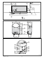
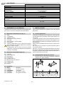
2.2 Gearedmotorreferences(g.2-3)
[9] Casing
[10] Control panel
[11] Motor
[12] Transformer
[13] Manual release
[14] Safety micro
[15] Base plate
[16] Line fuse
[17] Pinion
2.3 Accessories
[18] BATK3 Battery kit
[19] LUXK3E Courtesy light kit
[20] CROSSCRN2 Rack
[21] CROSS3TC Chain drive kit
[22] CROSS3SF Photocell support kit
3. INSTALLATION
Unless otherwise specied, all measurements are expressed
in millimetres (mm).
3.1 Preliminary checks
Check the stability of the wing (derailing and lateral falls) and
the sliding wheels and that the upper guides do not cause any
friction.
The sliding guide must be securely xed to the ground for the
full length within the doorway and must have no irregularities
that could hinder the movement of the gate.
The opening and closing stops must be tted.
Note: make sure that the gate can not exit the sliding guides
and fall.
If the gate has slits, make sure they are covered to prevent
shearing points.
Safety device should be installed at the end of the wing to reduce
the collision force.
3.2 Base plate position
- Insert the anchoring brackets into the base plate [15] and
secure them by means of the nuts provided.
1. TECHNICAL DATA
CROSS3E
Power supply 230 V~ / 50-60 Hz
Absorption 1.2 A
Thrust 150 N
Max run
7 m
5.7 m [CROSS3TC]
Openingspeed 0.12 - 0.25 m/s
Closingspeed 0.12 - 0.25 m/s
Acquisition speed 0.10 m/s
Maxdoorweight 300 kg
Service class 3 - FREQUENT
Min number of
consecutive cycles
50
Intermittence
S2 = 15 min
S3 = 50%
Temperature -20° C / +55° C
Degreeofprotection IP24D
Control panel 73RP
GB

CROSS3E - IP1780
13
- Lay a concrete foundation with buried anchoring brackets
and the base plate, making sure that it is pefectly level and
smooth, complying with the measurements show in gure.
If a concrete foundation is already available, secure the
base plate by means of appropriate dowels (not supplied)
so as to allow height adjustment.
Route the cable ducts through the right hole of the plate.
Note: if the cement area is already present, adjustable
SUPCS base can be used.
Attention: the gearmotor must be suitably raised from the
ground to avoid ooding.
3.3 Geared motor installation
- Release the gearmotor and remove the key. Loosen the
two front screws and remove the casing.
- Position the geared motor on to the base plate.
- Gearmotor adjustments
Horizontally by sliding in the ancoring feet notches (max
5 mm).
Vertically with the [3] levelling screws [B] (max 10 mm).
Note: while adjusting vertically, keep the motor slightly
raised above the base plate so as to allow enough space to
secure the rack and to make any subsequent adjustments,
if necessary.
3.4 Rack installation
- Release the gearmotor and set the gate in the open po-
sition. Place the rack on pinion [17] and move the gate
manually to secure the rack along its full length.
- Once the rack has been secured, vertically adjust the
geared motor so as to have a gap of 2 to 3 mm between
the pinion and the rack.
Attention: the weight of the gate must not bear on the
pinion, otherwise malfunctioning will result.
- Firmly secure the gearmotor with the nuts [A].
- Slightly lubricate the rack and pinion after assembly.
Manually check that the gate slides evenly and without
friction.
GB
OPENING
Ø50
Ø8,5
Ø7
100
80
X+5
(*)
40 (**)
70
220
200
min 60
160
OPENING
100
80
X+5
(*)
40 (**)
70
220
min 60
200
160
Ø7
Ø8,5
Ø50
(*)CROSSCRI X=40
(*)CROSSCRP X=30
(*)CROSSCRN2 X=40
(**)CROSS3TC
X
50
20
±5
±2,5
A
B
80
2÷3
17
F

CROSS3E - IP1780
14
4. ELECTRICAL CONNECTIONS
The electrical connections and starting are illustrated in the
installation manual of the control panel.
ATTENTION: Connect the yellow-green ground cable to the
clamp already connected to the motor, as it is shown in the
gure.
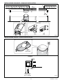
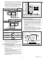
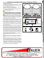
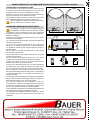
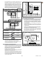
5. CROSS3SFINSTALLATION(fig.4)
Additional photocells can be installed inside the gear motor
utilising the optional CROSS3SF kit, so as to protect the closing
movement as well as the opening movement.
Assemble a receiver (RX) or a transmitter (TX) on the brackets
supplied, as shown in the gure.
Installation of the photocells must be carried out in observance
of the standards EN12453 and EN12445.
Attention: the photocell receiver (RX) and transmitter (TX) may
also be installed at two different heights, the maximum permis-
sible difference in height being 300 mm.
6. LUXK3EINSTALLATION(fig.5)
The LUXK3 kit permits to illuminate the area around the au-
tomatic gate for a period of 3 minutes upon the appropriate
command being given.
Secure the kit by means of the three screws provided and con-
nect to control panel as shown in the gure.
To route the leads inside the control panel, cut out the plastic
sheath at the marked spot (see LUXK3E instructions).
After the connections, mount the cover.
GB
3.5 CROSS3TC installation
- Remove the cover [F] and the retaining ring [G] and slide out
the pinion [17].
- Insert the pinion [L], the spacer [J] and fasten with the
seeger [G].
- Replace the cover [F].
- Secure the chain striker bracket [E].
3.6 Chain installation
- Release the geared motor (see OPERATING INSTRUC-
TIONS) and pass the chain between pinion [L] and stop
[E] by turning the pinion manually.
With the chain supplied, the gate has a maximum stroke
of 5.7 meters.
- Open the gate and attach brackets [C] to the leaf as shown
in gure.
- Connect the chain previously installed on the geared motor
to rod [D] and attach it to bracket [C].
- Attach the chain to the other side of the gate by means of
rod [D] and bracket [C] (cut off excess chain).
Note: with the gate in complete opening and closing posi-
tion, check that the distance between the center of pinion
[L] and rod [D] shown in gure is respected.
- Finally, rmly secure the geared motor by nuts [A].
- Tighten the chain with rods [D]. Lubricate the chain and
pinion lightly after assembly.
17 G F
G
E J
L
F
min
25
L
D
min 60
C
H
90÷10050
D
E LF
yellow-green

CROSS3E - IP1780
15
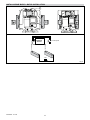
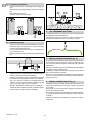
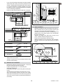
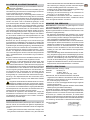
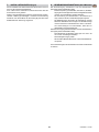
7. BATK3INSTALLATION(fig.6)
The BATK3 battery kit permits to operate the gate even in case
of mains power failure.
Note: when not in use, batteries are kept charged by means of
the control circuit.
Fit the batteries inside the geared motor and secure by means
of the appropriate support brackets. Connect as shown in the
gure.
The battery control circuit [M] can be snapped on into place
above the cooling n of the control panel.
GB
8. MAINTENANCEPROGRAM(every6months)
Disconnect the power supply and release the gearmotor (see
RELEASE INSTRUCTIONS):
- Visually check that the gate, the xing brackets and existing
structure have suitable mechanical strength and are in
good condition.
- Check the gate-gearmotor alignment, the distance (2-3
mm) between the throat of the pinion, the crest of the rack
and the distance between the rack and rack stop (3 mm)
if present.
- Clean the wheel’s sliding guide, the rack and pinion of the
gear motor and slightly lubricate the rack and pinion of the
gearmotor. Manually check that the gate slides evenly and
without friction.
Connect the power supply and block the gearmotor (see RE-
LEASE INSTRUCTIONS operations):
- Check that the limit switches are working correctly (the
gate should stop 20 mm before the stop).
- Check the power adjustment.
- Check that all control and safety functions are working
correctly.
Attention: For spare parts, see the spares price list.

RELEASE INSTRUCTIONS
In the event of a fault or power failure, insert the key and turn
it anticlockwise and completely open the hatch. Open the gate
manually.
Attention: opening the door, the unlock micro that activates the
total stop on the control panel is opened too.
To block the gate again, close the hatch, turn the key clockwise
and remove the key.
Warning: carry out the wings blocking and release with
the motor off.
GENERAL SAFETY PRECAUTIONS
The following precautions are an integral and essential part
of the product and must be supplied to the user.
Read them carefully as they contain important indications for
the safe installation, use and maintenace.
These instruction must be kept and forwarded to all possible
future user of the system.
This product must be used only for that which it has been ex-
pressely designed. Any other use is to be considered improper
and therefore dangerous.
The manufacturer cannot be held responsible for possible da-
mage caused by improper, erroneous or unresonable use.
Avoid operating in the proximity of the hinges or moving me-
chanical parts.
Do not enter the eld of action of the motorised door or gate
while in motion.
Do not obstruct the motion of the motorised door or gate as this
may cause a situation of danger.
Do not lean against or hang on to the barrier when it is moving.
Do not allow children to play or stay within the eld of action of
the motorised door or gate.
Keep remote control or any other control devices out of the reach
of children, in order to avoid possible involuntary activation of
the motorised door or gate.
In case of breakdown or malfunctioning of the product, discon-
nect from mains, do not attempt to repair or intervene directly
and contact only qualied personnel.
Failure to comply with the above may create a situation of
danger.
All cleaning, maintenance or repair work must be carried out by
qualied personnel.
In order to guarantee that the system works efciently and
correctly it is indispensable to comply with the manufacturer’s
indications thus having the periodic maintenance of the motori-
sed door or gate carried out by qualied personnel.
In particular regular checks are recommended in order to verify
that the safety devices are operating correctly. All installation,
maintenance and repair work must be documented and made
available to the user.
OPERATING INSTRUCTIONS FOR FOR SLIDING GATES AUTOMATION CROSS3E
ON
OFF
DITEC S.p.A.
Via Mons. Ban, 3
21042 Caronno Pertusella (VA) - ITALY
Tel. +39 02 963911 - Fax +39 02 9650314
www.ditec.it - [email protected]
TEAR OFF AND DELIVER TO USER
Installer:
Page is loading ...
Page is loading ...
Page is loading ...
Page is loading ...
Page is loading ...
Page is loading ...
Page is loading ...
Page is loading ...
Page is loading ...
Page is loading ...
Page is loading ...
Page is loading ...
Page is loading ...
Page is loading ...
Page is loading ...
Page is loading ...
Page is loading ...
Page is loading ...
Page is loading ...
Page is loading ...
Page is loading ...
Page is loading ...
Page is loading ...
Page is loading ...
Page is loading ...
-
 1
1
-
 2
2
-
 3
3
-
 4
4
-
 5
5
-
 6
6
-
 7
7
-
 8
8
-
 9
9
-
 10
10
-
 11
11
-
 12
12
-
 13
13
-
 14
14
-
 15
15
-
 16
16
-
 17
17
-
 18
18
-
 19
19
-
 20
20
-
 21
21
-
 22
22
-
 23
23
-
 24
24
-
 25
25
-
 26
26
-
 27
27
-
 28
28
-
 29
29
-
 30
30
-
 31
31
-
 32
32
-
 33
33
-
 34
34
-
 35
35
-
 36
36
-
 37
37
-
 38
38
-
 39
39
-
 40
40
-
 41
41


Bauer CROSS3E Installation and Maintenance Manual
- Category
- Gate Opener
- Type
- Installation and Maintenance Manual
Ask a question and I''ll find the answer in the document
Finding information in a document is now easier with AI
in other languages
- italiano: Bauer CROSS3E
- français: Bauer CROSS3E
- español: Bauer CROSS3E
- Deutsch: Bauer CROSS3E
- português: Bauer CROSS3E
Other documents
-
CAME BX241 User manual
-
-
 Roger Technology BRUSHLESS Smarty 5 User manual
-
 Roger Technology BRUSHLESS KIT BH30/605/HS User manual
-
Chamberlain SLY Series Owner's manual
-
Chamberlain LiftMaster SLY Series 24v Owner's manual
-
 DITEC CUBIC6TC Owner's manual
-
CAME BY-3500T User manual
-
-
 Roger Technology 230v SET R21/354 User manual


