Page is loading ...

The Dishwashing Machine Specialists
Technical Manual
Undercounter
Dishwasher
Model
U-HB
High Temperature
with Built-In Booster
U-H1
High Temperature
U-LD
Low Temperature
June, 1995
P.O. Box 4149
Winston-Salem, North Carolina 27115-4149
Champion Industries, Inc.
Manual P/N 111752-1
Champion
Fax: 336/661-1660336/661-1556
Machine Serial No.

Complete the information below so it will be available for quick reference.
Model Number __________________________ Serial Number________________________
Voltage and Phase ______________________________________________________________
Champion Parts Distributor __________________________________ Phone _____________
_____________________________________________________________________________
Champion Service Agency___________________________________ Phone _____________
_____________________________________________________________________________
Champion Industries Service: 1-800-858-4477 Champion Service Fax: 1-336-661-1660
We strongly recommend that you fax your orders.
NOTE: When calling to order parts, be sure to have the model number,
serial number, voltage, and phase of your machine.
COPYRIGHT © 1994, 1995 by Champion Industries, Inc.
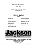
U-LD
U-H1/U-HB
Machine Data Plate
with
Model & Serial number
located on right side of
front panel.
Machine Data Plate
with
Model & Serial number
located on left side of
front panel.
Champion
Champion

Revision History
Revision Revised Serial Number Comments
Date Pages Effectivity
12/30/92 — 84299 Air Trap/Pressure Switch
changed to Float switch/
Fill Timer for automatic fill
and low water protection for
Models U-H1/U-HB
1/13/94 — 85680 Relocated final rinse
thermometer to back of machine,
added brass cross and barb fittings
1/1/95 — Issued Manual P/N 111752-1
which supercedes Manual P/N 111752
dated May, 1994. For machines
beginning with S/N 84299 and above
1/1/95 22 — Corrected Pump/Motor Removal
Instructions (Step 7)
1/1/95 23 — Added Door Switch and Magnet
to illustration
1/1/95 29 — Corrected Item #16, changed P/N
104741 to P/N 108349
1/1/95 30 — Added Solenoid Valve detail
1/1/95 33 — Corrected Item #14, changed P/N 104741
to P/N 108349
1/1/95 34 — Added Solenoid Valve detail
1/1/95 39 — Corrected Item #19, changed P/N 110210
to 110211
1/1/95 57 — Corrected Item #4, changed P/N 108265 to
P/N 107550, changed 1/2" to 3/4"
4/10/95 52-53 87075 Redesigned U-HB Booster Tank for machines
beginning with S/N 87075 and above
2/9/96 53 87724 Changed control thermostats to P/N 112204
REVISIONS

CONTENTS
Page
The Dishwashing Formula.........................................................................................................5
WARRANTY .............................................................................................................................6
INTRODUCTION......................................................................................................................7
GENERAL.................................................................................................................................8
Model Numbers...................................................................................................................8
Standard Equipment ............................................................................................................8
Options ................................................................................................................................8
Accessories..........................................................................................................................9
Electrical Power Requirements ...........................................................................................9
INSTALLATION........................................................................................................................9
Unpacking ..........................................................................................................................9
Electrical Connections.........................................................................................................10
Plumbing Connections.........................................................................................................10
Water Connections...............................................................................................................10
Drain Connections...............................................................................................................11
Chemical Connections.........................................................................................................12
Models U-H1 and U-HB...............................................................................................12
Model U-LD..................................................................................................................12
INITIAL START-UP..................................................................................................................13
Model U-H1 and U-HB.......................................................................................................13
Model U-LD........................................................................................................................13
OPERATION ..........................................................................................................................14
Model U-H1 and U-HB.......................................................................................................14
Model U-LD........................................................................................................................15
MAINTENANCE.......................................................................................................................16
Maintenance Schedule.........................................................................................................16
CLEANING ..................................................................................................................16
Every 2 Hours or After Each Meal Period.............................................................16
Model U-H1 and U-HB ...................................................................................16
Model U-LD.....................................................................................................16
Every 8 Hours or at the End of the Day.................................................................16
Model U-H1 and U-HB ...................................................................................16
Model U-LD.....................................................................................................17
DELIMING...................................................................................................................17
Deliming process....................................................................................................17
Model U-H1 and U-HB ...................................................................................17
Model U-LD.....................................................................................................18
OPERATION CHECKS................................................................................................18
Daily .......................................................................................................................18
Weekly....................................................................................................................18
2
CONTENTS

CONTENTS
Page
TROUBLESHOOTING.............................................................................................................18
BASIC SERVICE.......................................................................................................................20
Electrical Service.................................................................................................................20
Motor Connections........................................................................................................20
Timed Fill/Low Water Tank Heat Protection................................................................20
Mechanical Service..............................................................................................................21
Timer Cam Adjustments...............................................................................................21
Pump Seal Replacement ...............................................................................................22
U-HB Component Diagram ..........................................................................................23
REPLACEMENT PARTS LIST ................................................................................................24
ELECTRICAL SCHEMATICS .................................................................................................58
TIMER CHARTS.......................................................................................................................60
LIST OF FIGURES
Figure 1— Drain Connection U-H1/U-HB ..............................................................................11
Figure 2— Drain Connection U-LD.........................................................................................11
Figure 3— U-H1/U-HB Chemical Connection Points.............................................................12
Figure 4— Pump Motor Wiring Diagrams U-H1/U-HB/U-LD...............................................20
Figure 5— U-H1/U-HB Timer Chart........................................................................................21
Figure 6— U-LD Timer Chart..................................................................................................21
Figure 7— U-LD Timer Cam Locations ..................................................................................21
Figure 8— Pump Seal Replacement.........................................................................................22
Figure 9— Panels and Gauges..................................................................................................24
Figure 10—Door, Tracks, Safety Switch...................................................................................26
Figure 11—U-H1/U-HB Plumbing............................................................................................28
Figure 12—U-H1/U-HB Fill Solenoid Valve and Piping..........................................................30
Figure 13—U-LD Plumbing......................................................................................................32
Figure 14—U-LD Fill Solenoid Valve and Piping....................................................................34
Figure 15—U-LD Chemical Dispensing System......................................................................36
Figure 16—U-H1/U-HB Float Switch, Sump, Pump Hoses.....................................................38
Figure 17—U-LD Sump, Pump Hoses, Drain Assembly..........................................................40
Figure 18—U-H1/U-HB Wash Arm Assembly.........................................................................42
Figure 19—U-LD Wash Arm Assembly ...................................................................................44
Figure 20—Pump/Motor Assembly...........................................................................................46
Figure 21—U-H1/U-HB Control Cabinet .................................................................................48
Figure 22—U-LD Control Cabinet............................................................................................50
Figure 23—U-H1/U-HB Thermostats, Booster Assembly, Wash Tank Element......................52
Figure 24—U-H1/U-HB/U-LD Drain Lift Kits (Optional).......................................................54
Figure 25—Dishracks, Strainer, PRV........................................................................................56
Figure 26—U-H1/U-HB Electrical Schematic..........................................................................58
Figure 27—U-LD Electrical Schematic ....................................................................................59
Figure 28—Timer Charts (U-H1/U-HB) and U-LD..................................................................60
3
CONTENTS

4
NOTES
NOTES

The Dishwashing Formula
Five Elements for Cleaning Dishes
A Perfect Score means Clean Ware for your customers...
Peak Dishwasher Performance for you.
Point Value
1. Temperature......................................................................
20
Heated water penetrates and loosens soil on dishes.
2. Time ..................................................................................
20
Wash and rinse times (set by NSF and Champion) allow everything to work.
3. Mechanical Action............................................................ 20
Pumps produce water pressure which flushes the soil off dishes.
4. Chemical Action ...............................................................
20
Detergent breaks down grease and loosens soil particles.
5. Procedure..........................................................................
20
Pre-scraping and rinsing removes large food particles from the dishes.
SCORE 100
5

6
WARRANTY
LIMITED WARRANTY
Champion Industries Inc. (herein referred to as Champion), P.O. Box 4149, Winston-Salem, North Carolina 27115,
and P.O. Box 301, 2674 N. Service Road, Jordan Station, Canada L0R 1S0, warrants machines, and parts, as set out
below.
Warranty of Machines: Champion warrants all new machines of its manufacture bearing the name
“Champion” and installed within the United States and Canada to be free from defects in material and
workmanship for a period of one (1) year after the date of installation or fifteen (15) months after the date of
shipment by Champion, whichever occurs first. [See below for special provisions relating to glasswashers.] The
warranty registration card must be returned to Champion within ten (10) days after installation. If warranty card
is not returned to Champion within such period, the warranty will expire after one year from the date of
shipment.
Champion will not assume any responsibility for extra costs for installation in any area where there are
jurisdictional problems with local trades or unions.
If a defect in workmanship or material is found to exist within the warranty period, Champion, at its election,
will either repair or replace the defective machine or accept return of the machine for full credit; provided, how-
ever, as to glasswashers, Champion’s obligation with respect to labor associated with any repairs shall end
(a) 120 days after shipment, or (b) 90 days after installation, whichever occurs first. In the event that Champion
elects to repair, the labor and work to be performed in connection with the warranty shall be done during regular
working hours by a Champion authorized service technician. Defective parts become the property of Champion.
Use of replacement parts not authorized by Champion will relieve Champion of all further liability in connection
with its warranty. In no event will Champion’s warranty obligation exceed Champion’s charge for the machine.
The following are not covered by Champion’s warranty:
a. Lighting of gas pilots or burners.
b. Cleaning of gas lines.
c. Replacement of fuses or resetting of overload breakers.
d. Adjustment of thermostats.
e. Adjustment of clutches.
f. Opening or closing of utility supply valves or switching of electrical supply current.
g. Cleaning of valves, strainers, screens, nozzles, or spray pipes.
h. Performance of regular maintenance and cleaning as outlined in operator’s guide.
i. Damages resulting from water conditions, accidents, alterations, improper use, abuse,
tampering, improper installation, or failure to follow maintenance and operation procedures.
j. Wear on Pulper cutter blocks, pulse vanes, and auger brush.
Examples of the defects not covered by warranty include, but are not limited to: (1) Damage to the exterior or
interior finish as a result of the above, (2) Use with utility service other than that designated on the rating plate,
(3) Improper connection to utility service, (4) Inadequate or excessive water pressure, (5) Corrosion from
chemicals dispensed in excess of recommended concentrations, (6) Failure of electrical components due to
connection of chemical dispensing equipment installed by others, (7) Leaks or damage resulting from such
leaks caused by the installer, including those at machine table connections or by connection of chemical
dispensing equipment installed by others, (8) Failure to comply with local building codes, (9) Damage caused by
labor dispute.
Warranty of Parts: Champion warrants all new machine parts produced or authorized by Champion to be free
from defects in material and workmanship for a period of 90 days from date of invoice. If any defect in
material and workmanship is found to exist within the warranty period Champion will replace the defective
part without charge.
DISCLAIMER OF WARRANTIES AND LIMITATIONS OF LIABILITY
. CHAMPION’S WARRANTY
IS ONLY TO THE EXTENT REFLECTED ABOVE. CHAMPION MAKES NO OTHER WARRANTIES,
EXPRESS OR IMPLIED, INCLUDING, BUT NOT LIMITED, TO ANY WARRANTY OF
MERCHANTABILITY, OR FITNESS OF PURPOSE. CHAMPION SHALL NOT BE LIABLE FOR
INCIDENTAL OR CONSEQUENTIAL DAMAGES. THE REMEDIES SET OUT ABOVE ARE
THE EXCLUSIVE REMEDIES FOR ANY DEFECTS FOUND TO EXIST IN CHAMPION DISHWASHING
MACHINES AND CHAMPION PARTS, AND ALL OTHER REMEDIES ARE EXCLUDED,
INCLUDING ANY LIABILITY FOR INCIDENTALS OR CONSEQUENTIAL DAMAGES.
Champion does not authorize any other person, including persons who deal in Champion dishwashing
machines to change this warranty or create any other obligation in connection with Champion Dishwashing Machines.

INTRODUCTION
Welcome to Champion...
and thank you for allowing us to take care of your dishwashing needs.
This manual covers the undercounter series dishwasher models U-H1, U-HB, and U-LD.
Your machine was completely assembled, inspected, and thoroughly tested at our factory before
it was shipped to your installation site.
This manual contains:
• Warranty Information
• Operation and Cleaning Instructions
• Maintenance Instructions
• Troubleshooting Guide
• Basic Service Information
• Replacement Parts Lists
• Electrical Schematics
Complete and return your warranty registration card within ten (10) days after the
installation of your machine.
All information, illustrations and specifications contained in this manual are based
upon the latest product information available at the time of publication. Champion constantly
improves its products and reserves the right to make changes at any time
or to change specifications or design without notice and without incurring obligation.
For your protection, factory authorized parts should always be used for repairs.
Replacement parts may be ordered directly from Champion Industries* or
from your Champion authorized parts distributor or authorized service agency.
When ordering parts, please supply the model number, serial number, voltage,
and phase of your machine, the part number, part description and quantity.
*Champion Industries can only ship parts to customers by C.O.D.
7
INTRODUCTION

GENERAL
This manual covers the Champion undercounter dishwashing machine.
These machines are fully automatic and come equipped with a 3/4 HP pump motor.
All models are available for mounting directly to the floor or on optional stands.
The U-series dishwasher is available in the following models:
Model Numbers
U-H1, U-HB, U-LD
The U-H1 model is a high temperature (82°C/180°F rinse)
sanitizing model without booster.
The U-HB model is a high temperature (82°C/180°F rinse)
sanitizing model with booster.
The U-LD is a low temperature (Min. 49°C/120°F-60°C/140°F Optimum) sanitizing model for
use with a sodium hypochlorite (Chlorine) based sanitizer at a minimum concentration of
50PPM in the final rinse. A three pump chemical dispensing system for detergent, sanitizer and
rinse aid is included.
Standard Equipment includes:
U-H1 & U-HB U-LD
• Top mounted slide-out control cabinet • Top mounted slide-out control cabinet
• Common utility connections • Common utility connections
• Fully automatic wash & rinse cycle • Fully automatic wash & rinse cycle
• Self-sealing gasketless door • Self-sealing gasketless door
• Door safety switch • Door safety switch
• Upper & lower wash/rinse arms • Upper & lower wash/rinse arms
• 90 second time cycle • 150 second time cycle
• Electric tank heater • Three built-in chemical dispensing
• Low water tank heat protection pumps
• 3/4HP (208-240V/60/1) wash motor • 3/4HP (115V/60/1) wash motor
• Stainless steel heavy gauge construction, • Stainless steel heavy gauge construction,
including base including base
• Two dish racks (peg and flat bottom) • Two dish racks (peg and flat bottom)
• Built-in electric booster heater (U-HB Only) • 1-1/4” I.D. GRAVITY drain connection
(4°C/40°F temperature rise)
• 1-1/4” I.D. GRAVITY drain connection
Options
Electric booster (21°C/70°F temperature rise ) heater for
43°C/110°F supply water (U-HB only) N/A
Pumped drain lift-out Kit (U-H1 and U-HB) P/N 403898
Drain lift kit (U-LD) P/N 403801
P-Trap (U-H1 and U-HB) P/N 403836
Unmounted Pressure Regulating Valve (3/4” PRV) P/N 107550
1-1/4” flexible drain hose (order by the foot) P/N 111032
8
GENERAL

Accessories
Combination 1-RDT table w/ cabinet and sink (specify right hand or left hand sink)
Optional sprayhose for 1-RDT P/N 100243
Wall overshelf for 1-RDT (holds two racks) P/N 108189
16” Stainless steel stand P/N 305222
6” Stainless steel leg set (Qty.4) P/N 305221
Additional dishracks:
Dish rack (peg) P/N 101285
Silverware rack (flat bottom) P/N 101273
Electrical Power Requirements
Model Voltage Booster Rise Machine Power Requirement
(U-HB Only) Full Load Amps (125% Service Factor)
U-H1 208/60/1 — 12 Amps 15 Amps
U-H1 220/60/1 — 11 Amps 14 Amps
U-H1 230/60/1 — 11 Amps 14 Amps
U-H1 240/60/1 — 11 Amps 14 Amps
U-HB 208/60/1 40°F 44 Amps 55 Amps
U-HB 220/60/1 40°F 44 Amps 55 Amps
U-HB 230/60/1 40°F 46 Amps 58 Amps
U-HB 240/60/1 40°F 48 Amps 60 Amps
U-HB 208/60/1 70°F 58 Amps 73 Amps
U-HB 220/60/1 70°F 60 Amps 75 Amps
U-HB 230/60/1 70°F 62 Amps 76 Amps
U-HB 240/60/1 70°F 64 Amps 80 Amps
U-LD 115/60/1 — 12 Amps 15 Amps
INSTALLATION
Unpacking
CAUTION:
Care should be taken when lifting the machine to prevent damage.
1. Immediately after unpacking the machine, inspect for any shipping damage.
If damage is found, save the packing material and contact the carrier immediately.
2. Remove the dishwasher from the skid. Adjust the feet if required, then move the
machine to its permanent location.
3. Level the machine (if required) by placing a level on the top of machine
and adjusting the feet. Level the machine front-to-back and side-to-side.
4. Remove the two dishracks from the interior of the machine.
5. Remove the lower access panel in preparation for service connections.
9
INSTALLATION
!

INSTALLATION (Cont.d)
NOTE:
The installation of your machine must meet local health codes.
Some locales may require the base of the machine to be sealed at the floor.
Electrical Connections
WARNING:
Electrical and grounding connections must comply with the National Electrical Code
and/or Local Electrical Codes.
WARNING:
When working on the dishwasher, disconnect the electric service and place a tag at the
disconnect switch to indicate work is being done on that circuit.
1. A qualified electrician must compare the electrical power supply with the machine
electrical specifications stamped on the MACHINE ELECTRICAL CONNECTION
PLATE located inside the top mounted control cabinet before connecting to the incoming
service at a fused disconnect switch.
NOTE:
U-H1 and U-HB models require a 208-240V/60Hz/1PH,
2-wire plus ground electrical supply.
U-LD model requires a 115V/60Hz/1PH ,
2-wire plus ground electrical supply.
2. A knock-out is provided at the rear of the top mounted slide-out control cabinet for the
electrical service connection. A fused disconnect switch or circuit breaker (supplied by
others) is required to protect each power supply circuit.
NOTE:
INSTALLER SHOULD PROVIDE SUFFICIENT CABLE TO ALLOW TOP MOUNTED
SLIDE-OUT CONTROL CABINET TO EXTEND FULLY.
Plumbing Connections
CAUTION:
Plumbing connections must comply with local sanitary and plumbing codes.
Water Connections
1. HOT WATER connection can be made to the machine via the 6 foot reinforced
fill hose supplied with the machine. The fill hose is equipped with a 3/4” NPT connector
and exits the back of the machine.
2. Minimum incoming water supply temperature requirements are listed below
U-HB with built-in 40° rise electric booster (Minimum 60°C/140°F)
(Min./Max. flow pressure 138 kPa/20-22 PSI)
U-HB with built-in 70° rise electric booster (Minimum 43°C/110°F)
(Min./Max. flow pressure 138 kPa/20-22 PSI)
10
INSTALLATION
!
!
!

Water Connections (Cont.d)
U-H1 without built-in booster (Minimum 70°C/180°F)
(Min./Max. flow pressure 138 kPa/20-22 PSI)
U-LD (Minimum 49°C/120°F - 60°C/140°F Optimum)
(Min./Max. flow pressure 138 kPa/20-22 PSI)
3. A manual shut-off valve (supplied by others) should be installed in supply line to allow for
servicing of the machine.The shut-off valve should be the same size
or larger than the supply line.
4. A “Y” line strainer (supplied by others) is recommended on the incoming water supply line
as close to machine as possible, but before the pressure regulating valve.
5. A 3/4” Pressure Regulating Valve (PRV),(supplied by others), should be installed on the
incoming water supply line if water flow pressure exceeds 138 kPa/20-22 PSI.
Drain Connections
1. Models U-H1, U-HB, and U-LD are GRAVITY DRAIN machines equipped
with a 1-1/4” hose connection point.
• Drain height for models U-H1 and U-HB must not exceed 4-1/2” above floor level.
• Drain height for model U-LD must not exceed 7-1/2” above floor level.
NOTE:
For drain heights in excess of those listed above,
OPTIONAL drain lift kits are available (See Options, Pg.8)
WARNING:
Connection of the machine to a drain line higher than the machine drain height
will prevent the machine from draining properly.
Refer to Figure 1 and 2 below for machine drain connection locations.
Figure 1 Figure 2
1-1/4” Drain Connection 1-1/4” Drain Connection
U-H1/U-HB U-LD
Rear View of Machine Rear View of Machine
11
INSTALLATION
!
Drain Connection
Drain Connection

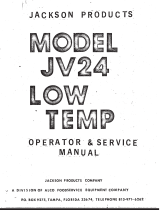
Chemical Connections
NOTE:
Consult a qualified chemical supplier for your chemical needs.
Models U-H1 and U-HB
1. Labeled connection points (See Fig. 3) are provided inside the
control cabinet for chemical dispensing equipment (supplied by others).
Connection points include:
• Detergent signal 208-240VAC
between Wire #7 and Wire #2 .
(1 Amp Max Amperage Draw)
• Rinse aid signal 208-240VAC
between Wire #8 and Wire #2
(1 Amp Max Amperage Draw)
Figure 3
U-H1/U-HB Chemical Connection Points
2. Detergent injection point and location of conductivity cell must be provided
by a qualified chemical supplier.
3. Detergent may be added manually for U-H1/U-HB models not equipped with dispensing
systems. Consult your local chemical supplier for the correct amount
of non-c
hlorinated automatic dishwashing liquid detergent.
4. U-H1 and U-HB models do not require chemical sanitizing agents.
5. Rinse aid injection point is provided via a 1/2” NPT plug located in the fill manifold
piping The manifold is located after the fill solenoid valve on the center right side of the
machine base behind the gauges.
Model U-LD
1. Equipped with three built-in dispensing pumps for detergent, sanitizer, and rinse aid.
Pump Priming switches are located on the front of the control cabinet.
(See U-LD Initial Start-up for pump priming instructions, (Pg. 13, Step 10).
(See U-LD Service for timer cam settings and adjustments, (Pg. 21)
2. Chemical pick-up tubes are color coded.
• Red = detergent Blue = Rinse aid Clear = Sanitizer
Chemicals are supplied by others.
3. Use an automatic commercial grade liquid detergent.
Use a sodium hypochlorite (Chlorine) based sanitizer at a minimum concentration of
50PPM in the final rinse.
Use chlorine test papers to verify and monitor the 50PPM chlorine level.
4. Use a liquid rinse aid.
WARNING:
Never premix rinse aid with the sanitizing agent. Mixing may cause hazardous gases to form.
CAUTION:
Some metal, including silver, aluminum, and pewter are attacked by sodium hypochlorite
(chlorine sanitizer). Avoid cleaning these metals in a U-LD dishwasher.
12
INSTALLATION
!
!
Rinse Aid
Detergent

INITIAL START-UP
After plumbing and electrical connections are completed,
follow the steps below to place your machine in service.
Model U-H1 and U-HB
1. Remove any foreign material from inside the machine.
Make sure filter, and drain-overflow tube are in place.
2. Close the Door.
3. Turn the water and main power sources to the dishwasher ON.
4 Flip the Power switch to the ON position. The red “power on” light will illuminate and the
machine will automatically fill with water.
5. Check the machine for leaks.
6. Push the Green Start Button to check automatic cycle. Check for leaks.
7. If machine checks okay, remove the drain-overflow tube to drain machine.
8. Flip the power switch to OFF.
Model U-LD
1. Remove any foreign material from inside the machine. Make sure filter, is in place.
2. Close the Door.
3. Turn the water and main power sources to the dishwasher ON.
4 Flip the Power switch to the ON position. The red “power on” light will illuminate.
5. Hold the Fill switch in the “UP” position for about 45 sec. to fill the machine with water.
Machine is full when water level reaches drain overflow located at lower left rear corner
of wash tank interior.
6. Check the machine for leaks.
7. Prime the chemical dispensing pumps.
NOTE:
The pick-up tubes are color coded:
Red = detergent Blue = rinse aid Clear = sanitizer
8. Insert the pick-up tubes in the appropriate chemical containers.
9. Open the door of the machine.
10. Hold each of the three prime switches, located on the front of the control cabinet in the
“UP” position until you see chemical enter the tank interior from all three tubes.
NOTE:
The chemical tubes discharge point is on the right side of the wash tank ceiling.
11. The chemical dispensing system will work automatically until the chemical supply is
used up. Re-prime the dispensing pump after replacing a chemical container.
12. Close the door.
13. Push the the Green start button to check the automatic cycle. Check for leaks.
14. If machine checks okay, hold the drain switch in the “UP” position
until machine drains completely.
15. Flip the power switch to OFF.
13
INITIAL START-UP

OPERATION
Model U-H1 and U-HB
1. Close the door and flip power switch ON Red power light illuminates.
Tank fills automatically and
tank heat comes on
2. Monitor wash tank temperature gauge Wait for temperature reading to reach
Minimum 66°C/150°F
3. Prescrap and load ware into rack Place dishes edgewise in peg rack,
Cups and bowls upside down in flat rack,
Silverware spread evenly in single layer
in flat rack
4. Open door , insert rack
5. Close door, Push Green start button Green cycle light will illuminate
Automatic cycle begins.
Machine washes for 67 sec., then
pauses for 2 sec
6. During final Rinse Machine final rinses for 21 sec.
Monitor pressure gauge and Pressure gauge reading must read
final rinse temperature gauge between 20-22 PSI
Temperature gauge must read
82-91°C/180-195°F
7. 90 second cycle complete Green cycle light goes out
8. Open door, remove clean rack Insert another rack of soiled ware
9. After each meal period or Remove drain-overflow tube and drain
every two hours operation machine. Flush interior and clean sump
filter and pump intake strainer. Check
spray arms and clean if necessary
NOTE:
Opening the door at any time during the cycle will stop the machine.
Closing the door and pushing the Green start button will resume the cycle where it left off.
14
OPERATION

Model U-LD
1. Close the door and flip power switch ON Red power light illuminates
2. Hold the Fill switch in “UP” position Wash tank fills with water
for about 45 sec.
3. Monitor wash tank temperature gauge Temperature reading must be
Min. 120°F/140°F Optimum
4 Prescrap and load ware into rack Place dishes edgewise in peg rack,
Cups and bowls upside down in flat rack,
Silverware spread evenly in single layer
in flat rack
5. Open door , insert rack
6. Close door, Push Green start button Green cycle light will illuminate
Automatic cycle begins.
Machine washes for 62 sec., then
Drains and refills for 56 sec.
7. Monitor temperature gauge Machine final rinses for 32 sec.
Temperature gauge must read a
If wash temperature drops below 120°F, (Minimum 120°-140° F Optimum)
Drain and refill machine.
8. 150 second cycle complete Green cycle light goes out
9. Open door, remove clean rack Insert another rack of soiled ware
10. After each meal period or Hold drain switch in “UP position and
every two hours operation drain machine. Flush interior and clean
filter and strainer plate. Drain again. Check
spray arms and clean if necessary.
NOTE:
Opening the door at any time during the cycle will stop the machine.
Closing the door and pushing the Green start button will resume the cycle where it left off.
15
OPERATION

MAINTENANCE
Cleaning your machine is the best maintenance that you can provide. Components that are not
regularly flushed and cleaned do not perform well.
The Maintenance intervals shown in the following schedules are the minimum requirements
necessary for the proper performance of your machine. Maintenance intervals should be
shortened whenever your machine is faced with abnormal working conditions, hard water, or
multiple shift operations.
Maintenance Schedule
CLEANING
• Every 2 Hours or After Each Meal Period
Model U-H1 and U-HB
1. Flip the power switch OFF.
2. Remove the drain-overflow tube, drain the machine.
3. Flush tank interior with fresh water.
4. Remove and clean the sump filter and pump intake screen.
5. Inspect the spray arm nozzles and clean if necessary.
6. Close door, flip power switch ON to refill machine.
Model U-LD
1. Hold drain switch in “UP” position until tank drains completely.
2. Flip power switch to OFF.
3. Flush tank interior with fresh water.
4. Drain machine again.
5. Remove and clean the sump filter and strainer plate.
6. Inspect the spray arm nozzles and clean if necessary.
7. Close door, flip power switch ON.
8. Hold fill switch in “UP” position to refill machine.
• Every 8 Hours or at the End of the Day
Model U-H1 and U-HB
1. Flip the power switch OFF.
2. Remove the drain-overflow tube, drain the machine.
3. Flush tank interior with fresh water.
4. Remove the sump filter and pump strainer.
5. Remove the spray arms.
6. Clean and inspect the spray arm bearings.
7. Remove the spray arm end plugs by twisting counter-clockwise and pulling.
8. Flush the spray arm pipes and nozzles.
9. Replace the end plugs.
10. Back flush the sump filter and pump intake strainer.
11. Thoroughly clean the exterior of the machine. DO NOT HOSE DOWN WITH WATER.
12. Reassemble the machine. Leave the door open to aid overnight drying.
CAUTION:
DO NOT LEAVE WATER IN WASH TANK OVERNIGHT
16
MAINTENANCE
!

Cleaning (Cont.d)
Model U-LD
1. Hold drain switch in “UP” position until tank drains completely.
2. Flip power switch to OFF.
3. Flush tank interior with fresh water.
4. Remove the sump filter and strainer plate.
5. Remove the spray arms.
6. Clean and inspect the spray arm bearings.
7. Remove the spray arm end plugs by twisting counter-clockwise and pulling.
8. Flush the spray arm pipes and nozzles.
9. Replace the end plugs.
10. Back flush the sump filter and strainer plate
11. Thoroughly clean the exterior of the machine. DO NOT HOSE DOWN WITH WATER.
12. Reassemble the machine. Leave the door open to aid overnight drying.
CAUTION:
DO NOT LEAVE WATER IN WASH TANK OVERNIGHT
DELIMING
Your dishwasher should be delimed regularly depending on the mineral content of your water.
Inspect the machine interior for mineral deposits and use a deliming solution
for the best cleaning results.
NOTE:
Consult your chemical supplier for an appropriate deliming solution.
WARNING:
Deliming solutions or other acids must not come in contact with household bleach
(sodium hypochlorite) or any chemicals containing chlorine, iodine, bromine, or fluorine.
Mixing will cause hazardous gases to form.
Skin contact with deliming solutions can cause severe irritation and possible chemical
burns. Consult your chemical supplier for specific safety precautions.
DELIMING PROCESS
Model U-H1 and U-HB (Not equipped with chemical dispensing system)
1. Remove all dishes from machine.
2 Drain the machine and refill with fresh water.
3. Spray interior walls with delimimg solution and let sit for 5 or 10 minutes
depending on amount of build-up. Add deliming solution to wash tank.
Do not let chemicals sit for longer than 15 minutes.
4. Push the Green start button and run an automatic cycle.
5. Repeat Step 3-4 if necessary.
6 Remove the drain-overflow tube and drain the machine.
7. Refill the machine and run a complete cycle two additional times.
Drain and refill the machine after each cycle to thoroughly flush any
deliming solution from the interior of the machine.
8. Flip the power switch to OFF.
9. Drain Machine.
10. Deliming is complete.
17
MAINTENANCE
!
!

DeLiming Process (Cont.d)
Model U-LD
1. Remove all dishes from machine.
2. Remove the chemical pick-up tubes from their containers.
3. Place each tube in a container of fresh water and hold each prime switch in the “UP”
position several minutes to thoroughly flush chemical from the lines. Leave pick-up
tubes out of their containers.
4. Hold the drain switch in the “UP” position to drain the machine.
5. Refill the machine with fresh water and drain again. Then refill with water.
6. Spray interior walls with deliming solution and let sit for 5 or 10 minutes depending on
amount of build-up. Add deliming solution to wash tank.
Do not let chemicals sit for longer than 15 minutes.
7. Push the Green start button and run an automatic cycle.
8. Repeat Step 3-6 if necessary.
9. Hold the drain switch in the “UP” position to drain the machine.
10. Refill the machine and run a complete cycle two additional times.
Drain and refill the machine after each cycle to thoroughly flush any
deliming solution from the interior of the machine.
11. Replace the pick-up tubes in their chemical supplies and reprime the system.
12. Flip the power switch to OFF.
13. Deliming is complete.
OPERATION CHECKS
• Daily
1. Check temperature gauges for proper readings.
2. Check pressure gauge for proper reading (U-H1, U-HB ONLY).
3. Check for leaks.
4. Check chemical supplies and refill as necessary.
• Weekly
1. Inspect all water lines for leaks.
2. Clean all detergent residue from the exterior of the machine.
3. Check the drains for leaks.
4. Clean accumulated mineral deposits from the tank heating elements (U-H1, U-HB ONLY)
5. Check that float switch moves freely (U-H1,U-HB ONLY).
6. Check and clean chemical dispensing system (U-LD ONLY).
TROUBLESHOOTING
On occasion your machine may not operate as expected.
Use the checklist below before you decide that a mechanical or electrical failure has occurred.
Checklist
1. All switches are ON?
2. Water supply ON?
3. Drain-overflow tube in place? (U-H1 and U-HB Only)
4. Spray arms and nozzles clean?
5. Spray arm end plugs in place?
6. Sump filter, pump strainer clean?
7. Thermostats set correctly? (U-H1, U-HB Only)
8. Door fully closed?
9. Chemical supplies filled?
18
TROUBLESHOOTING
/