FIBER
© 2017 Wirepath™
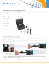
WP-CNTR-FBR-SC-MM10 Fiber Connector Termination
Follow this guide to terminate Wirepath™ Fiber SC connectors on SSF™ cable using Wirepath Fiber tools.
I. Compatibility and Features
• Unique termination method eliminates the need for any polishing or cleaning of the ber.
• Compatible with the following Wirepath SSF™ bulk cables:
• SP-FBR-PL-1K-SMM/DMM – SSF Simplex and Duplex Multimode OM3 50/125 3mm Plenum Fiber
• SP-FBR-R-1K-SMM/DMM – SSF Simplex and Duplex Multimode OM3 50/125 3mm Riser Fiber
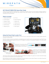
II. Required Termination Tools (WP-TOOL-KIT-FIBER or WP-TOOLKIT-FIBER-BAS/PRO)
• Fiber Cleaver
• Visual Fault Locator (VFL)
• Cable Stripper Tool
• Cable Scissors
• Measuring Tool
Note: All Wirepath Fiber Cleavers come pre-adjusted for cleaving Wirepath SSF ber. Other ber cleaver tools might require
adjustment of the cutting wheel to work properly.
III. Connector Breakdown
Threaded Boot Connector Body Connector Cover Dust Cap
Note: Keep the dust cap in place whenever possible to avoid damage to the end of the connector.
I V. Using the Visual Fault Locator (VFL) Tool
The VFL tool shines a laser through the connector and veries proper ber alignment during assembly based on the
brightness of the light seen through the activator slide tab.
Bright light in the activator slide
tab indicates ber is not present/
aligned correctly in the connector.
Light dims in the activator slide tab
once the ber is correctly aligned
inside the connector.
Note: Your tool kit may include a different model VFL tool. Basic operation is the same.

FIBER
Slide the threaded boot on the end
of the cable, then cut the ber jacket
back 2" using the strippers.
Using your ngernails, scrape the soft
peel coating, leaving 12mm of coating
between the jacket and the exposed
ber. *Important: Do not use strippers
to remove the soft peel coating.
Open the cleaver. Align the end of the
jacket at the 28mm mark, close the
top, then quickly push the button( )
to complete the cut.
1
4
2
5
3
6
7 8
Measure the ber. A properly cleaved
end measures 28mm from the jacket
to the tip of the ber (12mm of coating
and 16mm of bare ber).
Remove the connector from the VFL
and replace the dust cap. Fold the
Kevlar strands to one side and close
the clamshell.
Push the ber into the connector
opening until it bends slightly and the
VFL light dims, then push the activator
slide tab ( ) over to lock the ber in
place.
Thread the coonector boot on enough
to catch the Kevlar strands, then trim
the strands and thread the boot on the
rest of the way.
Replace the connector cover.
Termination is complete!
Remember to leave the dust cap in
place until the connector is plugged in.
Technical Support: p. 866.838.5052 Ver.170124-2227
V. Terminating the Connector
NO STRIPPERS
Outer
Jacket
Soft Peel
Coating
Bare
Fiber
12mm 16mm
Scan the QR code to see instructional
videos for all Wirepath Fiber products.
/


