
Universal Compressor Start Kit (No. 912933)
ABOUT THE START KIT
This compressor start kit includes the following items:
Description Quantity
Compressor Start Assy ............................1
Mounting Brackets ....................................2
Plastic Tie-Wrap .......................................1
Screws ......................................................4
Installation Instructions .............................1
Start Kits are designed to provide additional starting
torque for air conditioners or heat pumps equipped with
compressors using a permanent split capacitor (PSC)
single phase motor. This type of motor does not require a
start kit under normal operating conditions, but, because
low starting torque is inherent with PSC motors, special
conditions such as low voltage and exceptionally high
operating temperatures, short thermostat cycles, etc.,
can interfere with compressor starting.
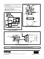
• ForSinglePackageSeriesAirConditionersandHeat
PumpsusetheverticalbracketasshowninFigure2.
• For Single Package Gas/Electric Models, use the
horizontalbracketasshowninFigure3.
• ForSplitSystemAirConditionersandHeatPumpsno
bracket is necessary.
INSTALLATION SEQUENCE
1. IMPORTANT! Turn the power off to the unit.
2. Decide which application is required for the unit. The
starting relay is position sensitive and is marked UP on
the side of the relay. Make sure the relay is mounted
sothatUPfacesupward.SeeFigures1-3forproper
relay orientation.
3. Removethecontrolpanelcover.
4. Attach the kit to the designated location in the control
panelwiththeprovidedscrews.Forsplitsystemunits,
mount capacitor and relay at the designated locations
inside the control panel. NOTE: This relay is equipped
with a universal bracket. With a pair of pliers, break
off any portion of the bracket that prevents proper
installation.
5. Attach the compressor start assembly to the proper
bracket using the capacitor strap and provided screws.
NOTE:Forsplitsystemunits,omitthisstep.
6. Connect the BLACKwire(Figure1)fromTERMINAL
5 on the start relay to T2 on the contactor.
7. Connect the RED wire from TERMINAL 2 on the start
relay to the compressor capacitor terminal marked H
(orHERM).
8. Connect the YELLOW wire from one terminal of the
start capacitor to the compressor capacitor terminal
marked C (or COMMON). NOTE: Terminals 4 & 6 are
not used for this application.
ELECTRICAL SHOCK, FIRE OR
EXPLOSION HAZARD
Failure to follow safety warnings exactly could
result in serious injury or property damage.
Improper servicing could result in dangerous
operation, serious injury, death or property
damage.
• Before servicing, disconnect all electrical
power to furnace.
• Whenservicingcontrols,labelallwiresprior
to disconnecting. Reconnect wires correctly.
• Verifyproperoperationafterservicing.
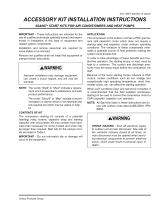
WARNING:
INSTALLATION INSTRUCTIONS
IMPORTANT SAFETY INFORMATION
These instructions are primarily intended to assist
qualified individuals experienced in the proper
servicing of heating and air conditioning appliances.
Some local codes require licensed installation / service
personnel for this type equipment. Use of this kit must
beinaccordancewiththeseinstructionsandwithall
applicablenationalandlocalcodesandstandards.
INSTALLER: Please read all instructions thoroughly
before servicing this equipment. Pay attention to all safety
warnings and any other special notes highlighted in the
manual. Safety markings are used frequently throughout
this manual to designate a degree or level of seriousness
and should not be ignored.
WARNING - Indicates a
potentially hazardous situation that if not avoided, could
result in personal injury or death. CAUTION - Indicates
a potentially hazardous situation that if not avoided, may
result in minor or moderate injury or property damage.
WARNING:
The safety information listed in this manual must
befollowedduringtheinstallation,service,and
operation of this unit. Unqualified individuals
should not attempt to interpret these instructions
or install this equipment. Failure to follow safety
recommendations could result in possible
damage to the equipment, serious personal
injury or death.

9. Routethestartingkitwiresalongthesideoftheexisting
wiring and tie-wrap all of the wires together with the
provided tie-wrap.
10. After installing the compressor start kit, place the
enclosed wiring diagram on the control panel cover
next to the unit wiring diagram.
11.Replacethecontrolpanelcover.
12.Restorepowerto theunit andcheckunit operation
with the start kit installed.
7094120 (Replaces707391A)
Specifications & illustrations subject to change without notice or incurring obligations.
O'FallonMO(03/12)
Figure2.VerticalBracketInstallation
4
2
1
3
6
To Run
Capcitor (H)
RED
BLACK
5
Capacitor (H)
Capacitor Strap
To Run
Capcitor (C)
YELLOW
To Contactor
(T2)
BLACK
Vertical
Bracket
Field Wiring
L1
L2
T1
T2
Capacitor
BLACK
Start
Relay
Run Capacitor
RED
YELLOW
C
H
Contactor
BLACK
4
5
2
1
6
4
5
2
1
3
6
3
Figure 1. Wiring Diagram
4
5
2
1
3
6
To Run
Capacitor (H)
To Contactor (T2)
Capacitor (H)
To Run
Capacitor (C)
RED
YELLOW
BLACK
BLACK
Capcitor Strap
Horizontal Bracket
Figure 3. Horizontal Bracket Installation
INSTALLER: Leave these instructions with the equipment owner.
-
 1
1
-
 2
2


Broan Universal Compressor Start Kit (No. 912933) Installation guide
- Type
- Installation guide
- This manual is also suitable for
Ask a question and I''ll find the answer in the document
Finding information in a document is now easier with AI
Related papers
-
Broan JT4BF Installation guide
-
-
Broan FSA1BF Installation guide
-
Broan FS4BF- (3t KB 2,4,5t KC) Installation guide
-
Westinghouse JS4BF-K(A,B) Installation guide
-
-
-
-
-
Other documents
-
 Coleman Evcon BPCH0361BA Installation guide
-
Danfoss Maneurop NTZ series - GB - US User guide
-
-
-
-
-
Amana GSX140191 User guide
-
 GOODMAN B13400312S Operating instructions
-
York International YCJD36S41S1 Installation guide
-
 GOODMAN VSX140181 User guide


