
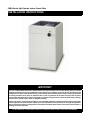
C6BA Series Split System Indoor Cased Coils
IMPORTANT
It is your responsibility to know this product better than your customer. This includes being able to install the
product according to strict safety guidelines and instructing the customer on how to operate and maintain the
equipment for the life of the product. Safety should always be the deciding factor when installing this product
and using common sense plays an important role as well. Pay attention to all safety warnings and any other
special notes highlighted in the manual. Improper installation of the furnace or failure to follow safety warnings
could result in serious injury, death, or property damage.
These instructions are primarily intended to assist qualified individuals experienced in the proper installation
of this appliance. Some local codes require licensed installation/service personnel for this type of equipment.
Please read all instructions carefully before starting the installation. Return these instructions to the customer’s
package for future reference.
DO NOT DESTROY. PLEASE READ CAREFULLY & KEEP IN A SAFE PLACE FOR FUTURE REFERENCE.
INSTALLATION INSTRUCTIONS

2
IMPORTANT SAFETY INFORMATION
Please read all instructions before servicing this equipment.
Pay attention to all safety warnings and any other special
notes highlighted in the manual. Safety markings are used
frequently throughout this manual to designate a degree or
level of seriousness and should not be ignored. WARNING
indicates a potentially hazardous situation that if not avoided,
could result in personal injury or death. CAUTION indicates a
potentially hazardous situation that if not avoided, may result
in minor or moderate injury or property damage.
WARNING:
NITROGEN
HEALTH
FLAMMABILITY
REACTIVITY
0 Minimal Hazard
1 Slight Hazard
1
0
0
C6 coils are pressurized with nitrogen at the
factory. Avoid direct face exposure or contact
with valve when gas is escaping. Always ensure
adequate ventilation is present during the
depressurization process. Any uncertainties
should be addressed before proceeding.
PROPOSITION 65 WARNING:
WARNING: This product contains chemicals known
to the state of California to cause cancer.
WARNING: This product contains chemicals known
to the state of California to cause birth defects or
other reproductive harm.
WARNING:
Improper installation, service, adjustment, or
maintenance may cause explosion, fire, electrical
shock or other hazardous conditions which may
result in personal injury or property damage. Unless
otherwise noted in these instructions, only factory
authorized kits or accessories may be used with
this product.
WARNING:
This unit must be installed in accordance with
the instructions outlined in this manual during
the installation, service, and operation of this
unit. Unqualified individuals should not attempt
to interpret these instructions or install this
equipment. If you do not posses mechanical skills
or tools, call your local dealer for assistance. Under
no circumstances should the equipment owner
attempt to install and/or service this equipment.
Failure to follow safety recommendations could
result in possible damage to the equipment, serious
personal injury or death.
• The installer must comply with all local codes and regulations
which govern the installation of this type of equipment.
Local codes and regulations take precedence over any
recommendations contained in these instructions. Consult
local building codes for special installation requirements.
• Familiarize yourself with the controls that shut off the
electrical power to the unit. If the unit needs to be shut down
for an extended period of time, turn off electrical power
at the circuit breaker. For your safety always turn off the
electrical power before performing service or maintenance
on the unit.
• Installation of equipment may require brazing operations.
Installer must comply with safety codes and wear
appropriate safety equipment (safety glasses, work gloves,
fire extinguisher, etc.) when performing brazing operations.
• Read the Installation Instructions supplied with the furnace
or air handler. Always observe all safety requirements
outlined in this manual and on the furnace or air handler
markings before installing the coil.
• Follow all precautions in the literature, on tags, and on
labels provided with the equipment. Read and thoroughly
understand the instructions provided with the equipment
prior to performing the installation and operational checkout
of the equipment.
• Use caution when handling this equipment or removing
components. Personal injury can occur from sharp metal
edges present in all sheet metal constructed equipment.

3
COIL INSTALLATION
WARNING:
ELECTRICAL SHOCK, FIRE OR
EXPLOSION HAZARD
Failure to follow safety warnings exactly could result
in serious injury or property damage.
Improper servicing could result in dangerous
operation, serious injury, death or property damage.
• Before servicing, disconnect all electrical power
to the equipment.
• When servicing controls, label all wires prior to
disconnecting. Reconnect wires correctly.
• Verify proper operation after servicing.
CAUTION:
The coil must be level to ensure proper condensate
drainage. An unlevel installation may result in
structural damage, premature equipment failure,
or possible personal injury.
General Information
C6 Series indoor cased coils are designed for upflow,
downflow, or horizontal applications when used in conjunction
with a horizontal drain pan kit. Accessory kits are not required
for factory ready horizontal coils. See Table 1, (page 7)
or Table 2, (page 7). Coils are equipped with braze type
refrigerant connections for easy installation.
• Check the coils orifice size and confirm that it’s suitable
for application with the intended outdoor unit. Depending
on application, additional installer supplied orifice or TXV
may be required.
• Optional cooling/heating equipment must be properly sized
and installed in accordance with the furnace manufacturer’s
specifications and approved recommendations.
• “Heating Only” furnace air circulators may have to be
replaced with multi-speed heating / cooling blowers to
upgrade the air delivery (CFM) when an add-on coil is
installed. Refer to Table 1 or Table 2 for coil specifications,
recommended CFM, and allowances for pressure drop
across the coil and filters.
• Verify that the air delivery of the furnace/air handler is
adequate to handle the static pressure drop of the coil,
filter, and duct work.
• If precise forming of refrigerant lines is required, a copper
tubing bender is recommended. Avoid sharp bends and
contact of the refrigerant lines with metal surfaces.
• Refrigerant lines should be wrapped with pressure sensitive
neoprene or other suitable material where they pass against
sharply edged sheet metal.
• Horizontal installations require a horizontal drain pan kit
to be installed. See Table 1 for available part numbers.
• Close-off plates are available in some air filter kits. Refer
to the Replacement Parts List for available part numbers.
Install the necessary close-off plates around the refrigerant
lines and drain line where required. Reinstall all inner and
outer panels of the furnace/air handler that were previously
removed when installing the indoor coil.
Upflow Installations
1. Disconnect all electrical power to the furnace.
2. Install the coil case on the furnace air discharge opening and
level it as needed to ensure proper condensate drainage.
If needed, use one of the coil case adapter kits to match
the coil to the air discharge opening. See Figure 2 (page
6) for coil dimensions.
3. Seal the enclosure as required to minimize air leakage.
4. Connect the refrigerant lines as outlined in the Refrigerant
Line Connection section.
Horizontal Installations
C6 coils can be installed horizontally, but it is required that
the furnace and coil cabinets be securely mounted together
before setting in place. A horizontal drain pan kit must also
be installed under the coil. Refer to Table 1 for available
part numbers.
Horizontal Left Installations
1. Disconnect all electrical power to the furnace.
2. Remove the coil access door.
3. Remove the plug and knockout from one of the threaded
holes in the horizontal drain pan.
CAUTION:
The knockout must be removed and discarded
to ensure proper condensate drainage. Improper
drainage may result in structural damage, premature
equipment failure, or possible personal injury.
4. Install plug (from horizontal drain pan) in the open drain
hole in the drain pan at the bottom of the unit. This will
block bypass air from entering the system.
5. Remove the drain line knockout from the coil access door.
This will allow access to the horizontal drain.
6. Install drain pan extension (if supplied with unit).
NOTE: The holes in the drain pan extension should be
pressed over the nibs molded into the drain pan. Which
pair of holes to use will depend on whether the unit is
installed horizontal left or horizontal right. Verify proper
positioning for clearance thru the top of the coil cabinet
before affixing. The drain pan extension can be installed
and removed after the ductwork has been attached to the
cased coil.
7. Connect the refrigerant lines as outlined in the Refrigerant
Lines Connection section.
8. Seal the enclosure as required to minimize air leakage.
9. Reinstall the coil access door.
10. Restore electrical power to the furnace.
Horizontal Right Installations
1. Disconnect all electrical power to the furnace.
2. Remove the coil access door.
3. Remove the plug and knockout from one of the threaded
holes in the horizontal drain pan.

4
CAUTION:
The knockout must be removed and discarded
to ensure proper condensate drainage. Failure to
do so may result in structural damage, premature
equipment failure, or possible personal injury.
4. Place the horizontal drain pan on the opposite side of the
coil. NOTE: If unit has 2 sets of knockouts, remove the
other set of knockouts in the coil spacing plates and insert
support rod.
5. Install plug (from horizontal drain pan) in the open drain
hole in the drain pan at the bottom of the unit. This will
block bypass air from entering the system.
6. Slide the coil and the horizontal drain pan assembly back
into the unit.
7. Remove the drain line knockout from the coil access door.
This will allow access to the horizontal drain.
8. Install drain pan extension (if supplied with unit).
NOTE: The holes in the drain pan extension should be
pressed over the nibs molded into the drain pan. Which
pair of holes to use will depend on whether the unit is
installed horizontal left or horizontal right. Verify proper
positioning for clearance thru the top of the coil cabinet
before affixing. The drain pan extension can be installed
and removed after the ductwork has been attached to the
cased coil.
9. Connect the refrigerant lines as outlined in the Refrigerant
Lines Connection section.
10. Seal the enclosure as required to minimize air leakage.
11. Reinstall the coil access door.
12. Restore electrical power to the furnace.
Downflow Installations
C6 coils may be installed in downflow applications. It is
required that the furnace and coil cabinets are securely
mounted together before setting in place. Fossil fuel
applications require the coil to be placed in the supply air
stream only.
REFRIGERANT LINE CONNECTIONS
IMPORTANT NOTE TO INSTALLER
C6 Coils are not factory charged with refrigerant. It will
be necessary to evacuate the indoor coil and lineset
prior to charging. Refer to the outdoor unit installation
manual for detailed charging instructions.
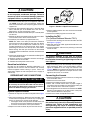
System Depressurization
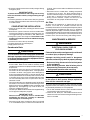
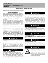
1. Remove the cap from the end of the liquid line. See Figure
1.
2. Verify pressurization by depressing the Schrader valve
on the end of the liquid line. Listen for any escaping gas.
If there is no pressure, test the coil for leakage.
• If leakage is found, clearly mark the location of the leak
and return the coil to the distributor for processing.
• If no leaks are found, the coil may be installed.
3. Depress the valve to relieve all pressure from the coil.
4. Remove and discard the valve core and valve core holder
on the liquid line.
5. Remove the rubber plug from the suction line.
Installing the TXV
(For Optional Bulkhead Mounted TXV’s)
1. Install the TXV retaining nut onto the inlet end of the TXV.
See Figure 3 (page 6).
2. Add small amount of HVAC approved thread lock to the
inlet end of the TXV.
3. Install the liquid line and accessory retaining nut onto the
end of the TXV.
CAUTION:
To prevent damage to the unit or internal
components, it is recommended that two wrenches
be used when loosening or tightening nuts. Do not
over tighten!
4. Align the retaining nut on the TXV body and hand tighten
both components. Mark a line on both bodies and then
tighten an additional ¼ turn using two wrenches. See
Figure 3. NOTE: The movement of the two lines will show
how much the nut is tightened. If a torque wrench is used,
tighten to 10-12 ft lbs or 14-16 Nm.
Connecting the Linesets
1. Remove the grommet from the suction line, making note
of its orientation and fit.
2. Remove the coil access door.
3. Remove the rubber plug from the suction line.
4. Route and cut both lineset tubes to proper length in
accordance with the outdoor unit specifications. Verify the
ends are round, clean, and free of any burrs.
5. Place the grommet on the suction line of the lineset. NOTE:
DO NOT install grommet in the door cutout at this point.
Allow sufficient distance to braze joint.
6. Connect the suction and liquid lineset tubes.
CAUTION:
It is recommended that a wet rag be wrapped around
the suction line in front of the close off plate before
applying heat. Failure to keep components cool
during brazing may result in structural damage,
premature equipment failure, or possible personal
injury.
Suction
Line
Liquid
Line
Cap
Cap
Schrader
Valve
Figure 1. Suction & Liquid Line Locations

5
for leaks. Consult local codes for additional restrictions or
precautions.
• Route the lines to a suitable drain, avoiding sharp bends
and pinching of the lines. The drain should maintain a
minimum horizontal slope in the direction of discharge of
no less than 1” vertical for every 10 ft of horizontal run.
• During system checkout, inspect the drain line and
connections to verify proper condensate drainage.
Air Filter
Air filters are not supplied as an integral part of this coil;
however, an air filter kit is available. The filter must be
installed upstream of the coil and inspected frequently. When
the filter becomes clogged with dust or lint, it should be
replaced (disposable type) or cleaned (washable type). It is
recommended that filters be inspected and replaced at least
twice during the year. Generally it is best to replace or clean
the filters at the start of each heating and cooling season.
MAINTENANCE & SERVICE
WARNING:
ELECTRICAL SHOCK, FIRE OR
EXPLOSION HAZARD
Failure to follow safety warnings exactly could result
in serious injury or property damage.
Improper servicing could result in dangerous
operation, serious injury, death or property damage.
• Before servicing, disconnect all electrical power
to the equipment.
• When servicing controls, label all wires prior to
disconnecting. Reconnect wires correctly.
• Verify proper operation after servicing.
CAUTION:
Do not operate the system without a suitable filter
in the return air duct system. Always replace the
filter with the same size and type.
To ensure optimum performance and to minimize possible
equipment failure, the following maintenance tasks should
be performed periodically on this equipment:
1. The air filter installed with the system should be checked
and cleaned or replaced twice per year.
2. Check the coil, drain pan, and condensate drain line for
cleanliness at the start of each heating and cooling season.
Clean as needed.
7. Braze the individual connections with dry nitrogen flowing
through the joints.
IMPORTANT NOTE:
To prevent internal oxidation and scaling from occuring,
braze all connections with dry nitrogen flowing through
the joints.
8. Install the grommet in the door cutout. Verify the grommet
is evenly aligned around the tube and securely positioned
in the door cutout.
COMPLETING THE INSTALLATION
1. Check the system for leaks, including the lineset and the
brazed joints.
2. Evacuate the system of moisture and non-condensables
to prevent low efficiency operation or damage to the unit.
The suggested range of evacuation is 350 - 500 microns.
3. Charge the system with refrigerant. Please Refer to the
outdoor unit installation manual for additional charging
instructions.
4. Install the coil access door (if removed).
5. Properly dispose of all removed parts.
6. Apply power to the unit.
Condensate Drain
CAUTION:
The coil must be level to ensure proper condensate
drainage. Improper condensate disposal may result
in structural damage, premature equipment failure,
or possible personal injury.
• Methods for disposing of condensate vary according
to local codes. Refer to local codes or authority having
jurisidiction for restrictions and proper condensate disposal
requirements.
• All condensate pans have primary and secondary drain
connections to meet FHA requirements. If the application
is located in or above a living space where damage may
result from condensate overflow, a separate 3/4 inch drain
must be provided from the secondary drain connection and
a secondary drain pan must be installed under the entire
unit. Run secondary drain lines to a place where they are
noticeable if used.
• The coil condensate pan is designed with 3/4” NPSC drain
connections. Use a PVC or similar material fitting to attach
the drain line to the pan. NOTE: The fitting should be hand
tightened only. Overtightening may crack the drain pan
and cause condensate to leak.
• The drain pan MUST be drained with field supplied tubing
or PVC pipe and adequately trapped.
IMPORTANT NOTE
Failure to install a trap may result in condensation
overflowing the drain pan, resulting in substantial
water damage to surrounding area.
• Prime the trap with water. Insulate the drain if it is located
in an unconditioned space, and test the condensate line

6
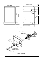
Figure 2. Coil Dimensions
W
HS
HL
H
5/8
4
17 3/4
20 3/4
FRONT VIEW
TOP VIEW
Distributor
Thermal Expansion
Valve (TXV)
Door
TXV
Retaining
Nut
Liquid Line
Stub w/ Screen
Accessory
Retaining Nut
Grommet
Figure 3. TXV Assembly

7
Table 1. C6 Upflow Coil Specifications
C6 CASED COIL SPECIFICATIONS
Model: C6BA
(1)(2)
T24-A
X24-A
T30-A
X30-A
X35-A
T24-B
X24-B
X26-B
T30-B
X30-B
X35-B
T36-B
X36-B
T42-B
X42-B
T36-C
X36-C
T42-C
X42-C
T48-C
X48-C
T60-C
X60-C
T42-D
X42-D
T48-D
X48-D
T60-D
X60-D
Nominal Capacity BTUH
(3)
24,000 30,000 36,000 24,000 24,000 30,000 36,000 36,000 42,000 36,000 42,000 48,000 60,000 42,000 48,000 60,000
Metering Device TXV TXV TXV TXV TXV TXV TXV TXV TXV TXV TXV TXV TXV TXV TXV TXV
Nominal Airflow (CFM) 800 1,000 1,000 800 1,200 1,000 1,200 1,200 1,400 1,200 1,400 1,600 2,000 1,400 1,600 2,000
W - Width (in.) 14 1/2 14 1/2 14 1/2 17 1/2 17 1/2 17 1/2 17 1/2 17 1/2 17 1/2 21 21 21 21 24 1/2 24 1/2 24 1/2
H - Height (in.) 20 3/4 20 3/4 20 3/4 20 3/4 26 3/4 20 3/4 20 3/4 26 3/4 26 3/4 26 3/4 26 3/4 30 1/4 30 1/4 30 1/4 30 1/4 30 1/4
HL - Height of Liquid Line (in.) 17 1/2 17 1/2 17 1/2 17 1/2 23 1/2 17 1/2 17 1/2 23 1/2 23 1/2 23 1/2 23 1/2 27 27 27 27 27
HS - Height of Suction Line (in.) 15 1/2 15 1/2 15 1/2 15 1/2 21 1/2 15 1/2 15 1/2 21 1/2 21 1/2 21 1/2 21 1/2 25 25 25 25 25
Connection - Liquid Line 3/8 3/8 3/8 3/8 3/8 3/8 3/8 3/8 3/8 3/8 3/8 3/8 3/8 3/8 3/8 3/8
Connection - Suction Line 3/4 3/4 3/4 3/4 3/4 3/4 3/4 3/4 3/4 7/8 7/8 7/8 7/8 7/8 7/8 7/8
Horizontal Drain Kit (4) 920265 920265 920265 920265 920266 920265 920265 920266 920266 920266 920266 920267 920267 920267 920267 920267
Table 1
C6 HORIZONTAL CASED COIL SPECIFICATIONS
Model: C6BH
(1)(2)
T24-A
X24-A
T30-A
X30-A
X35-A
T24-B
X24-B
X26-B
T30-B
X30-B
X35-B
T36-B
X36-B
T42-B
X42-B
T36-C
X36-C
T42-C
X42-C
T48-C
X48-C
T60-C
X60-C
T42-D
X42-D
T48-D
X48-D
T60-D
X60-D
Nominal Capacity BTUH
(3)
24,000 30,000 36,000 24,000 24,000 30,000 36,000 36,000 42,000 36,000 42,000 48,000 60,000 42,000 48,000 60,000
Metering Device TXV TXV TXV TXV TXV TXV TXV TXV TXV TXV TXV TXV TXV TXV TXV TXV
Nominal Airflow (CFM) 800 1,000 1,000 800 1,200 1,000 1,200 1,200 1,400 1,200 1,400 1,600 2,000 1,400 1,600 2,000
W - Width (in.) 14 1/4 14 1/4 14 1/4 17 1/2 17 1/2 17 1/2 17 1/2 17 1/2 17 1/2 21 21 21 21 24 1/2 24 1/2 24 1/2
H - Height (in.) 26 3/4 26 3/4 26 3/4 26 3/4 20 3/4 26 3/4 26 3/4 26 3/4 26 3/4 26 3/4 26 3/4 30 1/4 30 1/4 30 1/4 30 1/4 30 1/4
HL - Height of Liquid Line (in.) 23 1/2 23 1/2 23 1/2 23 1/2 17 1/2 23 1/2 23 1/2 23 1/2 23 1/2 23 1/2 23 1/2 27 27 27 27 27
HS - Height of Suction Line (in.) 21 1/2 21 1/2 21 1/2 21 1/2 15 1/2 21 1/2 21 1/2 21 1/2 21 1/2 21 1/2 21 1/2 25 25 25 25 25
Connection - Liquid Line 3/8 3/8 3/8 3/8 3/8 3/8 3/8 3/8 3/8 3/8 3/8 3/8 3/8 3/8 3/8 3/8
Connection - Suction Line
3/4 3/4 3/4 3/4 3/4 3/4 3/4 3/4 3/4 7/8 7/8 7/8 7/8 7/8 7/8 7/8
(1) Refer to sales specification sheets for Listed/Certified combinations of equipment and required accessories.
(2) X in the model description designates factory installed TXV for R-410a refrigerant.
T in the model description designates factory installed TXV for R-22 refrigerant.
(3) Refer to the current ARI Directory for certified ratings of split systems.
(4) Not required for "H" horizontal ready coils.
Table 2. C6 Horizontal Coil Specifications
Table 2

708823G (Replaces 708823F)
Specifications & illustrations subject to change without notice or incurring obligations (05/18).
O’Fallon, MO, © Nortek Global HVAC LLC 2018. All Rights Reserved.
-
 1
1
-
 2
2
-
 3
3
-
 4
4
-
 5
5
-
 6
6
-
 7
7
-
 8
8


Frigidaire C6B(A,H)-T Installation guide
- Type
- Installation guide
- This manual is also suitable for
Ask a question and I''ll find the answer in the document
Finding information in a document is now easier with AI
Related papers
-
Broan C6B(A,H)-T Installation guide
-
Broan C6B(A,H)-T Installation guide
-
Broan C3, C4, C5 Replacement Coils for MH Installation guide
-
-
Broan C6B(A,H)-F Installation guide
-
-
Broan 669470R Installation guide
-
-
Broan C5B(A,H) Installation guide
-
Broan C6B(A,H)-T Installation guide
Other documents
-
 General Filter 4551 Operating instructions
-
Intertherm B6BX Installation guide
-
Broan C(3,5)QA Installation guide
-
 GEARVITA T42 Hard reset manual
-
Dettson A-Coil Installation guide
-
ACiQ 24-ACL Owner's manual
-
 APR SUPPLY EVM4X Cased Cooling Only Evaporator Coil Multipoise User manual
-
Carrier CSPVA Installation guide
-
Carrier CSPHP6012ALA Installation guide
-
Panasonic CSHE36YAC6 Owner's manual


