6
TO ENSURE SAFETY
• Do not use the disc brake rotor if it is cracked or deformed. The disc brake rotor may
break, and result in serious injury due to a fall. Replace the disc brake rotor with a new
one.
• Do not use the disc brake rotor if its thickness is 1.5 mm or less. Also do not use it if the
aluminum surface becomes visible. The disc brake rotor may break, and result in serious
injury due to a fall. Replace the disc brake rotor with a new one.
• Do not continuously apply the brakes. Doing so may cause a sudden increase in the brake
lever stroke, preventing the brakes from operating and resulting in serious injury.
• Do not use the brakes with fluid leaking. Doing so may prevent the brakes from
operating and result in serious injury.
• Do not apply the front brake too strongly. If you do so, the front wheel may lock and the
bicycle may fall forward, and serious injury may result.
• Because the required braking distance will be longer during wet weather, reduce your
speed and apply the brakes early and gently. You may fall or collide and be seriously
injured.
• A wet road surface may cause tires to lose traction; therefore, to avoid this, reduce your
speed and apply the brakes early and gently. If the tires lose traction, you may fall and be
seriously injured.
• If the quick release lever is on the same side as the disc brake rotor, confirm that it does
not interfere with the disc brake rotor. Otherwise, the bicycle may fall forward, and
serious injury may result.
For installation to the bicycle, and maintenance:
• Do not use oil other than SHIMANO genuine mineral oil. Doing so may prevent the
brakes from operating and result in serious injury.
• Be sure to use only oil from a freshly-opened container. Doing so may prevent the brakes
from operating and result in serious injury.
• Do not let water or air bubbles get into the brake system. Doing so may prevent the
brakes from operating and result in serious injury.
• Do not use with a tandem bicycle. Doing so may prevent the brakes from operating and
result in serious injury due to a fall or collision.
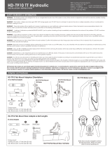
• When installing the brake caliper using screw
fixing pins, be sure to use mounting screws of
the appropriate length.
If not, the screw fixing pins may not be securely
fastened, and the screws may fall out.
Screw fixing pin