Page is loading ...

Statim 2000 & 5000
Rev. 7 PCB
Field
Training Manual

2
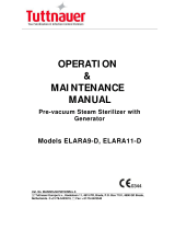
Statim Rev. 7 PCB User Setup
User setup mode – To initially setup your Statim
Hold down the Stop button and turn the unit ON.
Unit ID Setup *
Water Quality
Last Printout *
RS232 *
End Of Line CR/LF *
Serial Port Bit rate *
Printer user º char *
Save and Exit
Exit
* Only used when Statim is connected to a Printer or Data Logger
Keypad:
Unwrapped Select next item in the menu
Wrapped Select previous item in the menu
Rubber and Plastics Enter the indicated sub menu selection
Stop Exit menu to normal mode of operation
Time/Date Setup Mode – Set the proper time and date
Keypad:
Unwrapped Increase current field (the flashing value on the display)
Wrapped Decrease current field (the flashing value on the display)
Rubber and Plastics Select next field
Stop Save & exit menu to normal mode of operation
18:00 07/09/2008
HH:MM MM/DD/YYYY
>Time/Date Setup
Language Setup

3
Language Setup – Display information in your desired language
Available Languages
N. A. English (North American English)
U. K. English (United Kingdom English)
Francais (French)
Deutsch (German)
Espanol (Spanish)
Italiano (Italian)
Dansk (Danish)
Portugues
Nederlands
Japanese
Svenska (Swedish)
Polski (Polish)
Magyar (Hungarian)
Cesky (Czech)
Norsk (Norwegian)
Islenska (Iceland)
Slovencina (Slovak)
Eesti (Estonian)
Japanese (Sterimaster)
Romana (Romanian)
Lietuviuk (Lithuanian)
Slovenian (Slovenia)
Keypad:
Unwrapped Select next language
Wrapped Select previous language
Rubber and Plastics If Repeater mode is ON, this key will scroll through all the available
display messages of the chosen language.
Stop Save & exit menu to normal mode of operation
Unit ID Setup – Associate unit with an ID number (Used with printer)
Keypad:
Unwrapped Decrease current field (the flashing value on the display)
Wrapped Increase current field (the flashing value on the display)
Rubber and Plastics Select next digit
Stop Save & exit menu to normal mode of operation
Unit # :
000
N. A. ENGLISH

4
Water Quality – Display detected water quality
Screen Representation
x.x Water conductivity in uS (micro-Siemens)
NNN Water conductivity in ADC (Analog to Digital converter) counts (0…255)
y.y Water quality in ppm (parts per million)
Keypad:
Rubber and Plastics Return to main menu
Stop Exit menu to normal mode of operation
Last Printout – Printer reprints last cycle and unit returns to normal mode of operation
(Used with printer)
RS232 – To select which serial device to attach (Used with printer)
Serial Printer
USB FLASH/MSD
Keypad:
Unwrapped Move to next option, second line shows the new value
Wrapped Move to previous option, second line shows the new value
Rubber and Plastics Save and return to main menu
Stop Exit menu to normal mode of operation without saving
>RS232
N/A
>Water Quality
CD= x.xuS/NNN/y.yppm

5
End of Line CR/LF – Configure the printout layout (Used with printer)
-
CR
This only needs to be set if a serial printer is attached to the serial port.
Available options:
- No line terminator is sent after each line. To be used with printer that accepts only 20
characters per line and automatically advances to next line. Should be used with the
STATprinter.
CR A <CR> is sent at the end of the line. To be used with printers that advance to
beginning of next line when a CR is received.
CR/LF A <CR><LF> is sent at the end of the line. To be used with printers that translate
advance to beginning of next line only when LF is received.
Keypad:
Unwrapped Select next option. Second line shows the new value
Wrapped Select previous option. Second line shows the new value
Rubber and Plastics Save & exit to main menu
Stop Exit and return to normal mode of operation
SciCan Suggested
External Printers
End Of Line
CR/LF
Serial Port Bit Rate
Printer user ° char
Epson
TM-U220D C31C515603)
CR/LF 9600 248 [0xF8]
Citizen
IDP-3110-40 RF 120B
CR 9600 N/A
Star Micro
SP212FD42-120
CR 9600 210 [0xd2]
Star Micro
SP216FD41-120
CR/LF 9600 210 [0xd2]
Star Micro
SP512MD42-R
CR/LF 9600 210 [0xd2]
>End Of Line CR/LF
CR/LF

6
Serial Port Bit Rate – Choose bit rate for device connected to the serial port (Used with printer)
19200
57600
115200
300
1200
2400
4800
If USB FLASH/MSD is selected as the RS232 device, a Serial Port Bit Rate selection of 9600 will be
required for the Data Logger to be operational.
Keypad:
Unwrapped Select next value
Wrapped Select previous value
Rubber and Plastics Save & Return to main menu
Stop Exit without saving and return to normal mode of operation
Printer user ° char – Setting to print a °C sign (Used with printer)
32 decimal value for selected char-default 32
20 hex value for the selected char-default 20
Keypad:
Unwrapped Increase value by one
Wrapped Increase value by ten
Rubber and Plastics Select and return to main menu
Stop Exit without saving and return to normal mode of operation
Save and Exit – Saving settings and return to normal mode of operation
Upon selection, current settings are saved and unit restarts in normal mode of operation
Exit – Exit menu without saving settings
Upon selection, current settings are discarded, not
saved and unit restarts in normal mode of operation
Serial Port Bit Rate
9600
Printer user ° char
32
[
0x20
]

7
Statim Rev. 7 PCB Service Setup
Service setup mode – To enter the Service Setup Mode, turn power switch ON while holding
down Unwrapped and Wrapped buttons.
The Service Setup Mode is password protected, a password must be entered to continue. The default
password is, Unwrapped, Wrapped, Rubber and Plastics, Stop buttons pressed in this order. If the
password has been changed the backdoor password is, Unwrapped, Wrapped, Unwrapped, Wrapped
buttons pressed in this order.
Language Setup
Unit ID Setup *
Set cycle counter
Conductivity Setup
Water Cnd Tmp. Comp
Last Printout *
Stored CF Printouts *
Clear CF Printouts *
Display last CF#
Devices Test On/Off
Temperature Offset
Validation Offset
Voltage Calibration
Voltage setup
Repeater mode
RS232 *
End of Line CR/LF *
Serial Port Bitrate *
Printer user º char *
Factory default
Change Password
Backup NVRAM
Restore NVRAM
Save and Exit
Exit
Water Pump Type
Production Cycle
* Only used when Statim is connected to a Printer or Data Logger
Keypad:
Unwrapped Select next item in the menu
Wrapped Select previous item in the menu
Rubber and Plastics Enter the indicated sub menu selection
Stop Exit menu to normal mode of operation
Calibration – Select calibration to run validation thermocouple calibration cycle only.
Note: See page 19 for validation thermocouple calibration procedure.
>Calibration
Time/Date Setup

8
Time/Date Setup Mode – Set the proper time and date
Keypad:
Unwrapped Increase current field (the flashing value on the display)
Wrapped Decrease current field (the flashing value on the display)
Rubber and Plastics Select next field
Stop Save & exit menu to normal mode of operation
Language Setup – Display information in your desired language
Available Languages
N. A. English (North American English)
U. K. English (United Kingdom English)
Francais (French)
Deutsch (German)
Espanol (Spanish)
Italiano (Italian)
Dansk (Danish)
Portugues
Nederlands
Japanese
Svenska (Swedish)
Polski (Polish)
Magyar (Hungarian)
Cesky (Czech)
Norsk (Norwegian)
Islenska (Iceland)
Slovencina (Slovak)
Eesti (Estonian)
Japanese (Sterimaster)
Romana (Romanian)
Lietuviuk (Lithuanian)
Slovenian (Slovenia)
Keypad:
Unwrapped Select next language
Wrapped Select previous language
Rubber and Plastics If Repeater mode is ON, this key will scroll through all the available
display messages of the chosen language.
Stop Save & exit menu to normal mode of operation
18:00 07/09/2008
HH:MM MM/DD/YYYY
N. A. ENGLISH

9
Unit ID Setup – Associate unit with an ID number (Used with printer)
Keypad:
Unwrapped Decrease current field (the flashing value on the display)
Wrapped Increase current field (the flashing value on the display)
Rubber and Plastics Select next digit
Stop Save & exit menu to normal mode of operation
Set cycle counter – Adjust the recorded number of cycles ran
Keypad:
Unwrapped Decrease current digit
Wrapped Increase current digit
Rubber and Plastics Select next digit
Stop Save & exit menu to normal mode of operation
Conductivity Setup – To display detected water quality
If Statim has a Float Switch and Water Quality Sensor display below will appear.
Screen Representation
x.x Water conductivity in uS (micro-Siemens)
NNN Water conductivity in ADC (Analog to Digital converter) counts (0…255)
y.y Water quality in ppm (parts per million)
LL.L Lower value threshold (No water threshold) default 0.3uS
Values lower than this trigger “No water refill reservoir” error
FLOAT Indicates the reservoir has both a Float Switch & Water Quality Sensor
HH.H High value threshold (Bad water threshold) default 10uS
Values larger than this trigger “Bad water quality” error
G.GG Water conductivity circuit gain default 1.00
Note: Distilled water readings should be between Low and High thresholds.
Go to Water Conductivity Circuit Calibration to adjust readings.
Keypad:
Unwrapped Increase current field
Wrapped Decrease current field
Rubber and Plastics Move to next field
Stop Exit menu to normal mode of operation
Note: To perform Water Conductivity Circuit Calibration see page 18.
Unit # :
000
CD= x.xuS/NNN/y.yppm
L=LL.L H=HH.H G=G.GG
Cycle Number
000000
CD= x.xuS/NNN/y.yppm
FLOAT H=HH.H G=G.GG

10
Water Cnd Tmp Comp - To enable or disable water conductivity temperature compensation
Off
Keypad:
Unwrapped Select next option Second line shows the new value
Wrapped Select previous option. Second line shows the new value
Rubber and Plastics Select and return to main menu
Stop Exit, without saving, to normal mode of operation
Last Printout – Printer reprints last cycle and unit returns to normal mode of operation
(Used with printer)
Stored CF Printouts – Printer prints saved cycle fault printouts and unit returns to normal mode of
operation.
The saved CF printouts are sent to the printer or data logger only when either one is attached and
configured. The following types of errors are saved:
CF’s
Water quality or Water level low errors
Cycle interrupted due to errors (##)
Clear CF Printouts – Reset Cycle Fault printout list (Used with printer)
Yes
Keypad:
Unwrapped Select next option Second line shows the new value
Wrapped Select previous option. Second line shows the new value
Rubber and Plastics Select and return to main menu
Stop Exit, without saving, to normal mode of operation
Display last CF#
- Show the last Cycle Fault that occurred
Screen Representation
## Value of last recorded CF
(######) Cycle counter for last CF
Keypad:
Rubber and Plastics Return to main menu
Stop Exit to normal mode of operation
>Water Cnd Tmp Comp
On
>Clear CF Printouts
No
>Display last CF#
## (######)

11
Devices Test On/Off – Toggle the unit’s devices on or off
Valve Off
Compressor Off
Yellow LED Off
Extra 1L Off
Extra 2L Off
Drawer Relay Off
Keypad:
Unwrapped Select next option. Second line shows the new value
Wrapped Select previous option. Second line shows the new value
Rubber and Plastics Toggle On/Off selected device
Stop Return to main menu
Chamber Temperature Offset – View the offset of the chamber thermocouple
Screen Representation
## Offset value
Keypad:
Rubber and Plastics Return to main menu
Stop Exit to normal mode of operation
Validation Offset – View the offset of the validation thermocouple
Screen Representation
## Offset value
Keypad:
Rubber and Plastics Return to main menu
Stop Exit to normal mode of operation
>Devices Test On/Off
Pump Off
>Temperature Offset
##
>Validation Offset
##

12
Voltage Calibration – Adjust voltage offsets (not used for Statim 2000 & 5000)
Screen Representation
VVV Voltage measured by unit
CCC Voltage calibration offset. This should be adjusted so that the VVV value
is the same as the line voltage measured by the voltmeter.
Keypad:
Unwrapped Increase current field
Wrapped Decrease current field
Rubber and Plastics Select and return to main menu
Stop Exit, without saving, to normal mode of operation
Voltage Setup – Select input voltage of unit (not used for Statim 2000 & 5000)
230V
Keypad:
Unwrapped Select next option. Second line shows new value
Wrapped Select previous option. Second line shows new value
Rubber and Plastics Select and return to main menu
Stop Exit, without saving, to normal mode of operation
Repeater mode – Enable or disable unit to run cycles continuously
Off
Note: Repeater Mode must be turned OFF when testing is complete
Keypad:
Unwrapped Select next option. Second line shows new value
Wrapped Select previous option. Second line shows new value
Rubber and Plastics Select and return to main menu
Stop Exit, without saving, to normal mode of operation
>Voltage Calibration
V = VVV VCal = CCC
>Voltage Setup
115V
>Repeater mode
On

13
RS232 – To select which serial device to attach (Used with printer)
Serial Printer
USB FLASH/MSD
Keypad:
Unwrapped Move to next option, second line shows the new value
Wrapped Move to previous option, second line shows the new value
Rubber and Plastics Save and return to main menu
Stop Exit menu to normal mode of operation without saving
End of Line CR/LF – Configure the printout layout (Used with printer)
-
CR
This only needs to be set if a serial printer is attached to the serial port.
Available options:
- No line terminator is sent after each line. To be used with printer that accepts only 20
characters per line and automatically advances to next line. Should be used with the
STATprinter.
CR A <CR> is sent at the end of the line. To be used with printers that advance to
beginning of next line when a CR is received.
CR/LF A <CR><LF> is sent at the end of the line. To be used with printers that translate
advance to beginning of next line only when LF is received.
Keypad:
Unwrapped Select next option. Second line shows the new value
Wrapped Select previous option. Second line shows the new value
Rubber and Plastics Save & exit to main menu
Stop Exit and return to normal mode of operation
SciCan Suggested
External Printers
End Of Line
CR/LF
Serial Port Bit
Rate
Printer user ° char
Epson
TM-U220D (C31C515603)
CR/LF 9600 248 [0xF8]
Citizen
IDP-3110-40 RF 120B
CR 9600 N/A
Star Micro
SP212FD42-120
CR 9600 210 [0xd2]
Star Micro
SP216FD41-120
CR/LF 9600 210 [0xd2]
Star Micro
SP512MD42-R
CR/LF 9600 210 [0xd2]
>RS232
N/A
>End Of Line CR/LF
CR/LF

14
Serial Port Bit Rate – Choose bit rate for device connected to the serial port (Used with printer)
19200
57600
115200
300
1200
2400
4800
If USB FLASH/MSD is selected as the RS232 device, a Serial Port Bit Rate selection of 9600 will be
required for the Data Logger to be operational.
Keypad:
Unwrapped Select next value
Wrapped Select previous value
Rubber and Plastics Save & return to main menu
Stop Exit, without saving, and return to normal mode of operation
Printer user ° char – Setting to print a °C sign (Used with printer)
dd decimal value for selected char-default 32
hh hex value for the selected char-default 20
Keypad:
Unwrapped Increase value by one
Wrapped Increase value by ten
Rubber and Plastics Select and return to main menu
Stop Exit, without saving, and return to normal mode of operation
Factory default – Reset to factory default settings
Yes, Reset NVRAM
This function resets the NVRAM to factory default settings. The chamber and voltage calibration
offsets and conductivity settings will be reset. The cycle counter will not be reset.
Keypad:
Unwrapped Select next option. Second line shows the new value
Wrapped Select previous option. Second line shows the new value
Rubber and Plastics Save and return to main menu
Stop Exit, without saving, and return to normal mode of operation
Serial Port Bit Rate
9600
Printer user ° char
dd
[
0xhh
]
>Factory default
No

15
Change Password – Change the password required to access the service menu
The unit will query for a 4 key password
The unit will require that the user re-enter the same 4 key password
The unit will confirm that the password has been changed or if changing the
password failed, the unit will again query for a new 4 key password
In case the changed password is lost a backdoor password can be used: Unwrapped, Wrapped,
Unwrapped, Wrapped in this order.
Backup NVRAM – Saves a copy of the unit’s current settings
Yes
Keypad:
Unwrapped Select next option Second line shows the new value
Wrapped Select previous option. Second line shows the new value
Rubber and Plastics Select and return to main menu
Stop Exit, without saving, to normal mode of operation
Restore NVRAM – Restores the previously saved unit settings into the NVRAM
Yes
Keypad:
Unwrapped Select next option Second line shows the new value
Wrapped Select previous option. Second line shows the new value
Rubber and Plastics Select and return to main menu
Stop Exit, without saving, to normal mode of operation
Type New Password
****
Type New Password
****
Password Changed
>Backup NVRAM
No
>Restore NVRAM
No

16
Save and Exit – Saving settings and return to normal mode of operation
Upon selection, current settings are saved and unit restarts in normal mode of operation
Exit – Exit menu without saving settings
Upon selection, current settings are discarded, not saved and unit restarts in normal mode of operation
Water Pump Type – Used to select which manufacture’s Water Pump is installed in unit
All USA models use Ulka Pump at this time
Ulka
Production Cycle – For manufacturing use only
>Water Pump Type
Invensys

17
Statim Rev. 7 PCB Revision 600 Software
Low Threshold Water Conductivity Setup
To correct Refill Reservoir/Empty Waste Bottle message
1. Turn power switch ON while holding down Unwrapped and Wrapped buttons to enter
Service Mode.
2. The Service Mode is password protected, enter password to continue, default password is:
Unwrapped, Wrapped, Rubber and Plastics and Stop buttons pressed in this order.
Keypad function at this time:
Unwrapped Key: Select next item in the menu
Wrapped Key: Select previous item in the menu
Rubber and Plastics Key: Enter current selection
3. Press the Unwrapped Key until Conductivity Setup appears on the top line of the display,
then press the Rubber and Plastics Key.
4. Display should be similar to the example below.
Screen Representation
xx.x Water conductivity in uS
NNN Conductivity measurement in ADC (Analog to Digital) counts (0…255)
y.y Water conductivity in ppm (parts per million).
LL.L Lower value threshold in uS (No water threshold), default 0.3uS.
HH.H High valve threshold (Bad water threshold), default 10uS.
Values larger than this trigger “Water Quality is Not Acceptable” error.
G.GG Water conductivity circuit gain
Note: Distilled water readings should be between low and high thresholds.
Keypad functions in Conductivity Setup screen:
Unwrapped Key: Increase current field (the flashing value on the display)
Wrapped Key: Decrease current field (the flashing value on the display)
Rubber and Plastics Key: Move to next field
Stop Key: Exit
5. Adjust the low threshold value to the 0.1 uS.
6. A cursor will be flashing in the lower left corner of the display on the LL.L value.
7. Press the Wrapped Key to lower the value to 0.1 uS.
8. Press the Rubber and Plastics Key to accept the setting.
9. Press the Wrapped Key until Save and Exit appears on the top line of the display.
10. Display should be similar to the example below.
11. Press the Rubber and Plastics Key.
12. Drain the Water Reservoir and verify that the Statim says “Refill Reservoir/Empty
Waste Bottle” when the water level in the Water Reservoir is below the Water Quality
Sensor.
CD=xx.xuS/NNN/y.yppm
L=LL.L H=HH.H G=G.GG
>Save and Exit
Exit

18
Statim Rev. 7 PCB Water Conductivity Circuit Calibration
1. Disconnect conductivity sensor wires (J4-3 & J4-4).
2. Using a wire, short together the float pins (J4-5 & J4-6).
3. Turn power switch ON while holding down Unwrapped and Wrapped buttons to enter Service
Mode.
4. The Service Mode is password protected, enter password to continue, default password is:
Unwrapped, Wrapped, Rubber and Plastics and Stop buttons pressed in this order. If password
has been changed backdoor password is: Unwrapped, Wrapped, Unwrapped and Wrapped
buttons pressed in this order.
Keypad function at this time:
Unwrapped Key: Select next item in the menu
Wrapped Key: Select previous item in the menu
Rubber and Plastics Key: Enter current selection
5. Toggle through the menu selections using the keypad to reach Conductivity Setup and press
the Rubber and Plastics key.
6. Display should be similar to one of the examples below.
Screen Representation
xx.x Water conductivity in uS.
NNN Conductivity measurement in ADC (Analog to Digital) counts (0…255)
y.y Water conductivity in ppm (parts per million).
LL.L Lower value threshold in uS (No water threshold), default 0.3uS
FLOAT Indicates reservoir has both a Float & Water Quality Sensor
HH.H High valve threshold (Bad water threshold), default 10uS
Values larger than this trigger “Water Quality is Not Acceptable) error.
G.GG Water conductivity circuit gain, default 1.00
Note: Distilled water readings should be between low and high thresholds.
7. Check/adjust low and high threshold values to the default ones.
8. By pressing the Rubber and Plastics Key the selection moves between LO, HI and G.
9. Select “G” Water conductivity circuit gain (flashing value on the display), by pressing the
Rubber and Plastics Key.
10. Adjust G.GG value so the conductivity in ADC counts (NNN) shows 186±1 count.
11. Press Stop Key to exit the Water conductivity mode and save displayed thresholds “HH.H”,
“LL.L” and “G.GG” and enter normal mode of operation, “Select a Cycle” screen.
Keypad functions in Conductivity Setup screen:
Unwrapped Key: Increase current field (the flashing value on the display)
Wrapped Key: Decrease current field (the flashing value on the display)
Rubber and Plastics Key: Move to next field.
CD=xx.xuS/NNN/y.yppm
L=LL.L H=HH.H G=G.GG
CD=xx.xuS/NNN/y.yppm
FLOAT H=HH.H G=G.GG

19
Statim Rev. 7 PCB Validation Thermocouple Calibration
1. Turn power switch ON while holding down Unwrapped and Wrapped keys to enter Service
Mode.
2. The Service Mode is password protected, enter password to continue, default password is:
Unwrapped, Wrapped, Rubber and Plastics and Stop keys pressed in this order.
Keypad function at this time:
Unwrapped Key: Select next item in the menu
Wrapped Key: Select previous item in the menu
Rubber and Plastics Key: Enter current selection
3. Toggle through the menu selections using the keypad to reach Calibration and press the
Rubber and Plastics key.
4. Display should be similar to the example below.
Screen Representation
25.5 Validation thermocouple reading
FE Validation thermocouple hexadecimal offset compared with chamber reading
24.1 Chamber temperature in °C
F9 Chamber thermocouple hexadecimal offset
1.4 Difference between validation thermocouple and chamber thermocouple in °C
5. Start a Validation thermocouple self-calibration cycle. Press and hold the Unwrapped key and
at the same time press the Start key. The Validation thermocouple hexadecimal offset will
change to 00 and the character “*” will appear after the 00. The display should be similar to the
example below. The 00* on the display indicates the Validation thermocouple calibration cycle
is running. Note: If there is no cassette in the unit, the water quality is unacceptable or the
water level is low the Validation thermocouple calibration cycle will not run
6. Allow the Validation thermocouple self-calibration to complete. The temperature within the
chamber will rise to sterilization temperature. Wait until the sterilization phase of the
calibration cycle ends automatically. The 00* value will change to a new offset value. The unit
will vent automatically. After the unit has vented press the Stop key to end the calibration
cycle. Note: Backup NVRAM after calibration is complete.
25.5 FE 24.1 F9
1.4
25.5 00* 24.1 F9
1.4
/