Airwell HAF 12 User manual

Category
Split-system air conditioners
Type
User manual

This manual is also suitable for

HAF Series
Indoor Units Outdoor Units
HAF 7
CON 7 (Alpha)
GCN 7
HAF 9
GCN 9 (Alpha)
ONG3-9
HAF 12
GCN 12 (Alpha)
ONG3-12
Service Manual
SM HAFRPM 1-A.3 GB
MAY – 2009
REFRIGERANT
R410A
HEAT PUMP
COOLING ONLY
CONTENTS
A
LIST OF EFFECTIVE PAGES
SM HAFRPM 1-A.3 GB
LIST OF EFFECTIVE PAGES
Note: Changes in the pages are indicated by a “Revision#” in the footer of each effected page
(when none indicates no changes in the relevant page). All pages in the following list represent
effected/ non effected pages divided by chapters.
Dates of issue for original and changed pages are:
Original ....... 0 ........ February 2009
Total number of pages in this publication is 93 consisting of the following:
Page
No.
Revision
No. #
Page
No.
Revision
No. #
Page
No.
Revision
No. #
Title ....................... 1
A ........................... 1
i ............................. 1
1-1 - 1-3 ................ 2
2-1 - 2-3 ................ 2
3-1 ........................ 2
4-1 - 4-3 ................ 2
5-1 - 5-12 .............. 3
6-1 - 6-3 ................ 2
7-1 ........................ 2
8-1 - 8-3 ................ 2
9-1 ........................ 2
10-1-10-2 .............. 1
11-1 ....................... 1
12-1-12-32 ............ 2
13-1-13-2 .............. 1
14-1-14-23 ............ 2
Appendix -A ...........2
• Zero in this column indicates an original page.
*Due to constant improvements please note that the data on this service manual can be modified with out notice.
**Photos are not contractual
CONTENTS
i
TABLE OF CONTENTS
SM HAFRPM 1-A.3 GB
Table of Contents
1. INTRODUCTION ...................................................................................................1-1
2. PRODUCT DATA SHEET ......................................................................................2-1
3. RATING CONDITIONS ..........................................................................................3-1
4. OUTLINE DIMENSIONS .......................................................................................4-1
5. PERFORMANCE DATA & PRESSURE CURVES ................................................5-1
6. SOUND LEVEL CHARACTERISTICS ..................................................................6-1
7. ELECTRICAL DATA ..............................................................................................7-1
8. WIRING DIAGRAMS .............................................................................................8-1
9. ELECTRICAL CONNECTIONS .............................................................................9-1
10. REFRIGERATION DIAGRAMS .............................................................................10-1
11. TUBING CONNECTIONS ......................................................................................11-1
12. CONTROL SYSTEM .............................................................................................12-1
13. TROUBLESHOOTING ..........................................................................................13-1
14. EXPLODED VIEWS AND SPARE PARTS LISTS .................................................14-1
15. APPENDIX A .........................................................................................................15-1
1-1
INTRODUCTION
SM HAFRPM 1-A.3 GB
1. INTRODUCTION
1.1 General
The new HAF split wall mounted is based on the compact range. It comprise the ST
(cooling only) and RC (heat pump) models, as follows:
Cooling Only HAF 7 ST/CON 7 ST; HAF 7 ST/GCN 7 ST;
HAF 9 ST/GCN 9 ST; HAF 9 ST/ONG3-9 ST;
HAF 12 ST/GCN 12 ST; HAF 12 ST/ONG3-12 ST;
Heat Pump HAF 7 RC/CON 7 RC; HAF 7 RC/GCN 7 RC;
HAF 9 RC/GCN 9 RC; HAF 9 RC/ONG3-9 RC;
HAF 12 RC/GCN 12 RC; HAF 12 RC/ONG3-12 RC;
The indoor HAF units are available as LED display types, flat panel design, compact
dimensions, and low noise operation.
1.2 Main Features
The HAF series benefits from the most advanced technological innovations, namely:
R410A refrigerant
Micro processor control.
Advanced display on indoor unit with a backlighted display.
Infrared remote control with LED display.
Indoor large diameter cross flow fan, allowing low operation sound level.
Bended Indoor coil with treated aluminum fins and coating for improved efficiency.
Pre charged refrigerant up to the max allowing tubing distance.
Easy access to the interconnecting tubing and wiring connections.
Refrigerant pipes can be connected to the indoor unit from 5 different optional
directions.
Motorized flaps.
Self diagnostic LED lighting fo easy of maintenance.
Easy installation and service.
CONTENTS
1-2
INTRODUCTION
SM HAFRPM 1-A.3 GB
1.3 Indoor Unit
The indoor unit is wall mounted, and can be easily fitted to many types of residential
and commercials applications.
It includes:
Casing with air inlet and outlet grills.
A large-diameter tangential fan.
Bended coil with treated aluminum fins.
Motorized flaps.
3-speed motor with internal protection.
Advanced electronic control box assembly.
Interconnecting wiring terminal block.
Mounting plate.
1.4 Filtration
The HAF series presents several types of air filters:
Easily accessible, and re-usable pre-filters (mesh)
Nm photo cata + Bi anti bacteria.
1.5 Control
The microprocessor indoor controller, and an infrared remote control, supplied as
standard, provide complete operating function and programming. For further details
please refer to the Operation Manual, Appendix A.
1.6 Outdoor Unit
The HAF outdoor units can be installed as floor or wall mounted units by using a
wall supporting bracket. The metal sheets are protected by anti- corrosion paint work
allowing long life resistance. All outdoor units are pre-charged. For further information
please refer to the Product Data Sheet, Chapter 2.
It includes :
A Rotary compressor mounted in a soundproofed compartment.
Axial fan.
Outdoor coil with hydrophilic louver fins for RC units.
Outlet air fan grill.
Service valves” flare” type connection.
Interconnecting wiring terminal block.
CONTENTS
1-3
INTRODUCTION
SM HAFRPM 1-A.3 GB
1.7 Tubing Connections
Flare type interconnecting tubing can be produced on site.
A connection pipe kit is provided in outdoor package.
For further details please refer to the Installation Manual, Appendix A.
1.8 Inbox Documentation
Each unit is supplied with its own installation and operation manuals.
1.9 Matching Table
OUTDOOR UNITS
INDOOR UNITS
MODEL REFRIGER.
HAF 7 HAF 9 HAF 12
CON 7 / GCN7 R410A
GCN 9 / ONG3-9 R410A
GCN 12 / ONG3-12 R410A
CONTENTS
2-1
PRODUCT DATA SHEET
SM HAFRPM 1-A.3 GB
2. PRODUCT DATA SHEET
2.1 HAF 7 / CON 7
(1) Rating conditions in accordance with ISO 5151 and ISO 13253 (for ducted units) and EN 14511.
(2) Airflow in ducted units; at nominal external static pressure.
(3) Sound power in ducted units is measured at air discharge.
(4) Sound pressure level measured at 1 meter distance from unit.
8QLWV
%WXKU
N:
N:
::
9
3K
+]
$
:
:
$
$
+530
+PKU
0LQ 3D
+ G%$
+0/ G%$
OKU
PP
:[+[' PP
NJ
:[+[' PP
NJ
XQLWV
XQLWV
+530
+ PKU
+ G%$
+ G%$
:[+[' PP
NJ
:[+[' PP
NJ
8QLWV
XQLWV
NJP
,QPP
,QPP
P
P
N:
2WKHUV
2SHUDWLRQFRQWUROW\SH 5HPRWHFRQWURO
+HDWLQJHOHPHQWV2SWLRQ
&RQQHFWLRQV
EHWZHHQXQLWV
/LTXLGOLQH 
6XFWLRQOLQH 
0D[WXELQJOHQJWK 0D[
0D[KHLJKWGLIIHUHQFH 0D[
6WDQGDUGFKDUJH 
$GGLWLRQDOFKDUJH
Pİ/HQJWKİPJP˘/HQJWKİPJ
6WDFNLQJKHLJKW
5HIULJHUDQWW\SH 5$
3DFNDJHGZHLJKW ZLWKNLW
8QLWVSHUSDOOHW 
1
HW
:HLJKW

3DFNDJHGLPHQVLRQV [[
6RXQGSUHVVXUHOHYHO 
'LPHQVLRQV [[

$LUIORZ 
6RXQGSRZHUOHYHO 
6WDFNLQJKHLJKW
287'225
5HIULJHUDQWFRQWURO &DSLOODU\
&RPSUHVVRUW\SHPRGHO 5RWDU\726+,%$3$;&'='(
)DQW\SHTXDQWLW\ 3URSHOOHUGLUHFW[
)DQVSHHGV
3DFNDJHGZHLJKW 
8QLWVSHUSDOOHW 
1
HW
:HLJKW
3DFNDJHGLPHQVLRQV [[
&RQGHQVWDWHGUDLQWXEH,' 
'LPHQVLRQV [[

6RXQGSUHVVXUHOHYHO 
0RLVWXUHUHPRYDO 
,1'225
)DQW\SHTXDQWLW\ &URVVIORZ[
)DQVSHHGV 
$LUIORZ 
([WHUQDOVWDWLFSUHVVXUH
6RXQGSRZHUOHYHO
6WDUWLQJFXUUHQW 
&LUFXLWEUHDNHUUDWLQJ 
3UDWHG,'8 
3UDWHG,'82'8 
5DWHGFXUUHQW  
3RZHUIDFWRU  
(QHUJ\HIILFLHQF\FODVV % &
3RZHUVXSSO\


3RZHULQSXW  
((5&RROLQJRU&23+HDWLQJ  
&DSDFLW\
 
 
,QVWDOODWLRQ0HWKRGRI3LSH )ODUHG
&KDUDFWHULVWLFV &RROLQJ +HDWLQJ
0RGHO,QGRRU8QLW +$)
0RGHO2XWGRRU8QLW
&21
CONTENTS
2-2
PRODUCT DATA SHEET
SM HAFRPM 1-A.3 GB
2.2 HAF 9 / GCN 9
(1) Rating conditions in accordance with ISO 5151 and ISO 13253 (for ducted units). and EN 14511
(2) Airflow in ducted units; at nominal external static pressure.
(3) Sound power in ducted units is measured at air discharge.
(4) Sound pressure level measured at 1 meter distance from unit.
8QLWV
%WXKU
N:
N:
::
9
3K
+]
$
:
:
$
$
+0/ 530
+0/ PKU
0LQ 3D
+ G%$
+0/ G%$
OKU
PP
:[+[' PP
NJ
:[+[' PP
NJ
XQLWV
XQLWV
+530
+ PKU
+ G%$
+ G%$
:[+[' PP
NJ
:[+[' PP
NJ
8QLWV
XQLWV
NJP
,QPP
,QPP
P
P
N:
2WKHUV
2SHUDWLRQFRQWUROW\SH 5HPRWHFRQWURO
+HDWLQJHOHPHQWV2SWLRQ
&RQQHFWLRQV
EHWZHHQXQLWV
/LTXLGOLQH 
6XFWLRQOLQH 
0D[WXELQJOHQJWK 0D[
0D[KHLJKWGLIIHUHQFH 0D[
6WDQGDUGFKDUJH 
$GGLWLRQDOFKDUJH
Pİ/HQJWKİPJP˘/HQJWKİPJ
6WDFNLQJKHLJKW
5HIULJHUDQWW\SH 5$
3DFNDJHGZHLJKW ZLWKNLW
8QLWVSHUSDOOHW
1
HW
:HLJKW

3DFNDJHGLPHQVLRQV [[
6RXQGSUHVVXUHOHYHO 
'LPHQVLRQV [[

$LUIORZ 
6RXQGSRZHUOHYHO 
6WDFNLQJKHLJKW
287'225
5HIULJHUDQWFRQWURO &DSLOODU\
&RPSUHVVRUW\SHPRGHO 5RWDU\726+,%$3$;&)='(
)DQW\SHTXDQWLW\ 3URSHOOHUGLUHFW[
)DQVSHHGV
3DFNDJHGZHLJKW 
8QLWVSHUSDOOHW 
1
HW
:HLJKW
3DFNDJHGLPHQVLRQV [[
&RQGHQVWDWHGUDLQWXEH,' 
'LPHQVLRQV [[

6RXQGSUHVVXUHOHYHO 
0RLVWXUHUHPRYDO 
,1'225
)DQW\SHTXDQWLW\ &URVVIORZ[
)DQVSHHGV 
$LUIORZ 
([WHUQDOVWDWLFSUHVVXUH
6RXQGSRZHUOHYHO
6WDUWLQJFXUUHQW 
&LUFXLWEUHDNHUUDWLQJ 
3UDWHG,'8 
3UDWHG,'82'8 
5DWHGFXUUHQW  
3RZHUIDFWRU  
(QHUJ\HIILFLHQF\FODVV % &
3RZHUVXSSO\


3RZHULQSXW  
((5&RROLQJRU&23+HDWLQJ  
&DSDFLW\
 
 
,QVWDOODWLRQ0HWKRGRI3LSH )ODUHG
&KDUDFWHULVWLFV &RROLQJ +HDWLQJ
0RGHO,QGRRU8QLW +$)
0RGHO2XWGRRU8QLW *&1
CONTENTS
2-3
PRODUCT DATA SHEET
SM HAFRPM 1-A.3 GB
2.3 HAF 12 / GCN 12
(1) Rating conditions in accordance with ISO 5151 and ISO 13253 (for ducted units). and EN 14511
(2) Airflow in ducted units; at nominal external static pressure.
(3) Sound power in ducted units is measured at air discharge.
(4) Sound pressure level measured at 1 meter distance from unit.
8QLWV
%WXKU
N:
N:
::
9
3K
+]
$
:
:
$
$
+0/ 530
+0/ PKU
0LQ 3D
+ G%$
+0/ G%$
OKU
PP
:[+[' PP
NJ
:[+[' PP
NJ
XQLWV
XQLWV
+530
+PKU
+ G%$
+ G%$
:[+[' PP
NJ
:[+[' PP
NJ
8QLWV
XQLWV
NJP
,QPP
,QPP
P
P
N:
2WKHUV
2SHUDWLRQFRQWUROW\SH 5HPRWHFRQWURO
+HDWLQJHOHPHQWV2SWLRQ
&RQQHFWLRQV
EHWZHHQXQLWV
/LTXLGOLQH 
6XFWLRQOLQH 
0D[WXELQJOHQJWK 0D[
0D[KHLJKWGLIIHUHQFH 0D[
6WDQGDUGFKDUJH 
$GGLWLRQDOFKDUJH
Pİ/HQJWKİPJP˘/HQJWKİPJ
6WDFNLQJKHLJKW
5HIULJHUDQWW\SH 5$
3DFNDJHGZHLJKW ZLWKNLW
8QLWVSHUSDOOHW
1HW:HLJKW 
3DFNDJHGLPHQVLRQV [[
6RXQGSUHVVXUHOHYHO 
'LPHQVLRQV [[[

$LUIORZ 
6RXQGSRZHUOHYHO 
6WDFNLQJKHLJKW
287'225
5HIULJHUDQWFRQWURO &DSLOODU\
&RPSUHVVRUW\SHPRGHO 5RWDU\726+,%$3$;&)7
)DQW\SHTXDQWLW\ 3URSHOOHUGLUHFW[
)DQVSHHGV
3DFNDJHGZHLJKW 
8QLWVSHUSDOOHW 
1HW:HLJKW
3DFNDJHGLPHQVLRQV ;;
&RQGHQVWDWHGUDLQWXEH,' 
'LPHQVLRQV ;;

6RXQGSUHVVXUHOHYHO 
0RLVWXUHUHPRYDO 
,1'225
)DQW\SHTXDQWLW\ &URVVIORZ[
)DQVSHHGV 
$LUIORZ 
([WHUQDOVWDWLFSUHVVXUH
6RXQGSRZHUOHYHO
6WDUWLQJFXUUHQW 
&LUFXLWEUHDNHUUDWLQJ 
3UDWHG,'8

3UDWHG,'82'8

5DWHGFXUUHQW  
3RZHUIDFWRU
 
(QHUJ\HIILFLHQF\FODVV % &
3RZHUVXSSO\


3RZHULQSXW  
((5&RROLQJRU&23+HDWLQJ  
&DSDFLW\
 
 
,QVWDOODWLRQ0HWKRGRI3LSH )ODUHG
&KDUDFWHULVWLFV &RROLQJ +HDWLQJ
0RGHO,QGRRU8QLW +$)
0RGHO2XWGRRU8QLW *&1
CONTENTS
2-4
PRODUCT DATA SHEET
SM HAFRPM 1-A.3 GB
HAF7, 9, 12 Matching GCN7, ONG3-9, ONG3-12
Waiting For SII
CONTENTS
3-1
RATING CONDITIONS
SM HAFRPM 1-A.3 GB
3. RATING CONDITIONS
Standard conditions in accordance with ISO 5151, ISO 13253 (for ducted units)
and EN 14511.
Cooling:
Indoor: 27
o
C DB 19
o
C WB
Outdoor: 35
o
C DB
Heating:
Indoor: 20
o
C DB
Outdoor: 7
o
C DB 6
o
C WB
3.1 Operating Limits
3.1.1 R410A
Indoor Outdoor
Cooling
Upper limit
32
o
C DB 23
o
C WB 46
o
C DB
Lower limit 21
o
C DB 15
o
C WB 10
o
C DB
Heating
Upper limit 27
o
C DB 24
o
C DB 18
o
C WB
Lower limit 10
o
C DB -15
o
C DB -10
o
C WB
Voltage 198 – 264 V
CONTENTS
4-1
OUTLINE DIMENSIONS
SM HAFRPM 1-A.3 GB
4. OUTLINE DIMENSIONS
4.1 Indoor Unit: HAF 7, HAF 9
4.2
Indoor Unit: HAF 12
CONTENTS
4-2
OUTLINE DIMENSIONS
SM HAFRPM 1-A.3 GB
4.3 Outdoor Unit: CON 7
4.4 Outdoor Unit: GCN 7, GCN 9, GCN 12
AI R OUTL E T
AI R I NTAKE
CONTENTS
4-3
OUTLINE DIMENSIONS
SM HAFRPM 1-A.3 GB
4.5 Indoor Unit: ONG3-9, ONG3-12
CONTENTS
5-1
PERFORMANCE DATA & PRESSURE CURVES
SM HAFRPM 1-A.3 GB
5. PERFORMANCE DATA & PRESSURE CURVES
5.1 HAF 7 / CON 7
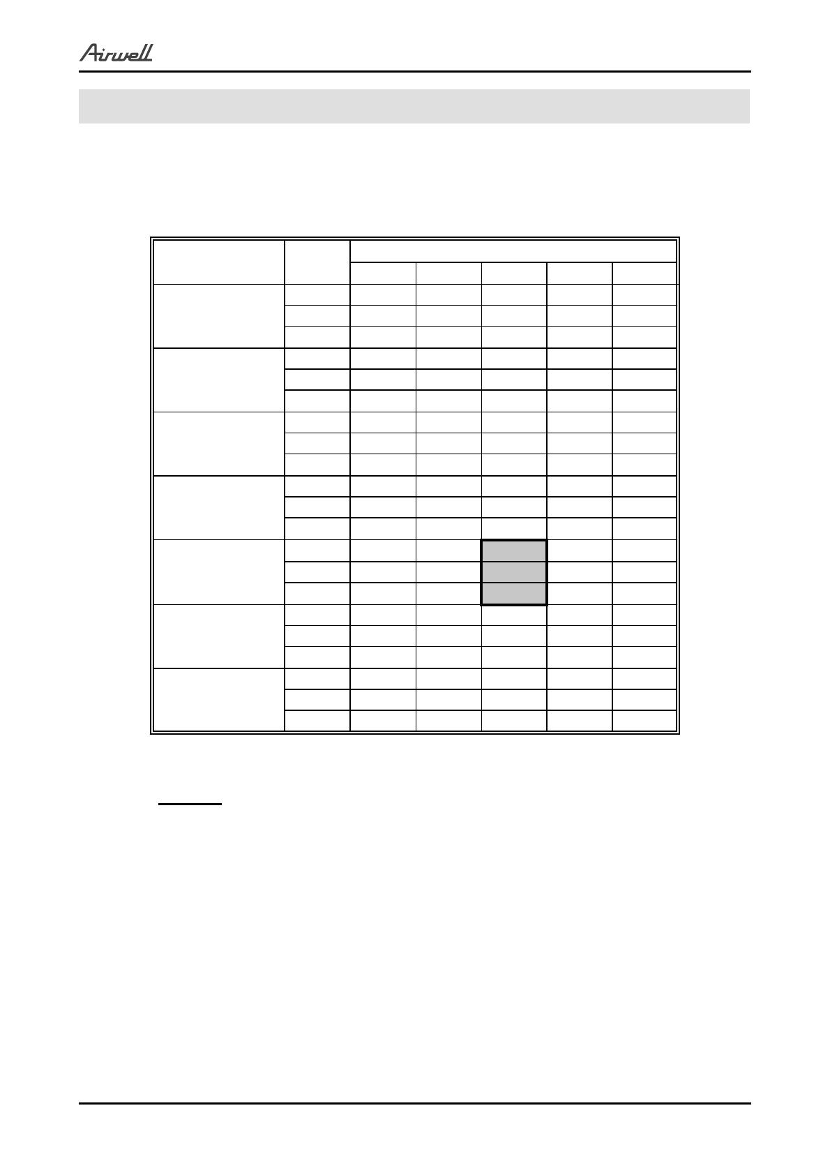
5.1.1 Cooling Mode at 7.5m Tubing Connection.
230V : Indoor Fan at High Speed.
ENTERING AIR
DB OD Coil(
o
C)
Data
ENTERING AIR WB/DB ID Coil(
o
C)
15/21 17/24 19/27 21/29 23/32
15
(1)
TC 2.12 2.19 2.25 2.30 2.33
SC 1.57 1.63 1.7 1.74 1.77
PI 0.49 0.49 0.49 0.49 0.49
20
(1)
TC 2.05 2.16 2.23 2.28 2.33
SC 1.54 1.62 1.69 1.74 1.77
PI 0.53 0.53 0.53 0.54 0.54
25
TC 1.94 2.09 2.20 2.27 2.32
SC 1.5 1.59 1.67 1.72 1.75
PI 0.57 0.58 0.58 0.59 0.59
30
TC 1.81 1.97 2.13 2.21 2.27
SC 1.45 1.54 1.64 1.69 1.72
PI 0.62 0.63
0.63
0.64 0.64
35
TC 1.68 1.82
2.01
2.11 2.21
SC 1.38 1.48 1.60 1.65 1.68
PI 0.67 0.68
0.69
0.7 0.70
40
TC 1.53 1.66
1.81
1.98 2.09
SC 1.30 1.40 1.51 1.56 1.59
PI 0.72 0.73 0.74 0.75 0.76
46
TC 1.32 1.45 1.59 1.76 1.90
SC 1.20 1.28 1.38 1.43 1.46
PI 0.79 0.80 0.82 0.83 0.84
LEGEND
TC Total Cooling Capacity, kW
SC Sensible Capacity, kW
PI Power Input, kW
WB Wet Bulb Temp., (
o
C)
DB Dry Bulb Temp., (
o
C)
ID Indoor
OD Outdoor
(1) Marked area is below standard operating limits. For operating in low ambient
conditions, an A.S.K Kit is required.
CONTENTS
5-2
PERFORMANCE DATA & PRESSURE CURVES
SM HAFRPM 1-A.3 GB
5.1.2 Heating
ENTERING WB
OD COIL(
o
C)
ENTERING AIR DB ID COIL(
O
c)
15 20 25
TH Pl TH Pl TH Pl
-10 1.08 0.51 1.04 0.55 0.99 0.57
-7 1.16 0.52 1.12 0.55 1.08 0.58
-2 1.23 0.53 1.19 0.56 1.15 0.60
2 1.50 0.56
1.44 0.59
1.37 0.63
6 2.11 0.60 2.05 0.64 1.98 0.68
10 2.30 0.63
2.23 0.68
2.17 0.72
15 2.48 0.66 2.42 0.71 2.36 0.76
20 2.61 0.68 2.55 0.74 2.48 0.79
LEGEND
TH Total Heating Capacity, kW
PI Power Input, kW
WB Wet Bulb Temp., (
o
C)
DB Dry Bulb Temp., (
o
C)
ID Indoor
OD Outdoor
CONTENTS
5-3
PERFORMANCE DATA & PRESSURE CURVES
SM HAFRPM 1-A.3 GB
5.2 Model: HAF 7 / GCN 7
5.2.1 Cooling
'LVFKDUJH3UHVVXUH962XWGRRU7HPS
















      
2XWGRRU7HPS'%
R
&
'LVFKDUJH3UHVVXUH%DU>J@
:%'%嘙&
:%'%嘙&
:%'%嘙&
:%'%嘙&
:%'%嘙&
6XFWLRQ3UHVVXUH962XWGRRU7HPS








      
2XWGRRU7HPS'%
R
&
6XFWLRQ3UHVVXUH%DU>J@
:%'%嘙&
:%'%嘙&
:%'%嘙&
:%'%嘙&
:%'%嘙&
CONTENTS
5-4
PERFORMANCE DATA & PRESSURE CURVES
SM HAFRPM 1-A.3 GB
5.2.2 Heating
'LVFKDUJH3UHVVXUH962XWGRRU7HPS











2XWGRRU7HPS:%
R
&
'LVFKDUJH3UHVVXUH%DU>J@
'%嘙&
'%嘙&
'%嘙&
6XFWLRQ3UHVVXUH962XWGRRU7HPS









    
2XWGRRU7HPS:%
R
&
6XFWLRQ3UHVVXUH%DU>J@
'%嘙&
'%嘙&
'%嘙&
CONTENTS
5-5
PERFORMANCE DATA & PRESSURE CURVES
SM HAFRPM 1-A.3 GB
5.3 HAF 9 / GCN 9
5.3.1 Cooling Mode at 7.5m Tubing Connection.
230V : Indoor Fan at High Speed.
ENTERING AIR
DB OD Coil(
o
C)
Data
ENTERING AIR WB/DB ID Coil(
o
C)
15/21 17/24 19/27 21/29 23/32
15
(1)
TC 2.69 2.78 2.85 2.92 2.96
SC 1.91 1.99 2.07 2.12 2.16
PI 0.60 0.60 0.61 0.61 0.61
20
(1)
TC 2.60 2.74 2.83 2.89 2.96
SC 1.87 1.97 2.06 2.11 2.15
PI 0.65 0.66 0.66 0.66 0.66
25
TC 2.46 2.66 2.79 2.88 2.95
SC 1.82 1.93 2.04 2.10 2.14
PI 0.71 0.71 0.72 0.72 0.73
30
TC 2.30 2.51 2.71 2.80 2.89
SC 1.77 1.88 2.00 2.05 2.09
PI 0.76 0.77
0.78
0.79 0.79
35
TC 2.13 2.31
2.55
2.68 2.80
SC 1.68 1.80 1.95 2.01 2.05
PI 0.82 0.84
0.85
0.86 0.86
40
TC 1.94 2.11
2.30
2.52 2.65
SC 1.58 1.70 1.84 1.90 1.94
PI 0.89 0.90 0.92 0.93 0.94
46
TC 1.68 1.84 2.02 2.23 2.41
SC 1.46 1.56 1.68 1.74 1.78
PI 0.97 0.98 1.01 1.02 1.03
LEGEND
TC Total Cooling Capacity, kW
SC Sensible Capacity, kW
PI Power Input, kW
WB Wet Bulb Temp., (
o
C)
DB Dry Bulb Temp., (
o
C)
ID Indoor
OD Outdoor
(1) Marked area is below standard operating limits. For operating in low ambient
conditions, an A.S.K Kit is required.
CONTENTS
5-6
PERFORMANCE DATA & PRESSURE CURVES
SM HAFRPM 1-A.3 GB
5.3.2 Heating
ENTERING WB
OD COIL(
o
C)
ENTERING AIR DB ID COIL(
O
c)
15 20 25
TH Pl TH Pl TH Pl
-10 1.45 0.70 1.39 0.75 1.34 0.79
-7 1.56 0.72 1.50 0.76 1.45 0.80
-2 1.66 0.73 1.60 0.77 1.55 0.82
2 2.01 0.77
1.93 0.81
1.85 0.86
6 2.84 0.82 2.76 0.88 2.66 0.93
10 3.09 0.87
3.01 0.93
2.93 0.99
15 3.34 0.91 3.26 0.98 3.17 1.04
20 3.52 0.93 3.44 1.01 3.34 1.09
LEGEND
TH Total Heating Capacity, kW
PI Power Input, kW
WB Wet Bulb Temp., (
o
C)
DB Dry Bulb Temp., (
o
C)
ID Indoor
OD Outdoor
CONTENTS
  • Page 1 1
  • Page 2 2
  • Page 3 3
  • Page 4 4
  • Page 5 5
  • Page 6 6
  • Page 7 7
  • Page 8 8
  • Page 9 9
  • Page 10 10
  • Page 11 11
  • Page 12 12
  • Page 13 13
  • Page 14 14
  • Page 15 15
  • Page 16 16
  • Page 17 17
  • Page 18 18
  • Page 19 19
  • Page 20 20
  • Page 21 21
  • Page 22 22
  • Page 23 23
  • Page 24 24
  • Page 25 25
  • Page 26 26
  • Page 27 27
  • Page 28 28
  • Page 29 29
  • Page 30 30
  • Page 31 31
  • Page 32 32
  • Page 33 33
  • Page 34 34
  • Page 35 35
  • Page 36 36
  • Page 37 37
  • Page 38 38
  • Page 39 39
  • Page 40 40
  • Page 41 41
  • Page 42 42
  • Page 43 43
  • Page 44 44
  • Page 45 45
  • Page 46 46
  • Page 47 47
  • Page 48 48
  • Page 49 49
  • Page 50 50
  • Page 51 51
  • Page 52 52
  • Page 53 53
  • Page 54 54
  • Page 55 55
  • Page 56 56
  • Page 57 57
  • Page 58 58
  • Page 59 59
  • Page 60 60
  • Page 61 61
  • Page 62 62
  • Page 63 63
  • Page 64 64
  • Page 65 65
  • Page 66 66
  • Page 67 67
  • Page 68 68
  • Page 69 69
  • Page 70 70
  • Page 71 71
  • Page 72 72
  • Page 73 73
  • Page 74 74
  • Page 75 75
  • Page 76 76
  • Page 77 77
  • Page 78 78
  • Page 79 79
  • Page 80 80
  • Page 81 81
  • Page 82 82
  • Page 83 83
  • Page 84 84
  • Page 85 85
  • Page 86 86
  • Page 87 87
  • Page 88 88
  • Page 89 89
  • Page 90 90
  • Page 91 91
  • Page 92 92
  • Page 93 93
  • Page 94 94
  • Page 95 95
  • Page 96 96
  • Page 97 97
  • Page 98 98
  • Page 99 99
  • Page 100 100
  • Page 101 101
  • Page 102 102

Airwell HAF 12 User manual

Category
Split-system air conditioners
Type
User manual
This manual is also suitable for

Ask a question and I''ll find the answer in the document

Finding information in a document is now easier with AI