Page is loading ...

GA9 Series
Reference # - TD080
Rev. - C
Date - 0411
2525 GARDNER ROAD, BROADVIEW, IL 60155
1.800.323.9114 • Outside U.S. 1.708.865.1500
www.tksimplex.com
- Note -
This Operational Manual is intended as a technical guideline only. SIMPLEX accepts no liability for any use or reliance made of any information
in this Operational Manual. All information, illustrations and specications in this Operational Manual are based on the latest information
available at the time of publication. SIMPLEX reserves the right to make changes at any time without notice. Equipment operators and installers
shall be responsible for ensuring that a safe working environment and safe systems of work are in place before operating the equipment.
©2011 SIMPLEX
IMPORTANT - READ CAREFULLY
This manual contains important information about the correct installation, operation and maintenance of this equipment. All persons involved
in the installation, operation and maintenance of this equipment must be thoroughly familiar with the contents of this manual. To safeguard
against the possibility of personal injury or property damage, follow the recommendations and instructions of this manual. Keep this manual for
reference.
WARRANTY STATEMENT
SIMPLEX products are warranted to be free of defects in materials and workmanship under normal use for as long as the original purchaser
owns them, subject to the guidelines and limitations listed. This warranty does not cover: normal wear & tear, cosmetic items, abuse,
overloading,alterations, improper lubrication, or use in a manner for which they are not intended. If the customer believes a product is defective,
the
product must be delivered, or shipped freight prepaid, to the nearest SIMPLEX Authorized Service Center for evaluation and repair.
RECEIVING INSTRUCTIONS
Important! Make sure to inspect all of the components for shipping damage. If damage is found, notify carrier at once. Shipping damage will
not be covered by warranty. The carrier is responsible for all loss associated with shipping damage.
CONTENTS
SECTION
Receiving Instructions ...............................................................................................................................................1.0
Safety ........................................................................................................................................................................2.0
Technical Specications ............................................................................................................................................3.0
Basic Operation and Function ...................................................................................................................................4.0
Basic Operation .........................................................................................................................................................4.1
After Completing the Job ...........................................................................................................................................4.2
Periodic Maintenance ................................................................................................................................................5.0
Maintain Oil Level ......................................................................................................................................................5.1
Troubleshooting .........................................................................................................................................................6.0

••• 2 •••
1.0 RECEIVING INSTRUCTIONS
Important! Make sure to inspect all of the components for shipping damage. If damage is found, notify carrier at once. Shipping damage will not
be covered by warranty. The carrier is responsible for all loss associated with shipping damage.
2.0 SAFETY
Make sure to read the instructions, warnings and precautions carefully. Follow all recommended safety precautions to avoid personal injury or
damage to the unit. Simplex cannot be responsible for any damage or injury from unsafe use, lack of maintenance, or incorrect operation. In the
event any questions or concerns arise, contact SIMPLEX or a local SIMPLEX Distributor for clarication.
The pump’s maximum working pressure is 10,000 PSI (700kg/cm2). Make sure that all hydraulic equipment such as rams, hoses, etc. used with
this pump are rated at 10,000 PSI (700kg/cm2) operating pressure.
If you have never been trained on high-pressure hydraulic safety, consult your distributor or service center for a free Simplex Hydraulic Safety
Course. Failure to comply with the following cautions and warnings could cause equipment damage, property damage, or personal injury.
DANGER: is only used when your action or lack of action may cause serious injury or even death.
WARNING: indicates a potential danger that requires correct procedures or practices to avoid personal injury.
CAUTION: is used to indicate correct operating or maintenance procedures and practices to prevent damage to, or destruction
of equipment, or other property.
WARNING: Wear proper personal protective gear when operating hydraulic equipment.
WARNING: The system operating pressure must not exceed the pressure rating of the lowest rated component in the system.
Install pressure gauges in the system to monitor operating pressure. Gauges help the user see what is happening with the
hydraulic pressure in the system.
WARNING: Avoid damaging hydraulic hose. Avoid sharp bends and kinks when routing hydraulic hoses. Using a bent or kinked hose will
cause severe back-pressure. Sharp bends and kinks will internally damage the hose, leading to premature hose failure. Do not drop
heavy objects on hose. A sharp impact may cause internal damage to hose wire strands. Applying pressure to a damaged hose may
cause it to rupture.
IMPORTANT: Do not lift hydraulic equipment by the hose or swivel couplers. Use the carrying handle or other means of safe transport.
CAUTION: Keep hydraulic equipment away from ames and heat. Excessive heat will soften seals, resulting in uid leaks. Heat also
weakens hose materials. For optimum performance do not expose equipment to temperatures of 65° C (170° F) or higher.
Protect hoses and cylinders from weld spatter.
WARNING: Do not handle pressurized hoses. Escaping oil under pressure can penetrate the skin, causing serious injury. If oil is injected
under the skin, see a doctor immediately. Untreated oil injection could be fatal, but normally just causes severe injury.
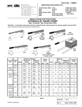
3.0 TECHNICAL SPECIFICATIONS
Model Tool Type Control Usable Oil
Capacity
(cu. in.)
Oil Flow
@ 0 psi (cu. in.)
Oil Flow @
10,000
psi (cu. in.)
Operating Air
Pressure
Range (psi)
Weight
(lbs)
GA90 S/A Foot Pedal 90 68 11 60 - 150 18.5
GA9230 S/A Foot Pedal 230 68 11 60 - 150 32.6
GA9460 S/A Foot Pedal 460 68 11 60 - 150 41
GA90-R S/A Pendant 90 68 8 60 - 150 23.5
GA9230R S/A Pendant 230 68 8 60 - 150 37.6
GA9230D D/A Control Valve 230 68 11 60 - 150 31.6
GA9460D D/A Control Valve 460 68 11 60 - 150 41
DOCUMENTED FLOWS WERE TESTED AT 110 PSI, 10 CFM.
GA9 Series Foot Pumps

www.tksimplex.com
••• 3 •••
4.0 BASIC OPERTION AND FUNCTION
1. Locate and remove the shipping plug and discard. Ensure the oil level is just below (approx. 1/2”) the oil ller plug hole.Install the vent / oil ll /
dip stick plug.
2. Remove air inlet shipping plug and discard. Pour a teaspoon of good quality, air tool #10 wt. non-detergent oil into the air inlet port). Install the
appropriate air supply coupler and a 3/8” NPT hydraulic connection. The air quick disconnect conguration of your choice can be installed in the
threaded hole underneath the foot pedal labeled “PUMP”. An in-line lter/ regulator/lubricator should be installed close to pump. Add a few drops
of SAE 10 oil to the air intake weekly if no lubricator is used or when pump will be idle for a long time.
3. Remove the pressure port shipping plug and discard. Use at least 1-1/2 wraps of Teon tape (or suitable sealant) on the hose tting threads.
Make sure the rst complete thread is free from tape or sealant so they do not enter and contaminate the hydraulic system. Thread the hose t
ting into the pump manifold’s threaded hole and turn until snug - make sure the hose tting threads are not cross-threaded.
4.1 OPERATION
1. Make sure the pump is on a level surface.
2. Connect Foot Pump to an external air source that is capable of supplying 90 PSI @ 10 CFM. Next connect a 3/8” NPT quick disconnect coupler
or hose to the oil outlet side. (SIMPLEX recommends that a gauge adaptor and 10,000 PSI gauge be use during operation). Connect tooling (I.e.
cylinder, bender, or cutter)
3. Check for leaks in system and repair as needed. Before repairs are made, disconnect air source and application, then depressurize reservoir. Do
so simply by pressing the pedal or pendant button for three seconds (see gure 1).
4. To build pressure, depress the pedal or pendant button where “PUMP” is located. Operate pump until desired
position is reached and/orpressure is obtained (see gure 1).
5. To retract application, simply press down on the RELEASE valve or pendant button portion of the pump. Fully
depressing pedal will LOCK the DETENT feature to “on” (see gure 1).
4.2 AFTER COMPLETING THE JOB
Before disconnecting hoses, ttings, etc., be sure the ram is unloaded and retracted, then disconnect air source and hydraulic connections. Store
the pump in a clean, dry area.
5.0 PERIODIC MAINTENANCE
A) MAINTENANCE
1. Inspect hose and connections daily. Replace damaged components immediately with Simplex Authorized replacement parts only.
2. Tighten connections as needed. Use pipe thread Teon when servicing connections. NOTE: DO NOT OVER TIGHTEN CONNECTIONS.
3. When Not In Use Or During Storage:
• Disconnect pump from air source, depressurize and disconnect hydraulic hoses from application.
• Wipe clean, throughout.
• Shelter the pump with protective cover.
• Store in clean, dry environment.
• Avoid temperature extremes.
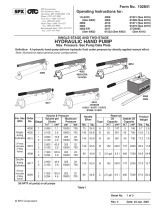
B) HOW TO FILL THE RESERVOIR
1. Disconnect hydraulic hose from application, remove air source from pump.
2. With reservoir horizontal, remove the vent / oil ller plug.
3. Use a small funnel to ll reservoir so the oil level remains the distance stated below in the table, distances are measures from the top of the ll
hole.
Models Recommended Oil Level Range from the Top of Fill Hole
Minimum distance Maximum distance
GA90, GA90R 1.25” .50”
GA9230, GA9230D, GA9230D 3.5” 1.5”
GA9460, GA9460D 1.75” 1.5”
continued on next page.
Figure 1
OIL
AIR SPACE
MINIMUM
FILL LEVEL
MAXIMUM
FILL LEVEL
MEASURE FROM TOP OF
FILL HOLE
CUTAWAY

••• 4 •••
4. Use Simplex oil only (Model # AO1, 1 gallon). Using oil other than Simplex Brand voids the pump warranty.
5. Wipe up any spilled uid and install oil ller screw.
6. Return pump to original position (parallel to a at level surface), reconnect application and air source. Operate for a few seconds, and then
check for leaks.
C) CHANGING THE OIL
1. For best results, change uid once a year.
2. Repeat steps (B) “How to Fill Reservoir”, and then pour used uid into a sealable container.
3. Fill with Simplex oil. Reinstall oil ller plug.
D) LUBRICATION (When no In-Line Oiler is used)
1. When used daily, pour a teaspoon of good quality air tool oil #10 non-detergent oil into the air source inlet of pump. Connect
hydraulic hose to application, connect air source to pump and operate pump a few seconds to evenly distribute uid.
2. Use light machine oil to lubricate pivot points, hinges etc.
NOTE: NEVER OPERATE PUMP WHILE DISCONNECTED FROM APPLICATION. IF OPERATED IN THIS CONDITION, THE HOSE AND
CONNECTIONS BECOME PRESSURIZED. THIS INCREASES THE BURST HAZARD AND DAMAGE MAY OCCUR TO PUMP /
COMPONENTS.
5.1 MAINTAIN OIL LEVEL
Check hydraulic oil level every 30 hours of operation (sight gauge should be completely covered in oil when all tools are retracted. Add Simplex oil
(Model # AO1 – 1 gallon) when necessary. Oil level should be no more than 1/2” from top of reservoir plate – with cylinders retracted and motor off.
6.0 TROUBLESHOOTING
UNIT OPERATES, BUT TOOLING DOES NOT MOVE: NO HYDRAULIC FLOW / LOW FLOW
Reservoir not vented, causing a vacuum Unclog plastic vent plug.
No oil, reservoir empty or low. Check oil level once the tooling is fully retracted, should be ½”
from top of oil tank cover or check that your tooling requirement
does not exceed the foot pump oil capacity.
Defective coupler, not allowing ow. Coupler is not fully seated or ball seats are defective, replace
coupler.
Oil entrance valve clogged. Oil inlet is clogged with foreign matter or seat is defective.
UNIT DOES NOT OPERATE AND AIR BY PASSES: AIR CYLINDER DRY OR DAMAGED AIR VALVE
Insufcient air supply. Ensure you have 110 PSI @ 10 CFM supplied.
Air supply does not have ample lubrication. Use a recommend lubrication such as “Kilfrost”. Apply 1 drop per
minute into foot pump.
Air entrance base has defective seals or is damaged. O-rings are damaged; replace seal or damaged components.
Air piston is frozen, worn seals or air valve is
defective.
Replace O-ring and/or air piston assembly or lubricate
Mufer are completely clogged, not allowing air to pass. Remove and clean or replace mufers. Adjust the external relief
by turning inward.
UNITED STATES HOME
OFFICE AND FACTORY
2525 Gardner Road
Broadview, IL 60155-3719
Phone: (708) 865-1500
Fax: (708) 865-0894
Toll Free: (800) 323-9114
Email: [email protected]
www.tksimplex.com
CANADIAN
EUROPEAN
ASIA & PACIFIC RIM
asiapaci[email protected]
MEXICO
SOUTH & CENTRAL AMERICA
MIDDLE EAST
SOUTH AFRICA
Simplex products are warranted to be free of defects in materials and workmanship under normal use for as long as the original purchaser owns
them, subject to the guidelines and limitations listed. This warranty does not cover : normal wear and tear, cosmetic items, abuse, overloading,
alterations. Improper uid, or use in a manner for which they are not intended. If the customer believes a product is defective, the product must be
delivered, or shipped freight prepaid, to the nearest simplex authorized service center for evaluation and repair.
/